 Documentation
WB-MAI6
6-channel universal analog input module
Covered order codes (1)
WB-MAI6
This page describes the latest hardware revision with the latest stable firmware. If your device runs older firmware, update it where possible (see Firmware update).
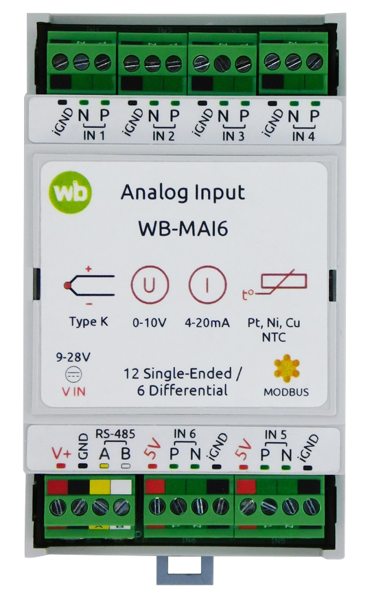
Purpose
The WB-MAI6 analog input module measures resistance temperature sensors, converts standardized current and voltage sensor signals, measures voltage and performs related measurements.
Each input mode is selected in software during configuration. No external burden or pull-up resistors are required. Up to 12 different sensors can be connected simultaneously.
Control the module from a controller or PC over RS-485 using Modbus.
Registered as a measuring instrument under State Register number 94860-25. WB-MAI6 metrological and technical specifications are given in type description.
Supported sensors and signals
| Parameter | Value |
|---|---|
| Thermocouples | |
| Types |
|
| Resistance temperature detectors (RTDs) | |
| Wiring diagrams | Two-wire, three-wire |
| RTD types |
|
| Thermistors | |
| Types |
|
| Sensors with standardized signals | |
| Current | 4–20 mA, 0–20 mA, 0–5 mA |
| Voltage | 0–1 V, 0–10 V (source resistance up to 400 Ω), −50…+50 mV, −2…2 V |
| Other sensors | |
| Current | Hall-effect sensors with 2.5 V ±0.625 V output (HSTS016L) |
| Digital | Dry contact |
| Measured quantities | |
| Voltage | −2 V to 30 V
0 V to 60 V or −30 V to 30 V using WB-VDIV |
| Resistance | up to 2 MΩ |
| Current | up to 20 mA |
For measurement errors, see table 2.
Differences from other Wiren Board analog modules.
Technical specifications
| Parameter | Value |
|---|---|
| Power supply | |
| Supply voltage | 9–28 VDC |
| Power consumption | 0.2 W |
| Maximum 5V output current | 150 mA |
| Measurement channels | |
| Number of channels | 6 differential or 12 single-ended |
| Supported sensors and signals | RTDs, NTC thermistors, K-type thermocouples, current/voltage sensors with standard outputs, Hall-effect sensors, dry-contact sensors, and custom voltage, current and resistance measurements.
For the complete model list, see table 1 |
| Measurement error for standard sensors |
Common RTDs:
K-type thermocouple: ±(0.8 °C + 0.2% × Δt), where Δt is the difference between the measured temperature and the WB-MAI6 temperature. This accuracy is specified for vertical DIN-rail mounting, 15 minutes after power-on, with current measurement disabled on the other channels. In other operating modes, heat redistribution inside the device can increase the error; that error is not specified. Sensors with standardized outputs:
Hall-effect current sensor: ±1%. For errors for all supported standard sensors, see table 4 The stated errors apply to the WB-MAI6 measurement itself and do not include the connected sensors' own errors. |
| Basic voltage measurement error | ±0.2% (< 2 V)
±1.0% (< 30 V) ±(0.2% + 20 mV) (using WB-VDIV) |
| Basic current measurement error | ±0.2 % |
| Basic resistance measurement error | ±0.1% (0…1 kΩ)
±0.2% (1…100 kΩ) |
| Input resistance in voltage measurement mode | > 1 MΩ (0…2 V)
4 kΩ (> 2 V) > 150 kΩ when using WB-VDIV |
| Protection | |
| Simultaneously on all channels, in any mode | ±30 V |
| Terminal blocks and wire cross-sections | |
| Recommended wire cross-section with insulated wire-end ferrules | 0.35–1 mm2 — single ferrule; 0.35–0.5 mm2 — twin ferrule |
| Standard ferrule sleeve length | 8 mm |
| Screw tightening torque | 0.2 N·m |
| Control | |
| Control interface | RS-485 |
| Interface isolation | Galvanically isolated from the measurement circuits |
| Communication protocol | Modbus RTU; software-configurable address; factory settings are printed on the label |
| RS-485 interface parameters | Software-configurable; defaults:
baud rate — 9600 bit/s; data — 8 bits; parity — none (N); stop bits — 2 |
| Ready after power-on | ~3 c |
| Operating conditions | |
| Ambient air temperature | −40 to +80 °C |
| Relative humidity | Up to 98%, non-condensing |
| Warranty | 2 years |
| Service life | 8 years |
| Dimensions | |
| Width, DIN modules | 3 |
| Overall dimensions (L × W × H) | 53 × 90 × 58 mm |
| Weight (including box) | 110 g |
Operating principle
WB-MAI6 has six universal inputs, each connected to the ADC in turn to measure its signals.
The ADC has 16-bit resolution. Each channel has a first-order low-pass filter against high-frequency interference. To improve accuracy for slowly changing signals, oversampling up to 50 and an additional first-order digital low-pass filter are supported. Configure these through the controller web interface Wiren Board or Modbus registers.
The ADC operates differentially, for example for thermocouples and three-wire RTDs, or in single-ended mode, for example for 4–20 mA or 0–1 V signals.
4–20 mA, 0–20 mA and 0–5 mA signals are measured using internal 100 Ω shunts. Two- and three-wire RTD measurements use internal precision 50–1000 µA current sources.
The device includes switchable voltage dividers for higher voltages such as 0–10 V or 30 V. These switch automatically according to the input signal.
The 5V outputs and signal grounds of all six channels are internally connected. The 5V output can power external sensors, such as Hall-effect current sensors.
RS-485 and the power input are galvanically isolated from the measurement channels. Channels are not isolated from each other.
To detect a disconnected K-type thermocouple correctly, input filter capacitors are discharged with microsecond pulses through internal 100 Ω resistors. Consider this when connecting another voltage source instead of a thermocouple. Discharge occurs only in Standard sensors mode with a supported thermocouple selected, not in basic measurement modes.
Two-wire resistance measurement includes lead, joint, contact and terminal resistance. Where possible, use the more accurate three-wire arrangement for low-resistance sensors. Resistance is measured from voltage at a fixed current of 250 µA.
For three-wire measurements, use identical leads to INxP and INxN. With equal leads, the absolute contribution of lead resistance is 0.003Rw, compared with 2Rw for two-wire measurement, where Rw is one lead's resistance. A mismatch contributes an absolute error of |Rw1−Rw2|.
Indicators
The module has an indicator that shows its status without connecting to a controller:
- S (green) — Modbus communication status: lights up when low-voltage power is applied and flashes during polling over RS-485. On devices with events enabled in Fast Modbus ⚡ the indicator flashes more frequently than during ordinary sequential polling because event polling is faster. In bootloader mode it flashes every second; during firmware loading it flashes rapidly. It is below the V+ terminal block.
Installation
Wiring
WB-MAI6 mounts on a standard 35 mm DIN rail and occupies three DIN modules.
The V+ GND A B terminal block, with a 3.5 mm pitch, connects the power supply and RS-485 communication bus. Correct bus wiring is essential for reliable communication; see RS-485 bus wiring and connection.
If devices on the RS-485 bus use different power supplies, their GND terminals must be interconnected. See Grounding Wiren Board devices and connecting GND and iGND.
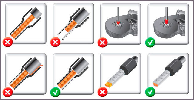
Use flexible stranded wire with insulated wire-end ferrules (NSHVI).
Strip the insulation to the sleeve length, or strip a little more and trim the protruding wire after crimping. Use a ferrule crimping tool. A crimped ferrule protects the strands from the screw clamp and secures the connection.
Do not overtighten the terminal screws: excessive force damages the screw terminal.
Wiring diagrams
The two terminals of an input can be used independently for different signals, for example 4–20 mA on INxP and 0–10 V on INxN.
However, three-wire resistance, differential voltage and thermocouple modes use both INxP and INxN.
- Use one input terminal only: INxP or INxN
-
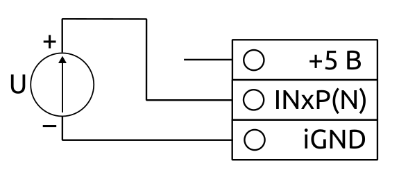 Figure 1. Single-ended voltage measurement: standard 0–1 V/0–10 V sensors, 0–30 V signals, or a Hall-effect current sensor
-
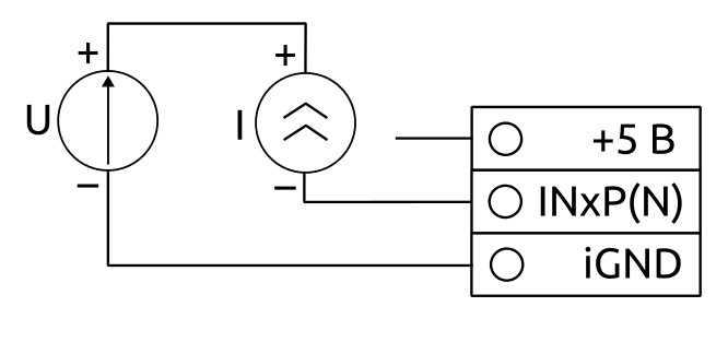 Figure 2. DC current measurement: standard 4–20 mA, 0–20 mA and 0–5 mA sensors, or nonstandard signals up to 20 mA. An external supply is required; connect its ground to the measurement-channel GND
-
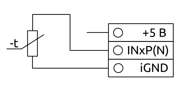 Figure 3. Two-wire resistance measurement: RTDs such as Pt100/Pt1000 and NTC 10k or other thermistors. Use identical leads with ferrules. Lead and contact resistance are included in the reading
-
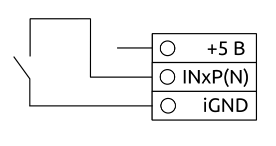 Figure 4. Dry-contact sensor connection
-
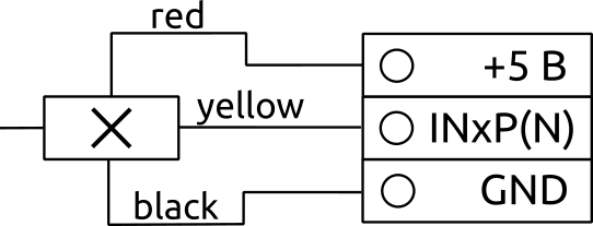 Figure 5. Hall-effect sensor connection
- Use both terminals of one input: INxP and INxN
-
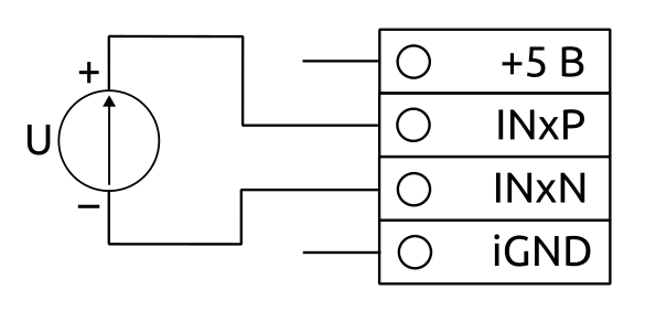 Figure 6. Differential voltage measurement: standard −50…50 mV and −2…2 V signals
-
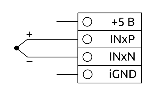 Figure 7. K-type (TXA) thermocouple connection
-
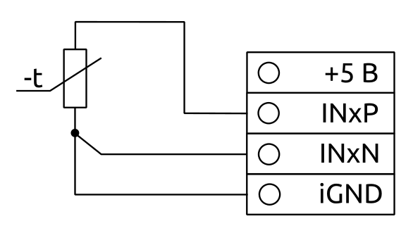 Figure 8. Three-wire resistance measurement. Use identical leads with ferrules. Correct connection compensates lead resistance
When using WB-VDIV for higher voltages or higher input impedance, note that P and N remain electrically independent, but WB-VDIV physically occupies both terminals. Therefore both can be used:
- for positive voltage measurement, with identical settings or the unused channel disabled;
Available from firmware 2.4.0
- for differential P-to-N voltage measurement, accounting for the divider.
Connecting 4–20 (0–20) mA sensors
Passive and active sensors with standardized 4–20 mA or 0–20 mA outputs can be connected.
Module inputs are passive and provide no sensor supply. Use an external supply for passive sensors.
Active three-wire sensors use an external supply whose ground must connect to measurement-channel iGND.
-
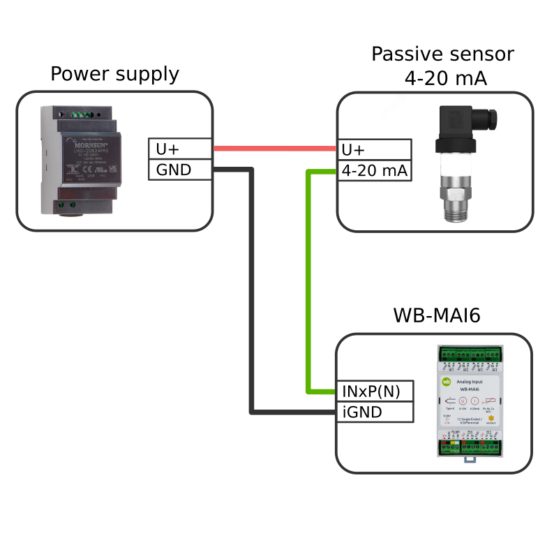 Passive 4–20 mA / 0–20 mA sensor connection
-
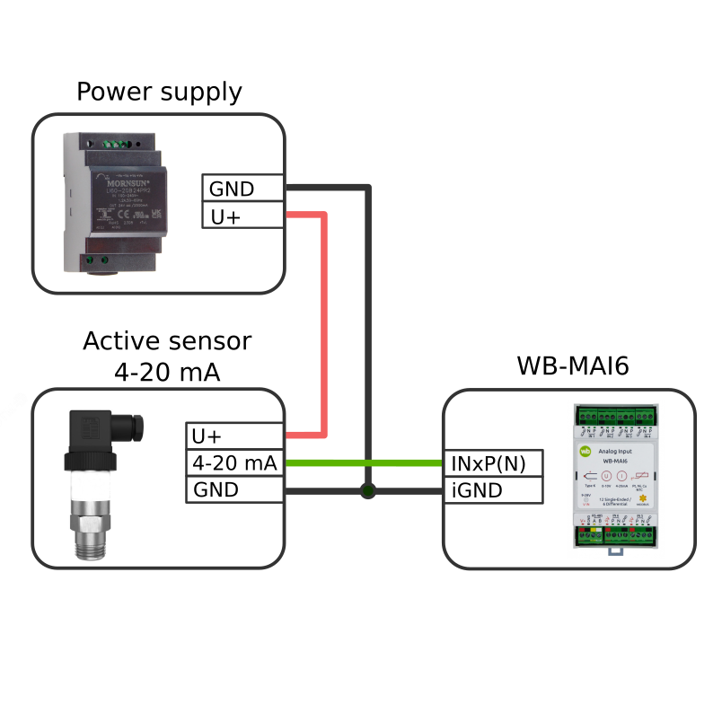 Active 4–20 mA / 0–20 mA sensor connection
Wiren Board controller web interface
Selecting a template
To display the device on the Devices tab of the Wiren Board controller web interface, add it automatically by scanning for Wiren Board devices on RS-485 or manually by selecting the template WB-MAI6.
Controlling the device and viewing values
The web interface allows you to control device outputs and view readings. To change the displayed channels, edit the device configuration in the wb-mqtt-serial driver settings.
The available controls depend on measurement-channel settings.
Configuration
Configuration methods
- Set the parameters in the Wiren Board controller web interface under Settings → Configs → Serial devices driver configuration. If these items are unavailable, check your access level.
- Write settings to the Modbus registers of the module from the controller console using the utility modbus-utils-rpc or modbus_client.
- Without a Wiren Board controller, use the Wiren Board device web configurator or other software; see Using Wiren Board Modbus devices without a controller. You will need a computer with an interface converter: USB-RS485.
Our devices are continually improved. If settings described in this manual are missing, update the device firmware and controller software.
Selecting a sensor or measurement type
All WB-MAI6 channels are disabled by default. Select the connected sensor type or standard signal for each channel. Sensor types automatically convert measurements to physical quantities; for standard signals such as 4–20 mA or 0–10 V, configure the conversion parameters in the channel settings.
Examples below show Pt100 connection/configuration and 0–30 V measurement.
- Configuring a three-wire Pt100
-
Connection diagram, figure 8
-
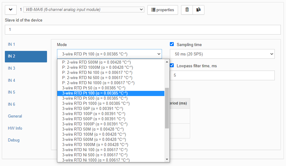 Selecting the sensor
-
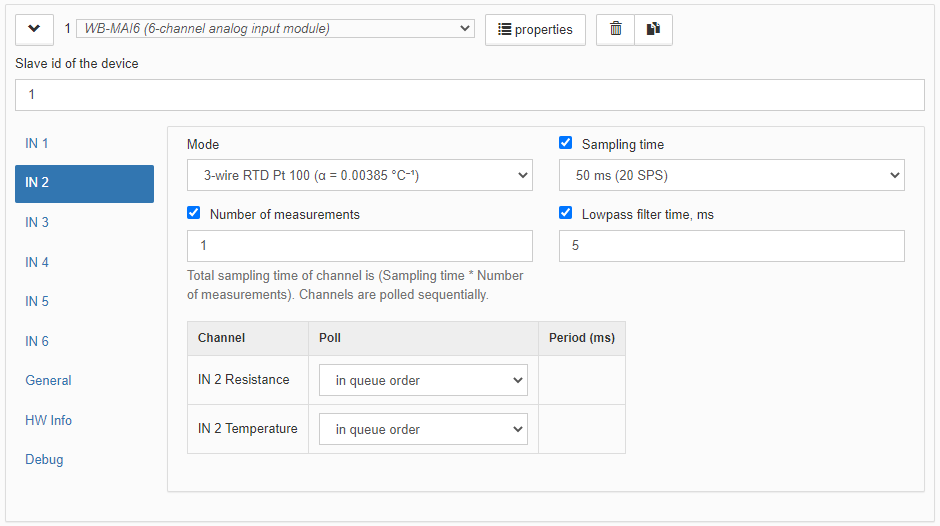 Sensor parameters
-
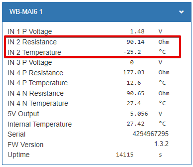 Sensor readings
- Measuring voltage from 0 to 30 V
-
Connection diagram, figure 1
-
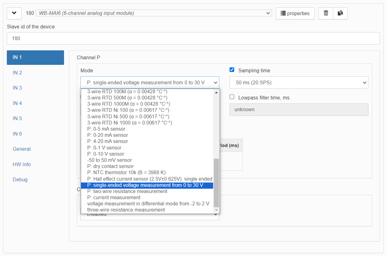 Selecting the mode
-
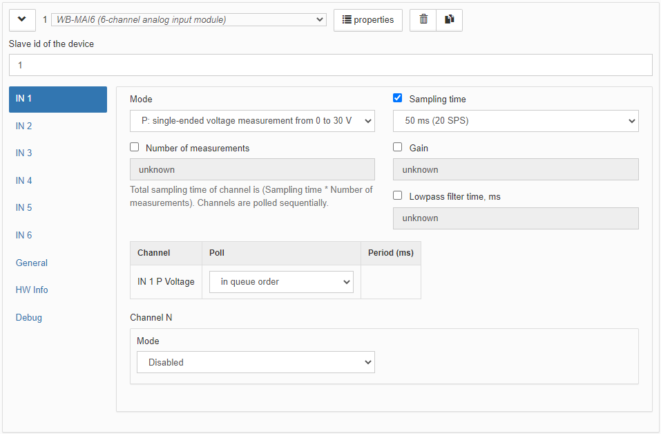 Parameters
-
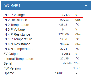 Voltage at terminal P of channel 1
Connecting two sensors to one channel
Depending on the wiring, up to two sensors can connect to one channel. Corresponding measurement modes begin with P — specify the sensor connected to terminal P of the selected channel.
After selecting a value in Mode, an additional field appears below: Channel N. Specify the sensor connected to terminal N or disable polling of that terminal by selecting Disabled.
In the example below, channel 4 has two sensors:
- Terminal P — dry-contact sensor.
- Terminal N — resistive-output sensor.
- Connecting two sensors to one channel
-
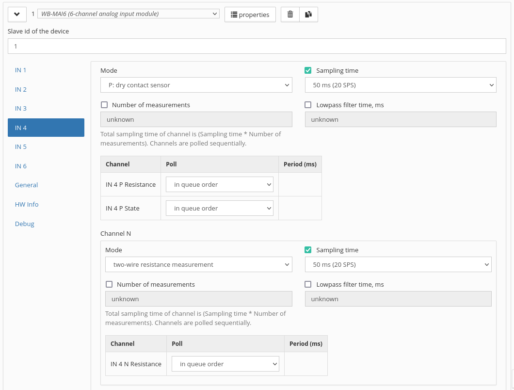 A dry-contact sensor on P and a resistive-output sensor on N
-
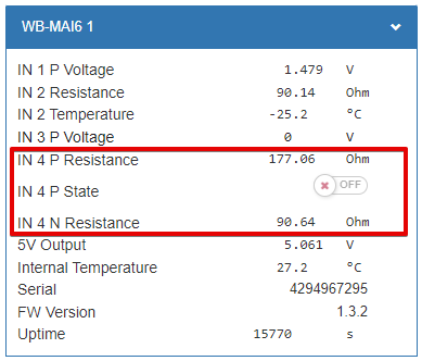 IN 4 P Resistance and State — dry-contact sensor values; IN 4 N Resistance — resistive sensor value
Scaling readings to engineering units
WB-MAI6 software can convert measured values into physical quantities.
Selecting a specific sensor type, such as an RTD or thermocouple, enables automatic conversion. For a standard signal, configure conversion using the channel fields Minimum converted value and Maximum converted value with the physical values corresponding to the signal range minimum and maximum.
The example below configures an SCT-013-015 current sensor with a 0–1 V output and 0–15 A range. Select the appropriate signal range [-32.768; 32.766] and set the lower and upper range limits to 0 and 15 respectively.
Since this sensor connects to terminal P and the selected mode has the prefix P, another sensor can connect to terminal N; configure it in Channel N and choose an available sensor type. In this example, Channel N is unused and therefore disabled.
More about formulas for converting measured values into physical quantities.
- Configuring SCT-013-015: 0–1 V signal, 0–15 A measurement range
-
Connection diagram, figure 1
-
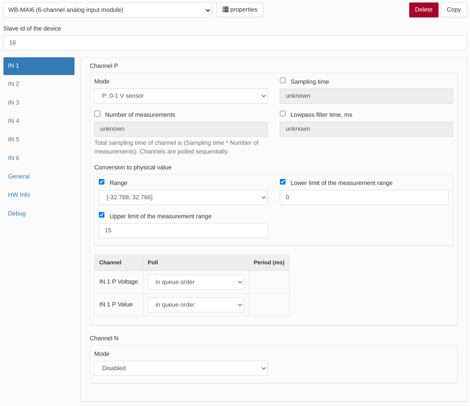 Setting minimum and maximum converted values
-
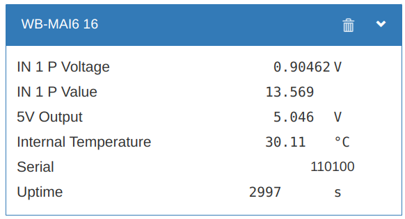 IN 1 P Voltage — measured terminal P voltage,
IN 1 P Value — converted current in amperes
Using K-type thermocouples
A thermocouple measures the temperature difference between its hot junction and cold junction, not absolute temperature. The cold junction is where the chromel and alumel thermocouple wires join copper conductors, normally at the WB-MAI6 input terminals. To obtain the hot-junction temperature, the module adds the calculated cold-junction temperature to the measured difference.
Cold-junction compensation
Terminal temperature is calculated as the WB-MAI6 internal-sensor temperature (register 0x0601) minus the channel-specific correction. The correction compensates for the difference between the warmer circuit board inside the enclosure and the cooler external terminals.
From firmware 2.6.0, corrections are stored in registers 0xX412. Default values are 3 °C for IN1–IN4, 2 °C for IN5 and 1 °C for IN6. Before firmware 2.6.0, the cold-junction temperature was taken as the device's internal temperature, so readings become lower by the correction value after updating.
Default values were determined with vertical DIN-rail mounting, 15 minutes after power-on, at a 24 V supply, with current measurement disabled on adjacent channels. Device orientation, airflow and adjacent-channel modes can change the temperature difference.
Adjusting the correction
For each channel, adjust the correction in the web interface using Cold-junction temperature correction (°C) in the P-channel settings for K-type thermocouple mode, or through Modbus register 0xX412. The adjustment range is −10 to 10 °C.
- Install the device in its operating position and connect the thermocouple to the required input.
- Place the hot junction next to a reference thermometer, at least 0.5 m from the device.
- Run the device in its normal operating configuration, including the required adjacent-channel modes, and wait at least 30 minutes.
- Compare the channel reading with the reference thermometer. If the reading is higher by ΔT, increase the channel correction by ΔT; if lower, decrease it.
Remote cold junction
If operating conditions change continuously or accuracy better than ±1 °C is required, move the cold junction to a location with a stable, known temperature:
- Extend both thermocouple wires with copper wires at least 10 cm long. Make both joints beside each other at one point, away from heat-generating devices.
- Install a reference temperature sensor at the joints, such as a DS18B20 on the controller's 1-Wire bus or a Pt100 on an unused WB-MAI6 channel.
- Set this channel's correction to 0 and recalculate the reading: subtract from the thermocouple reading the difference between the Internal Temperature channel and the reference sensor.
Using Hall-effect current sensors
For installation instructions, consult the sensor documentation HSTS016L.
First, select the mode for the WB-MAI6 input connected to the sensor: Hall-effect current sensor (2.5 V ±0.625 V), single-ended connection and configure:
- Rated current (A) — the nominal current from the sensor documentation.
- Zero offset (A) — enter 0.
- Click Save at the top left of the page.
Next, read the sensor with no conductor through it, or with zero current in the measured circuit, then:
- Open device settings.
- Enter the measured value in Zero offset (A)with its sign reversed.
- Click Save at the top left of the page.
- Configuring a Hall-effect current sensor
-
Connection diagram, figure 5
-
WB-MAI6 channel settings
-
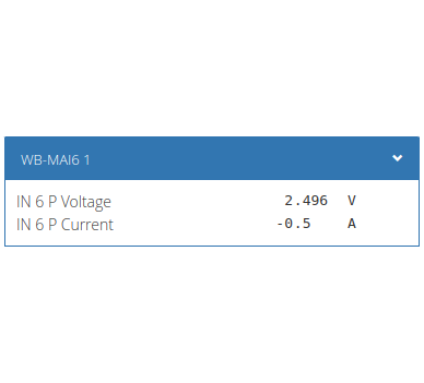 Measuring zero offset
-
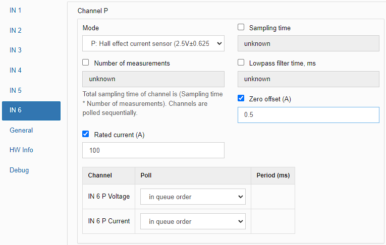 Setting zero offset
Differential voltage measurement
Some measurements involve a floating source, with neither signal lead referenced to ground, for example standard −50…50 mV or −2…+2 V sensors.
Use WB-MAI6 differential mode for these signals.
Differential mode measures the potential difference between N and P. INxP and INxN potentials relative to iGND must remain within 0–5 V; alternatively, the sensor must be floating relative to iGND.
The source connection cable must not exceed 10 m.
Input resistance is slightly above 1 MΩ. For accurate readings, source resistance should be at least two orders of magnitude lower.
If the sensor needs external power, use the module output, up to 150 mA.
- Differential measurement settings
-
Connection diagram, figure 6
-
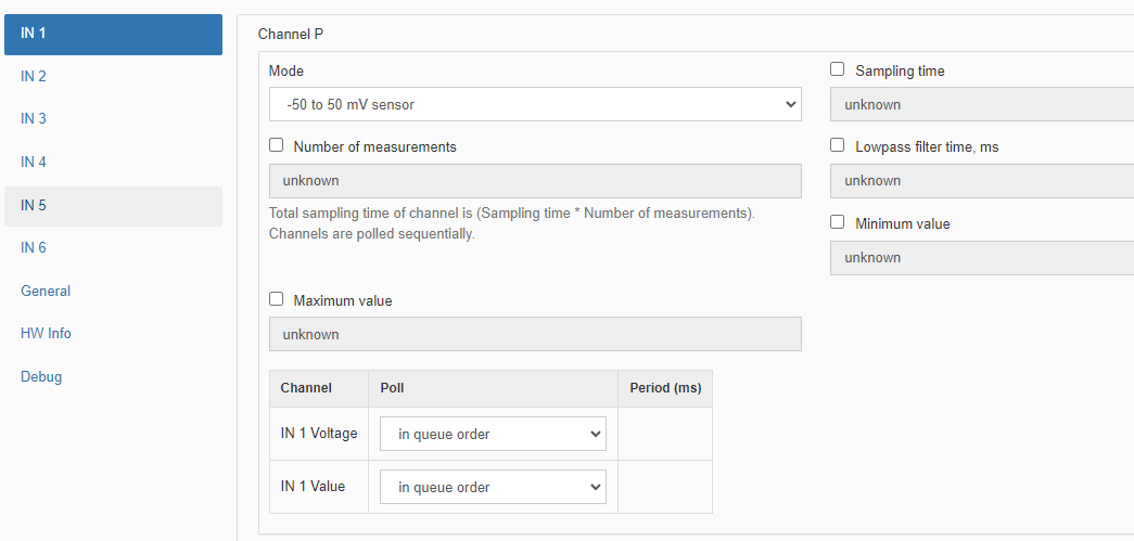 WB-MAI6 channel settings
Differential voltage measurement with WB-VDIV
Available from firmware 2.4.0 WB-MAI6 with the divider WB-VDIV can measure differential P-to-N voltages from −30 V to +30 V. Select Differential voltage measurement with WB-VDIV. This is useful, for example, for individual cells in a battery pack, as shown below. Although measurement is differential, a divider is involved: connect iGND to the source or sources' ground, and keep total source voltage at or below 60 V. Fuses are recommended for battery-cell measurements.
- Differential measurement wiring with WB-VDIV
-
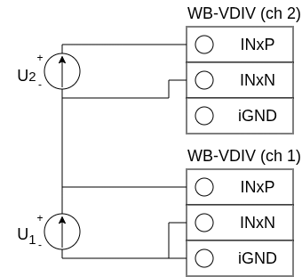 Connection diagram
Voltage measurement with an external divider
For higher voltages, differential voltage measurement from firmware 2.4.0, or higher input resistance above 4.5 V, use an external divider such as WB-VDIV.
A custom two-resistor divider can also be used. WB-MAI6 provides the mode Positive voltage measurement with a custom external divider. Build the divider as shown, select this mode and enter R1 and R2 in kΩ.
Follow these recommendations when choosing divider resistors:
- divider output must not exceed 4.5 V; ideally keep it at or below 2 V for better accuracy. At approximately 4.6 V, WB-MAI6 enables its internal divider, resulting in incorrect readings;
- do not make the lower resistor R2 substantially greater than 10 kΩ. Despite the high input impedance, internal channel switching may affect accuracy with large R2 values;
- consider resistor tolerance, operating conditions and temperature coefficient when accuracy matters;
- for high voltages, also select R1 for its voltage and power-dissipation ratings;
- the mode accepts resistance settings from 0.1 kΩ to 1 MΩ. Larger resistors can be represented by values within that range giving the same ratio. For a 10 MΩ / 10 kΩ divider, ratio 1001, enter 1000 kΩ and 1 kΩ to obtain correct readings.
- Using an external voltage divider
-
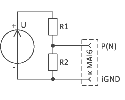 Connection diagram
-
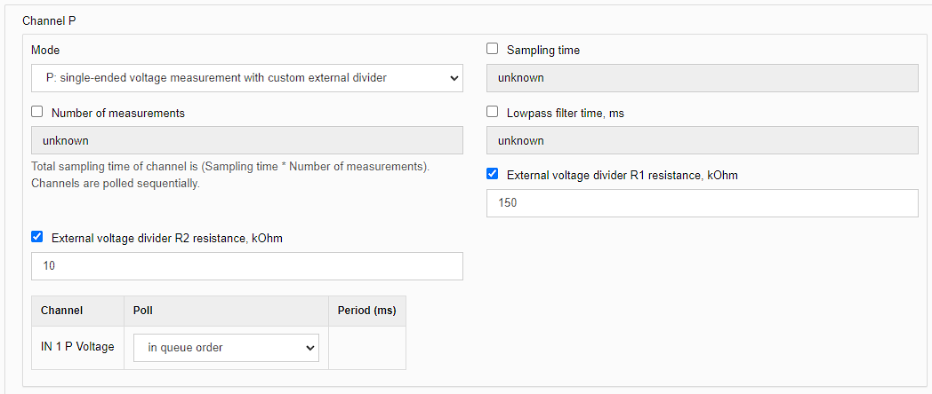 WB-MAI6 channel configuration for a custom divider
-
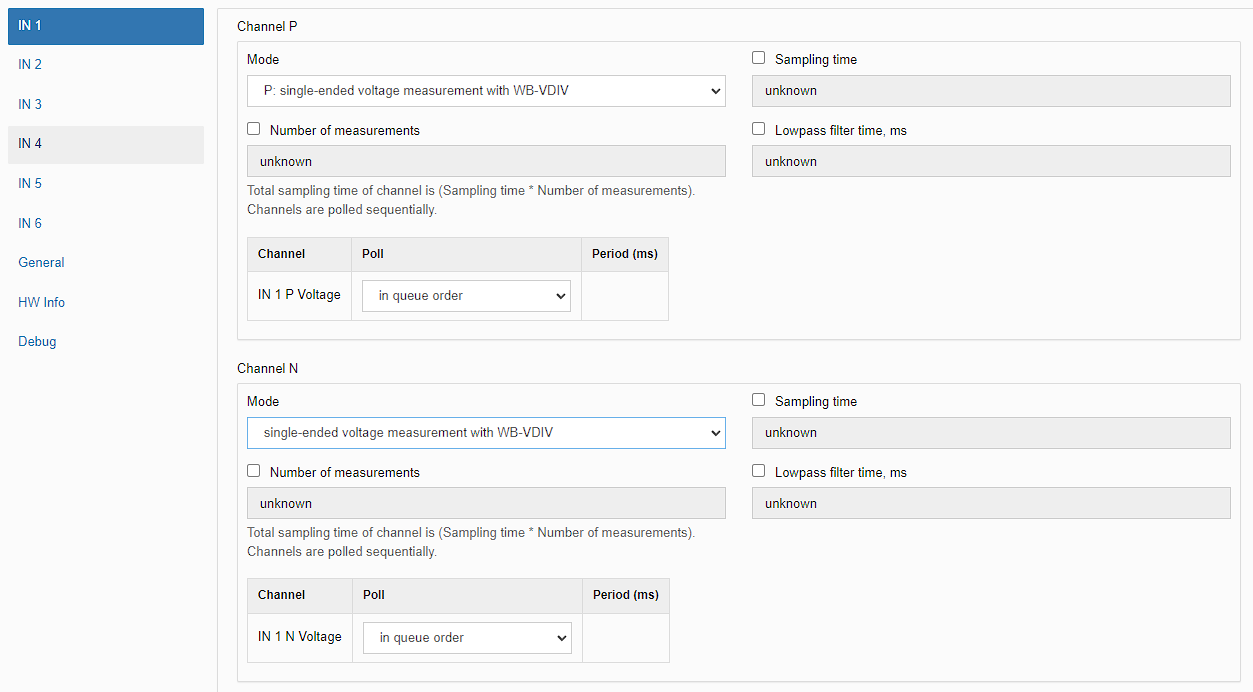 WB-MAI6 channel configuration for WB-VDIV
Modbus operation
Wiren Board devices use Modbus RTU. The physical connection uses the RS-485.
interface. All main commands for reading and writing one or multiple registers are supported. See the list in the Modbus protocol description.
The module can be configured:
- in the Wiren Board controller web interface;
- using the Wiren Board device web configurator;
- using third-party software.
Default port settings
| Value default |
Parameter name in the web interface |
Parameter |
|---|---|---|
| 9600 | Baud rate | Baud rate, bit/s |
| 8 | Data bits | Number of data bits |
| None | Parity | Parity |
| 2 | Stop bits | Number of stop bits |
In current firmware, setting Stop bits is optional: the device also operates correctly when its number of stop bits differs from the Modbus master setting.
For a faster response, we recommend increasing the baud rate to 115200 bit/s; see Communication parameter settings
Modbus address
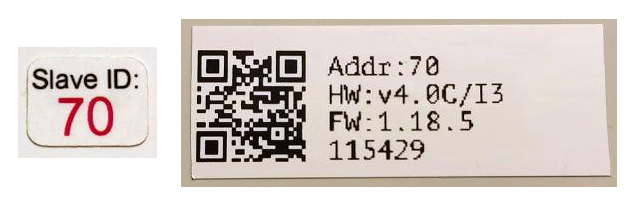
Each device on the bus must have a unique address from 1 to 247. The factory-assigned address is printed on labels on the enclosure (top cover, side or underside). Devices in a production batch are assigned different addresses, so devices in one order will usually have different addresses.
For instructions on finding, changing or resetting the address, see Wiren Board device Modbus address.
Fast Modbus extension
Fast Modbus extends standard Modbus with rapid discovery of Wiren Board devices on RS-485 and event polling.
These features are enabled by a special command from the master, so Wiren Board devices remain compatible with third-party equipment.
Not every register supports event generation. Check the register map: event-capable registers are marked with ⚡. See Fast Modbus.
Register map
Modbus registers, operating modes and standard sensor types
Firmware updates and resetting settings
Wiren Board devices support firmware updates over Modbus. This allows bugs to be fixed at the installation site and, where technically possible, new features to be added. Settings stored in the device are retained during a firmware update.
Instructions:
- Firmware update ()
- Resetting settings
- Connection parameter settings
- Modbus address: find, reset or change
- Updating the bootloader
New firmware releases are listed in the firmware changelog.
Known issues
Hardware revisions
Device images and drawings
CorelDRAW 2018 (font: Ubuntu): File: WB-Library.cdr.zip
Visio:
- Wiren Board devices: File: WB-Visio-Lib.zip.
- Enclosures, circuit breakers, contactors and other third-party symbols.

Module dimensional drawing (DXF): File: WB-MAI6.dxf.zip
Module dimensional drawing (PDF): File: WB-MAI6.dxf.pdf
3D STEP model: File: WB-MAI6.step.zip
AutoCAD Electrical schematic symbol library: File: Wirenboard-AE-base.zip
-
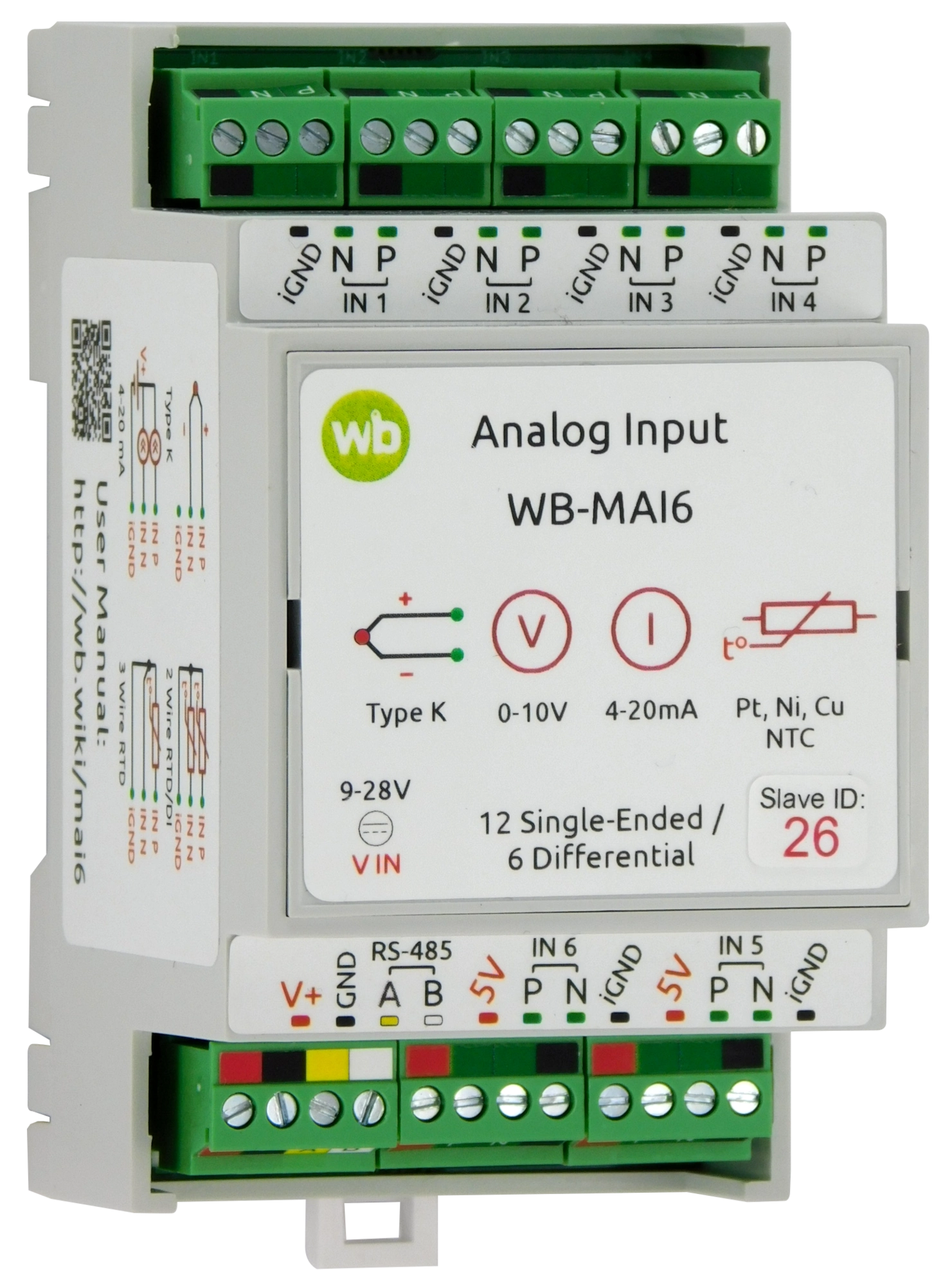 WB-MAI6
-
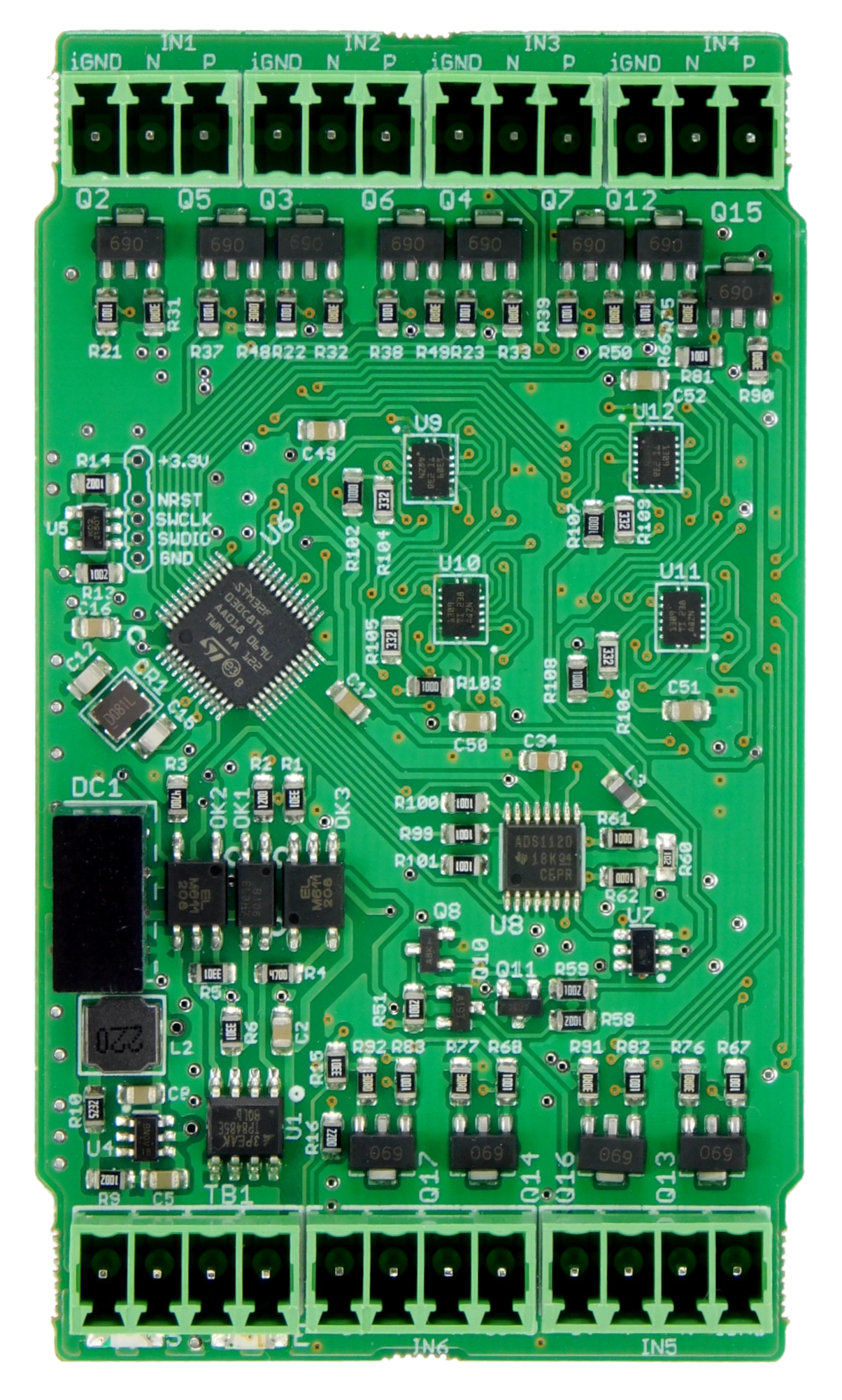 WB-MAI6 PCB
-
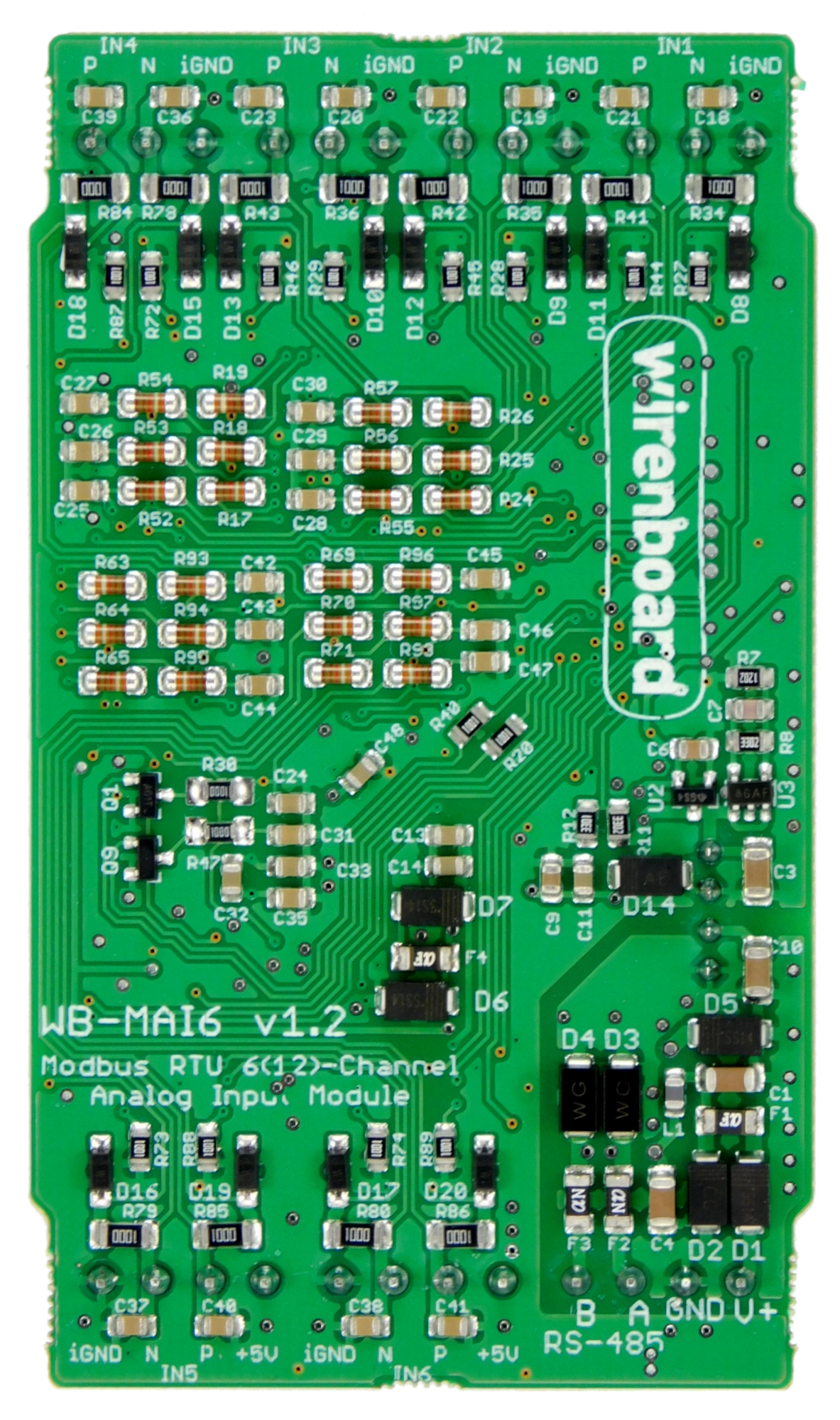 WB-MAI6 PCB
-
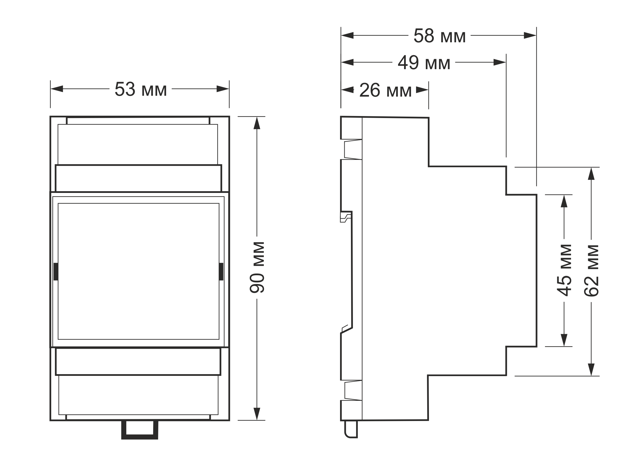 Overall dimensions