 Documentation
WB-VDIV voltage divider
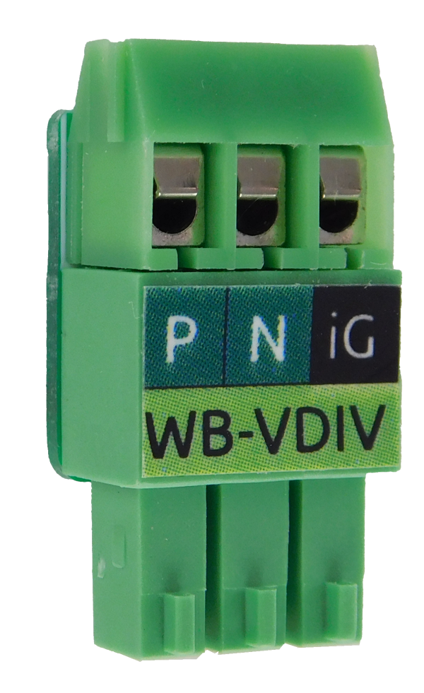
Description
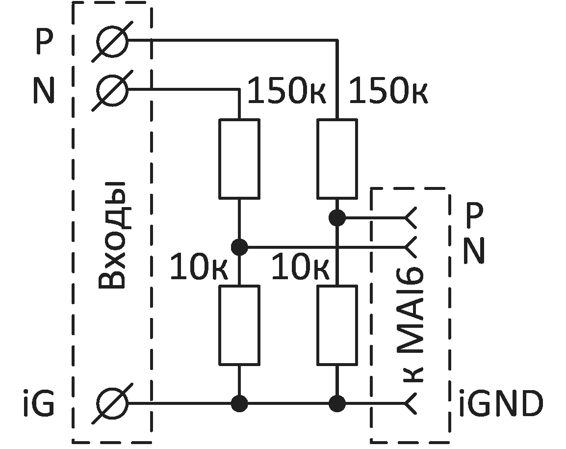
WB-VDIV is a voltage divider for WB-MAI6. It supports voltage measurement up to 60 V and increases WB-MAI6 input impedance when measuring above 4.5 V.
The board contains two resistive dividers for WB-MAI6 P and N channels, a screw terminal block for the signal source, and a mating connector for WB-MAI6.
Together with WB-MAI6, it provides voltage measurement accuracy of approximately 0.2% (details).
WB-VDIV brings the measured voltage into 0–2 V, where WB-MAI6 has its highest accuracy and input impedance, or 0–4.5 V, where accuracy remains close to maximum.
It can therefore increase WB-MAI6 input impedance, for example for 0–10 V signals, and extend its voltage measurement range.
WB-VDIV replaces the standard WB-MAI6 screw terminal block. Its low height permits fitting the enclosure cover panel.
Technical specifications
| Parameter | Value |
|---|---|
| Voltage division ratio | 16 |
| Input impedance | > 150 kΩ |
| Number of channels | 2 |
| Maximum input voltage | 60 V |
| Wire strip length | 4 mm |
| Screw tightening torque | 0.2 N·m |
| Dimensions (D × W × H) | 9 × 11.3 × 23 mm |
| Weight | 3 g |
| Warranty period | 2 years |
| Service life | 8 years |
Wiring
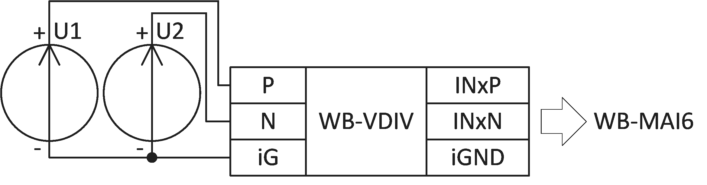
- Check WB-MAI6 firmware: WB-VDIV support was added in 2.1.0
- Insert WB-VDIV into the WB-MAI6 channel connector. Its connector has three positions. On channels 5 and 6 of WB-MAI6, use the rightmost three positions of the four-position connector; terminal 5V remains unused.
- Insert wires into WB-VDIV terminals and tighten the screws.
Configuration
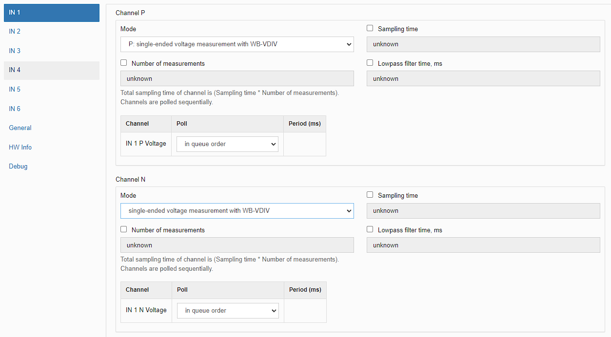
For correct voltage readings, configure WB-MAI6 according to the documentation: set both P and N channels of the corresponding WB-MAI6 input to Positive voltage measurement with WB-VDIV divider.
Hardware revisions
The batch number (Batch No.) is shown on a label on the side of the enclosure or on the printed circuit board.
| Revision | Batches | Production period | Changes from the previous revision |
|---|---|---|---|
| v1.1 | v1.1A, v1.1B, v1.1C - ... | 05.2024 - ... |
|