 Documentation
WBIO-DI-WD-14
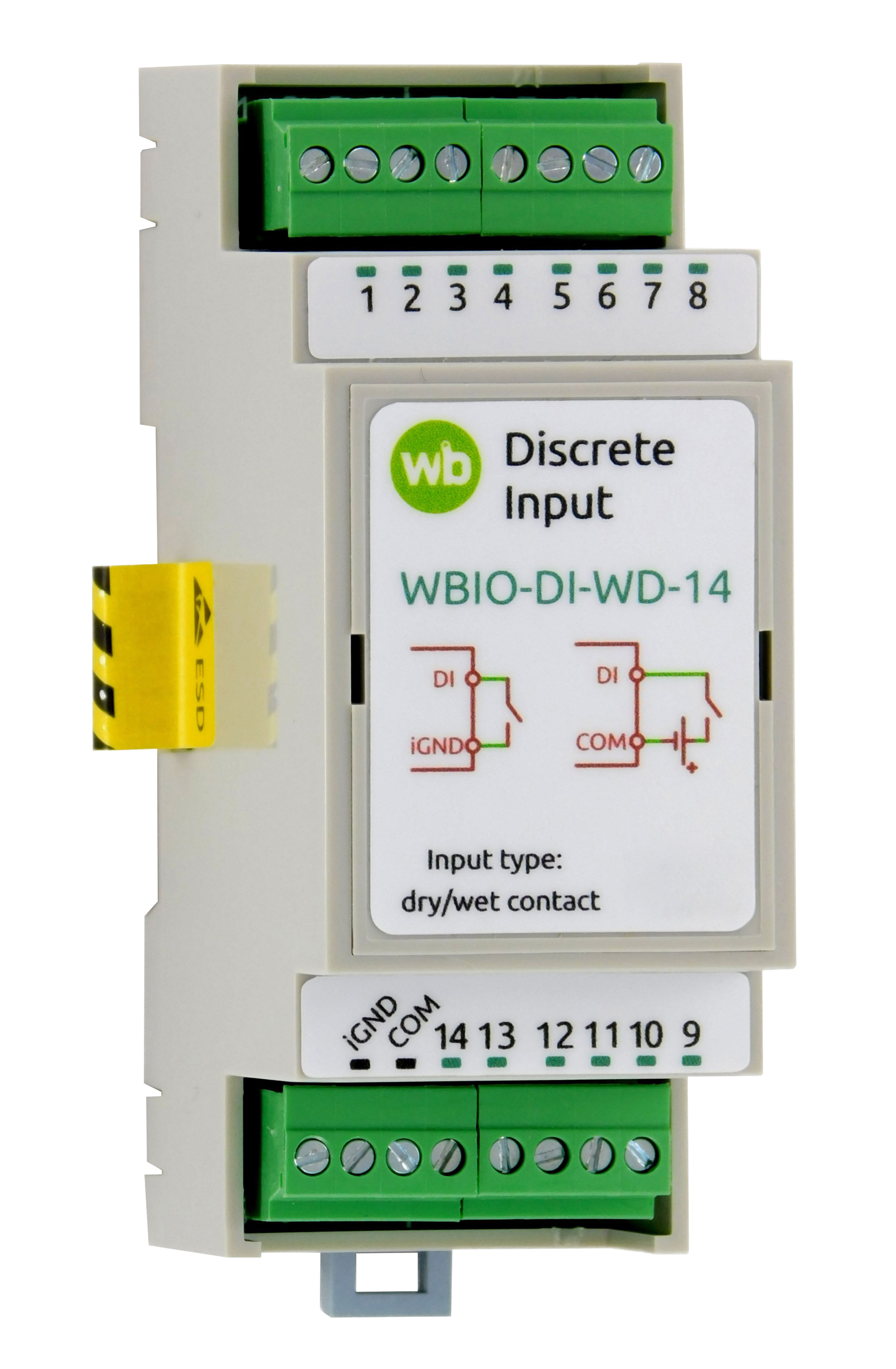
14-channel universal digital input module
Covered order codes (1)
WBIO-DI-WD-14
Purpose
The module connects pulse meters, buttons, switches and sensors with dry-contact outputs. It can also receive digital signals, monitor circuit continuity and perform similar functions. See Digital inputs.
If you plan to connect switches to WBIO-DI-WD-14, we recommend using the WB-MCM8 module instead, which recognizes several press types.
It has no built-in pulse-counting function. Implement counting in software or use the WB-MCM8 module. Example wb-rules rules: Counting pulses on a digital input.
Technical specifications
| Parameter | Value |
|---|---|
| Number of inputs | 14 |
| Isolated input groups | 1 |
| Input type | Dry contact / voltage presence; 1500 V group isolation |
| Minimum detectable pulse width | 25 ms |
| Maximum pulse frequency | 20 Hz |
| Module type | "I" (inverted address scheme) |
| Power consumption | 0.5 W |
| Dry-contact mode | |
| Activation condition | Connect the input to iGND (COM on the older module) or
apply voltage between the input and COM (iGND on the older module) |
| Activation current | 1 mA |
| Wetting voltage | 12 V |
| Voltage-presence mode | |
| Activation voltage
(either polarity) |
|
| Nominal voltage | 12–24 V AC/DC |
| Maximum permissible voltage | 50 V AC/DC |
| Operating conditions | |
| Ambient air temperature | −40 to +80 °C |
| Relative humidity | Up to 95%, non-condensing |
| Climatic classification under GOST 15150-69 | O2.1* |
| Warranty | 2 years |
| Service life | 8 years |
| Compatibility | |
| Compatible controllers | Wiren Board 5, 6, 7, 8 |
| Compatible modules | WB-MIO, WB-MIO-E and WB-MGE v.3 interface modules |
| Terminal blocks and wire cross-sections | |
| Recommended wire cross-section with insulated wire-end ferrules | 0.35–1 mm2 — single ferrule; 0.35–0.5 mm2 — twin ferrule |
| Standard ferrule sleeve length | 8 mm |
| Screw tightening torque | 0.2 N·m |
| Dimensions | |
| Width, DIN modules | 2 |
| Overall dimensions (L × W × H) | 36 × 90 × 58 mm |
| Weight (including box) | 80 g |
Operating principle
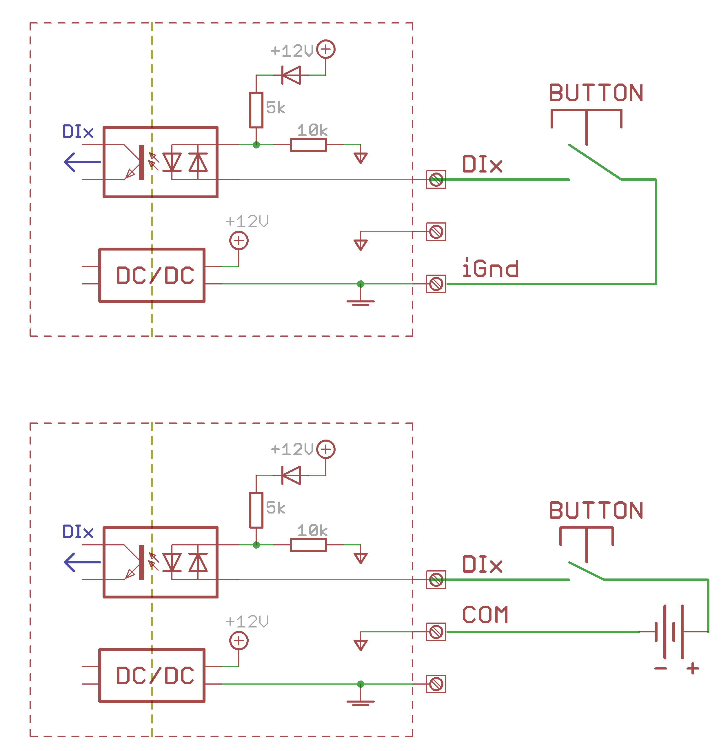
Contains 14 universal inputs for dry contacts and low-voltage detection, with group galvanic isolation. Operating mode depends on the wiring arrangement. The terminals provide approximately 12 V relative to iGND (COM on the older module). Closing an input to this terminal draws a small current (2 mA), activating the input. An input also activates when external voltage of either polarity, or 50 Hz AC, is applied between the input and COM (iGND on the older module). Both modes can be used simultaneously.
Installation
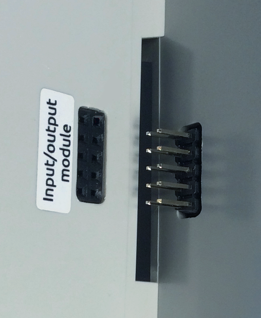
I/O modules attach to the right-hand side of a Wiren Board controller or WB-MIO, WB-MIO-E or WB-MGE v.3 interface converter through the side connector. Ensure every pin enters the mating connector correctly. Secure the assembly with DIN-rail end stops, leaving approximately 2 cm of spare space for quick removal.
Up to eight modules can be connected in sequence: up to four input modules (type I) and up to four output modules (type O). The WBIO-AI-DV-12 is an exception: only one module of this model can be connected.
Addresses are assigned sequentially. Up to four modules can be connected in any order. For more than four modules, connect all modules of one type first, followed by all modules of the other type.
Digital inputs activate when connected to iGND. The current is low (~2 mA), so any suitable button or switch type can be used. Cable length and cross-section are not critical for contact detection. To reduce interference from nearby power wiring, use twisted pair and connect iGND to the second conductor of the pair. More about connecting iGND/GND terminals.
Connecting external devices
WARNING: On the first module versions, manufactured before May 2019, COM and iGND terminals are swapped and their functions differ. Follow the terminal labels and wiring diagram on the module. See wiring diagrams for the first version.
Sensors/meters with pulse outputs and buttons.
These devices signal by closing the circuit between two wires. Connect one wire to the module's iGND terminal (COM on the older version). Connect the other wire to Dx. Some meters use optocoupler pulse outputs with positive and negative polarity. Connect negative to iGND and positive to Dx.
Devices with open-collector outputs.
Connect the device ground to the module's iGND terminal. Connect its open-collector output to Dx.
The module inputs are galvanically isolated from the controller, so the connected device and controller can have different ground potentials.
 |
Configuration in the controller web interface
Configuration with a Wiren Board controller
After physically connecting the module, add it to the controller configuration:
- In the web interface, open Settings → Configs.
- Open Expansion modules and ports and select the WBIO module (External I/O module) slot corresponding to the connected WBIO side module.
- In the Module type list, select the type of module installed.
- Click Save.
WBIO modules do not support hot plugging.
To remove a module from the configuration, select Not installed.
Check that the external module is visible in the web interface:
- Open Devices.
- Find the Discrete I/O for digital modules, or ADCs for analog modules. Channel names follow the pattern EXTN_YYYY, where N is the module sequence number and YYY is the module channel name.
The MQTT topic address follows the pattern /devices/wb-gpio/controls/EXTN_YYYY.
-
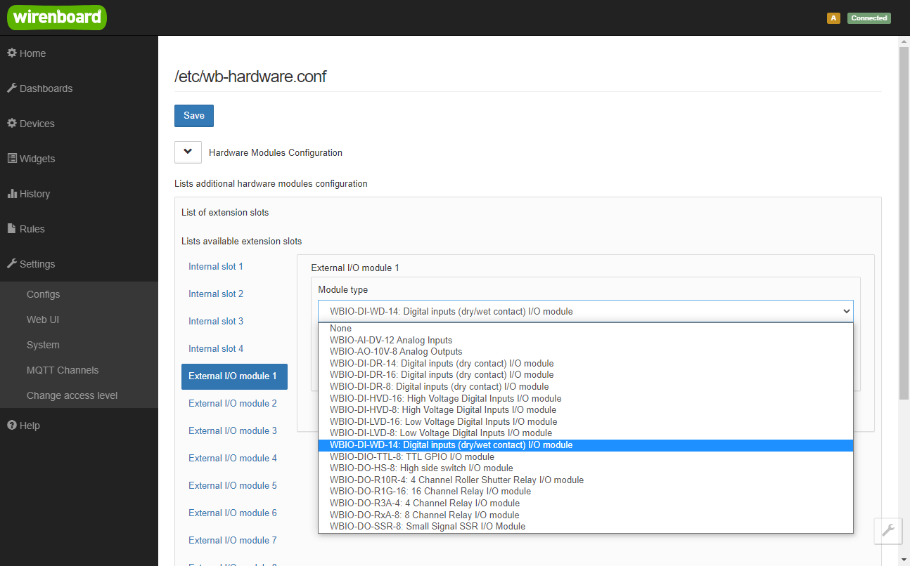 Configuring a new side module
-
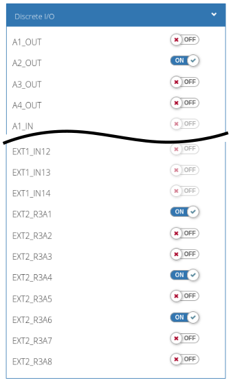 External module channels in the Wiren Board controller web interface
Configuration with WB-MIO
Configuration with WB-MGE v.3
Hardware revisions
The batch number is printed on a label on the side of the enclosure or on the PCB.
| Revision | Batches | Release date | Changes from the previous revision |
|---|---|---|---|
| 2.2 | v2.2A, v2.2B, v2.2B/1, v2.2B/2, v2.2C, v2.2C/1, v2.2C/2, v2.2D, v2.2D/1 - ... | 04.2025 - ... |
|
| 1.3 | v1.3A - v1.3D (/1), v1.3E, v1.3E/2, v1.3F, v1.3F/2, v1.3G, v1.3H, v1.3I, v1.3J, v1.3J/1, v1.3K, v1.3L, v1.3M, v1.3N, v1.3O, v1.3P | 05.2022 - 04.2025 |
|
| 1.1 | v1.1D - v1.1N, v1.1N/2, v1.1O, v1.1P, 1.1Q | 09.2019 - 05.2022 |
|
| 1.1 | v1.1A - v1.1C | 05.2019 - 10.2019 |
|
| 1.0 | 313 | Before May 2019 |
|
Device images and drawings
CorelDRAW 2018 (font: Ubuntu): File: WB-Library.cdr.zip
Visio:
- Wiren Board devices: File: WB-Visio-Lib.zip.
- Enclosures, circuit breakers, contactors and other third-party symbols.

Autocad 2013 DXF: WBIO-DI-WD-14.dxf.zip
Autocad PDF: WBIO-DI-WD-14.pdf
-
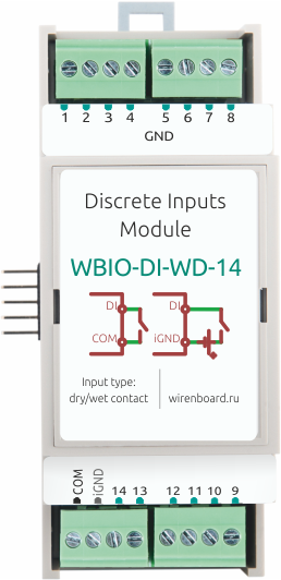 First-release WBIO-DI-WD-14 module
-
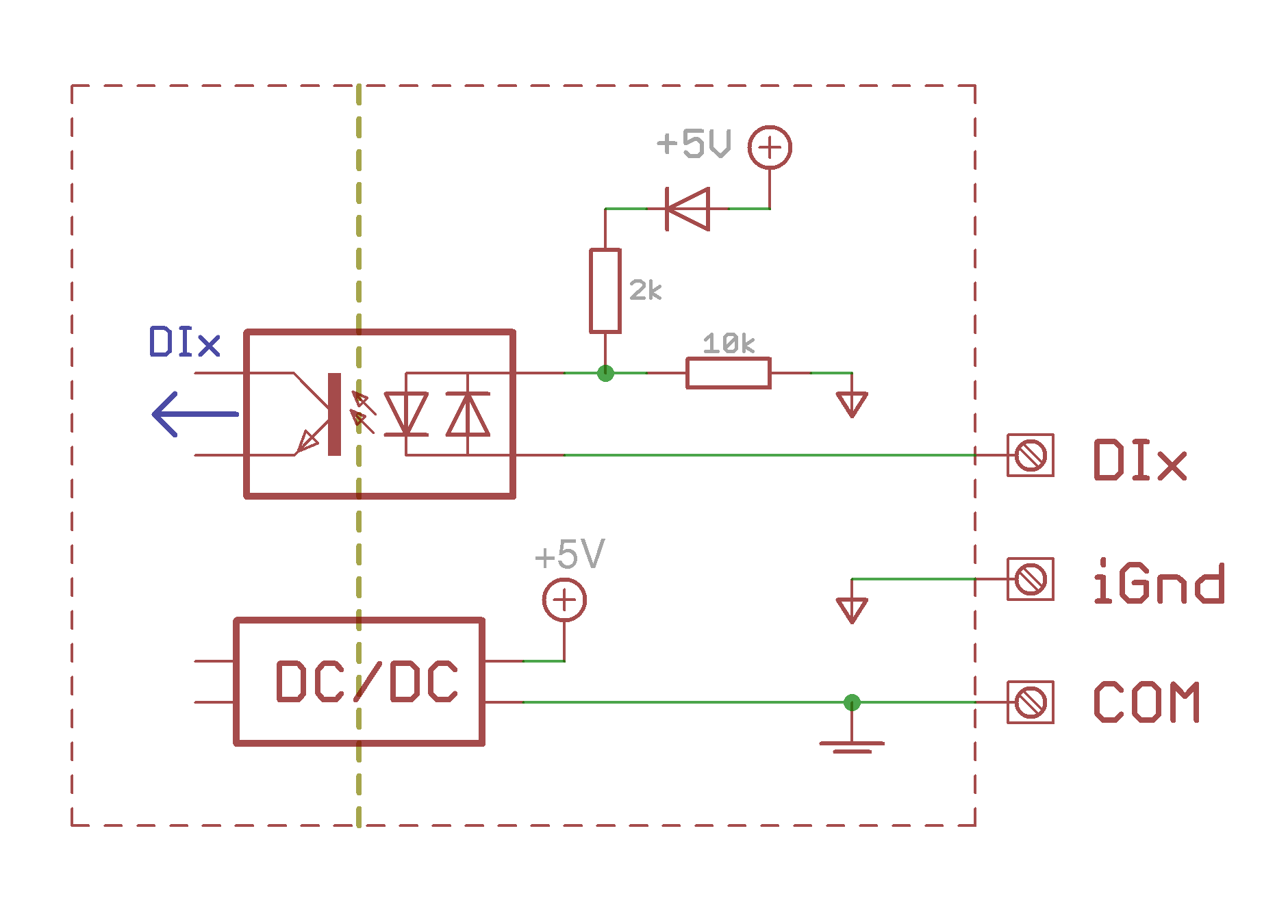 Input circuit of the first-release WBIO-DI-WD-14
-
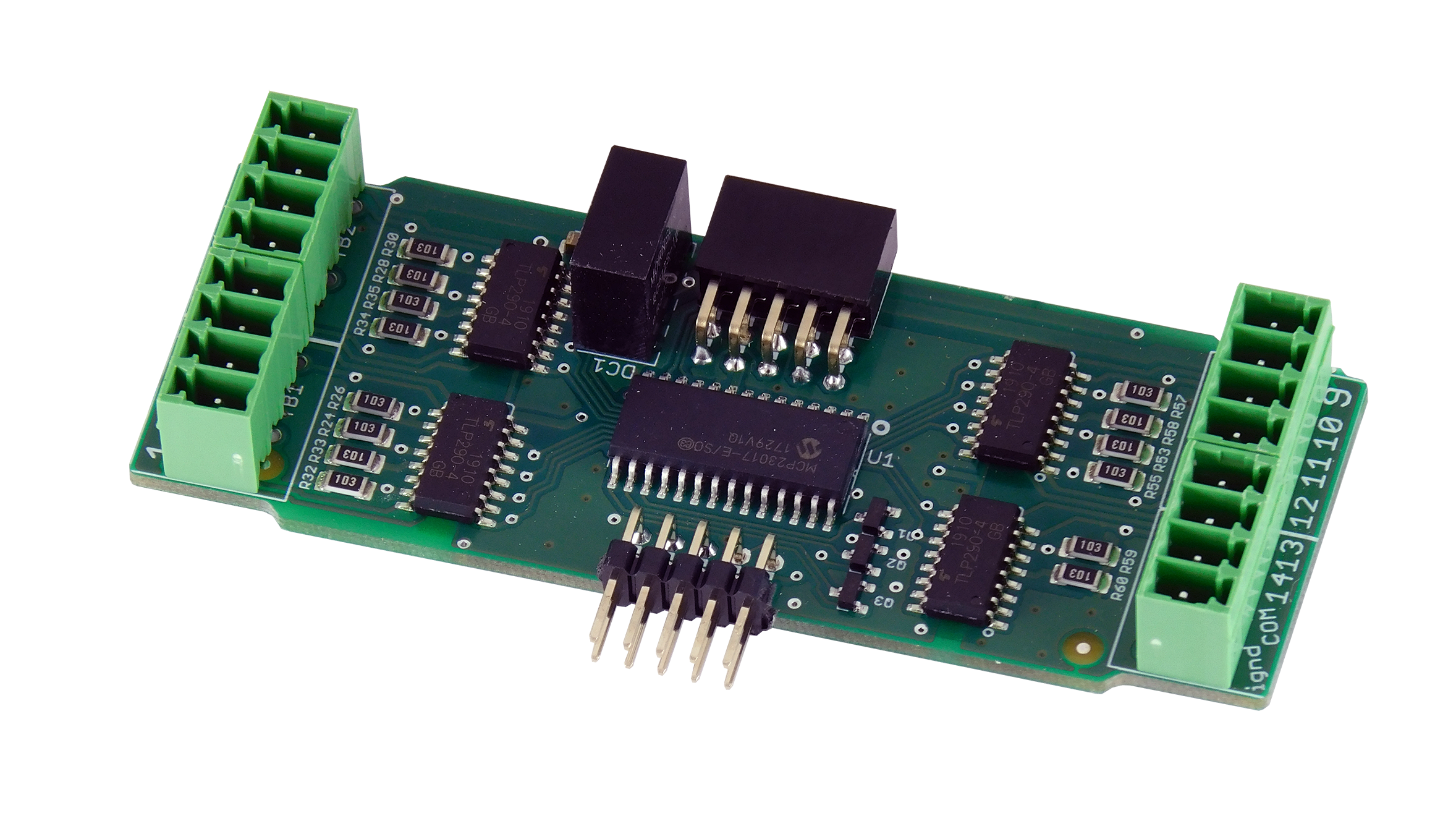 First-release WBIO-DI-WD-14 PCB
-
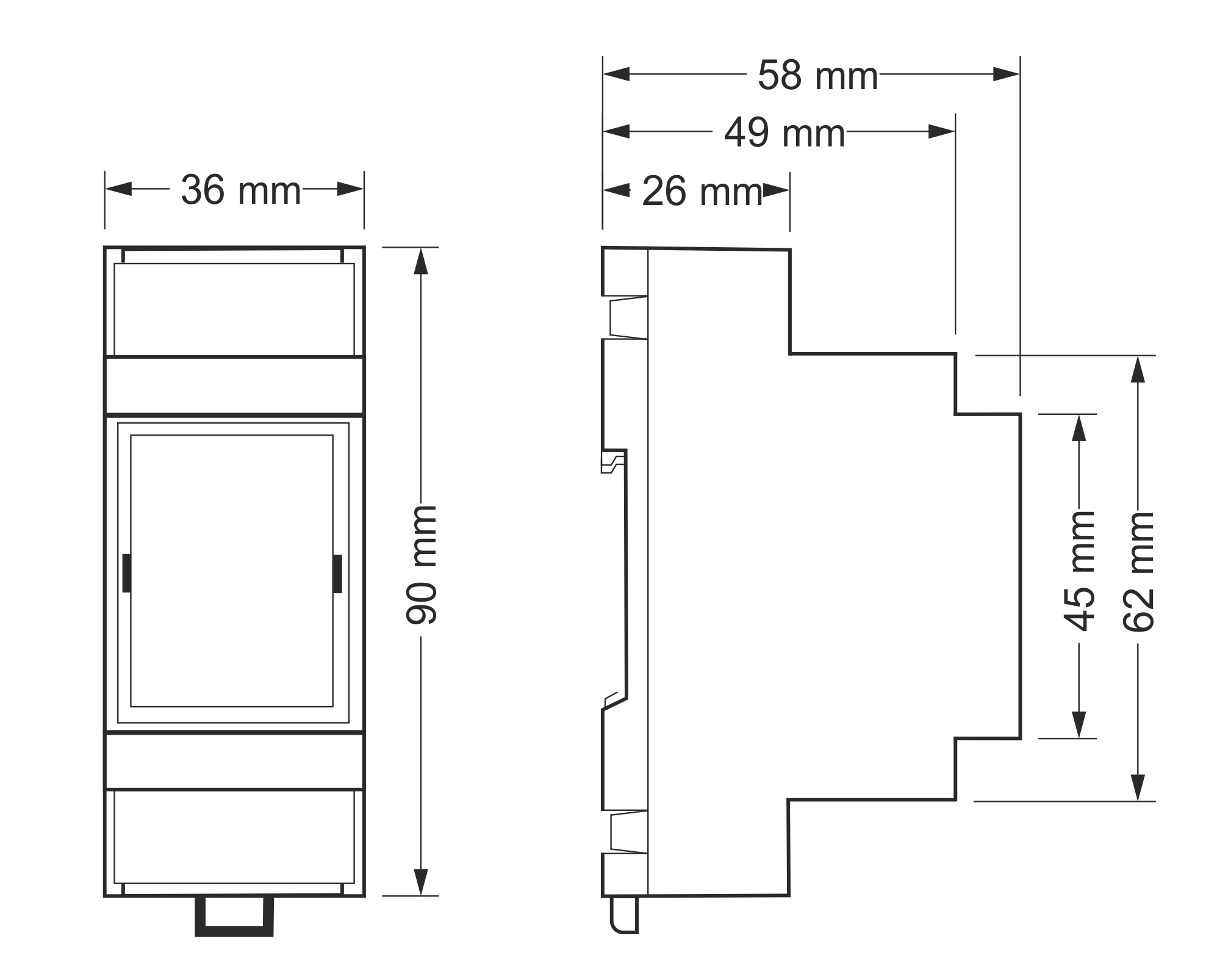 Overall dimensions