Documentation
WB-MCM8
8-channel pulse counter and digital input module
Covered order codes (1)
WB-MCM8— 8-channel pulse counter and digital input module
Purpose
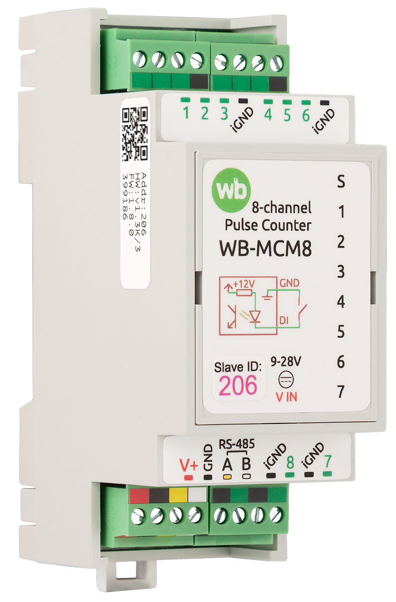
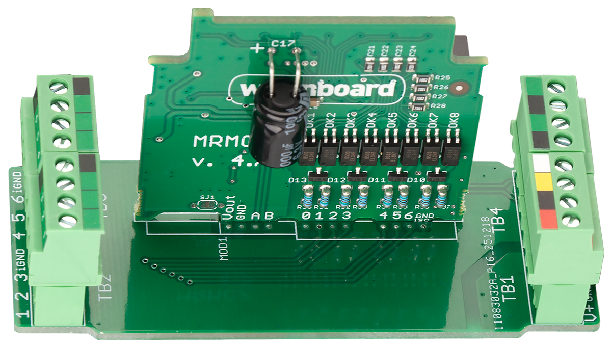
The WB-MCM8 is an eight-channel digital input and pulse counter module. Its inputs accept dry-contact and open-collector signals from push buttons, reed switches and similar devices for state monitoring and operation counting. The module can also count pulses from water, electricity and gas meters. Up to three quadrature encoders can be connected, with no more than two of them using the ABZ interface.
With push buttones, the module can distinguish four press patterns and send the corresponding events to a controller over Modbus: short, long, double, and short followed by long.
Technical specifications
| Group | Parameter | Value |
|---|---|---|
| Power | Supply voltage | 9–28 V DC |
| Power consumption | 0.1 W | |
| Inputs | Number of inputs | 8 |
| Input type and electrical limits | Dry contact, group isolation; approximately 12 V DC at the input; approximately 2 mA when closed; permissible external voltage −20 V to +40 V | |
| Functions | Pulse counting | 0 to 232−1 |
| Pulse frequency measurement | Supported | |
| Press recognition | Short, long, double, and short followed by long | |
| Encoder support | Up to three AB or ABZ quadrature encoders; no more than two ABZ encoders | |
| Pulse timing | Frequency and pulse duration | Up to 9 Hz (at least 50 ms) with default settings; up to 3.1 kHz (at least 0.2 ms) with debounce time set to 0 ms |
| Indication | Indicators | Status and input LEDs; see Indication |
| Control | Control interface | RS-485 |
| Interface isolation | Non-isolated | |
| Protocol | Modbus RTU; the address is software-configurable, and the factory settings are printed on the label | |
| Default RS-485 settings | 9600 bit/s, 8 data bits, no parity, 2 stop bits | |
| Startup | Ready after power-up | Approximately 2 seconds |
| Operating conditions | Ambient temperature | −40 to +80 °C |
| Relative humidity | Up to 95%, non-condensing | |
| Climatic category | O2.1* according to GOST 15150-69 | |
| Warranty / service life | 2 years / 8 years | |
| Terminals | Recommended conductor cross-section with insulated wire-end ferrules | 0.35–1 mm² for a single conductor; 0.35–0.5 mm² for twin crimping |
| Standard ferrule sleeve length | 8 mm | |
| Screw tightening torque | 0.2 N·m | |
| Dimensions | DIN-rail width | 2 modules |
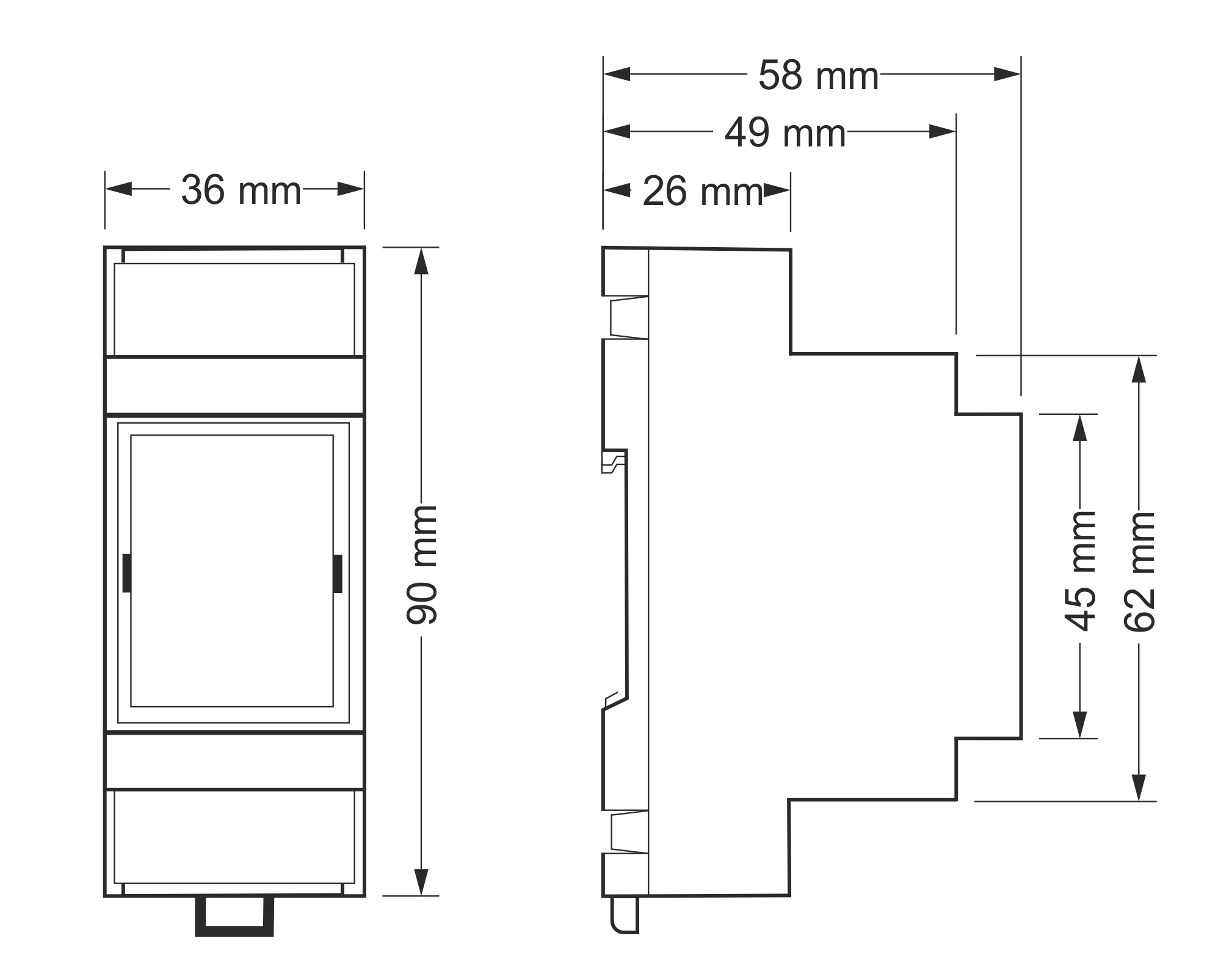
| Dimensions (L × W × H) | 36 × 90 × 58 mm | |
| Weight including packaging | 90 g |
Operating principle
Indication
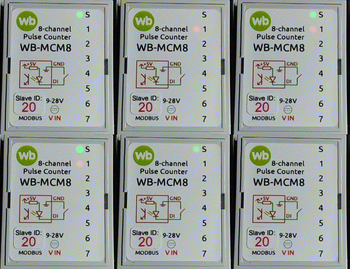
- S (green) indicates Modbus communication. It lights when low-voltage power is applied and flashes while the device is polled over RS-485. With Fast Modbus events enabled it flashes more frequently because event polling is faster than sequential polling. It flashes once per second in bootloader mode and rapidly during firmware upload.
- 1–7 (orange) show input state: an LED is on while its input is closed. Input 8 has no dedicated indicator.
Inputs
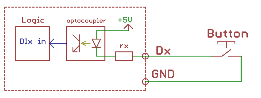
Each input operates as a dry-contact input. Connecting it to iGND activates the input. When a pulse arrives, the corresponding LED lights, the input state changes and that input’s operation counter increments. The 32-bit operation counters are stored in non-volatile memory.
The Debounce Time (ms) can be set separately for every input. In Count and frequency measurement mode the input also measures pulse frequency. The maximum 3.1 kHz measurement rate is available when the debounce time is 0 ms.
Press-pattern recognition
Press recognition is active when an input is set to Counting and press detection. The module recognises short, long, double, and short-then-long presses. It transmits a separate counter for each press type over Modbus so controller rules can process events reliably. Recognition timing is configurable.
Installation
General recommendations
Mount the WB-MCM8 on a standard 35 mm DIN rail. It occupies two DIN modules. The 3.5 mm-pitch terminal block marked V+ GND A B connects the power supply and RS-485 bus. Use a correctly wired RS-485 trunk with suitable termination. If devices on the bus use different power supplies, connect their GND terminals together.
An input activates when connected to iGND. The current is low, approximately 2 mA, so virtually any push button or switch type is suitable. Cable length and cross-section are normally not critical, but twisted pair is recommended near power wiring: use one conductor for the signal and the other for iGND. Install and operate the module within its specified environmental and electrical-safety limits.
Connecting meters and buttons
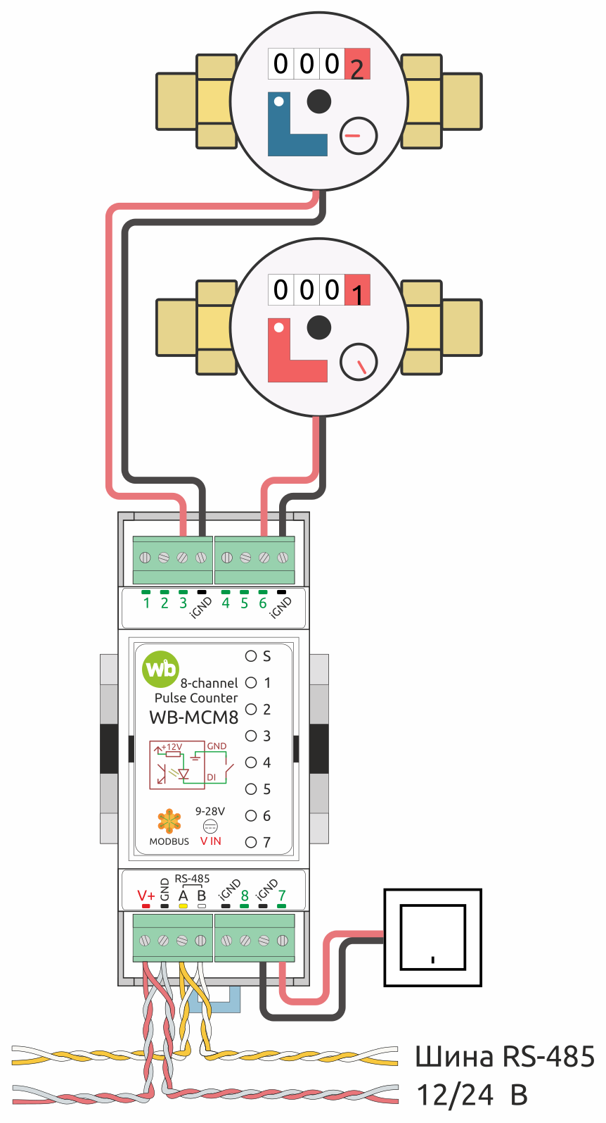
The example shows two dry-contact water meters connected to inputs 3 and 6 and a push button connected to input 7. Up to eight input devices can be connected. Where water consumption measurement must also trigger leak protection, use a purpose-built leak and water-control module such as the WB-MWAC.
Connecting encoders
Use the wiring diagram and input assignment in Encoder operation below.
Configuration
Configuration methods
You can configure the module in any of these ways:
- In a Wiren Board controller web interface under Settings → Configs → Serial device driver configuration. If these items are unavailable, check the current access level.
- By writing the module’s Modbus registers from the controller console with
modbus-utils-rpcormodbus_client. - Without a Wiren Board controller, by using the Wiren Board device web configurator or another Modbus tool on a computer with a USB-to-RS-485 adapter.
If a setting described here is missing, update the module firmware and controller software.
Input operating mode
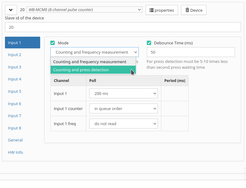
Set Mode separately for every input:
- Count and frequency measurement is intended for water, electricity and gas meters and other pulse-output devices. It is the default.
- Counting and press detection is intended for momentary push buttons and switches.
In both modes the module exposes Input X for the input state and increments Input X counter for every closure. For buttons, select press detection so events are reported immediately through Fast Modbus. In frequency mode, the controller polls the input in sequence with other bus devices and a state change can arrive later.
Count and frequency measurement
The module additionally reports pulse frequency in Input X freq. With the default debounce setting it counts pulses up to 9 Hz. Set Debounce Time (ms) to 0 for the maximum 3.1 kHz rate.
Counting and press detection
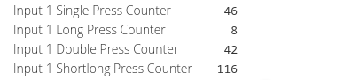
Each recognised pattern has its own counter:
Input X Single Press Counter— single short presses;Input X Long Press Counter— long presses;Input X Double Press Counter— double short presses;Input X Shortlong Press Counter— a short press followed by a long press.
Frequency is not measured in this mode. In automation rules, use the press counters instead of Input X: a short press may end before the controller reads the state, while the counter retains the event.
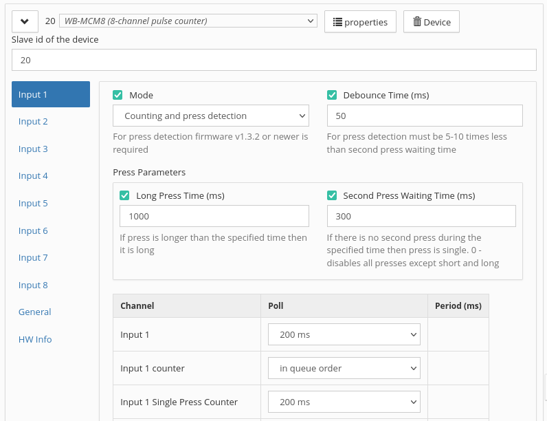
Available settings:
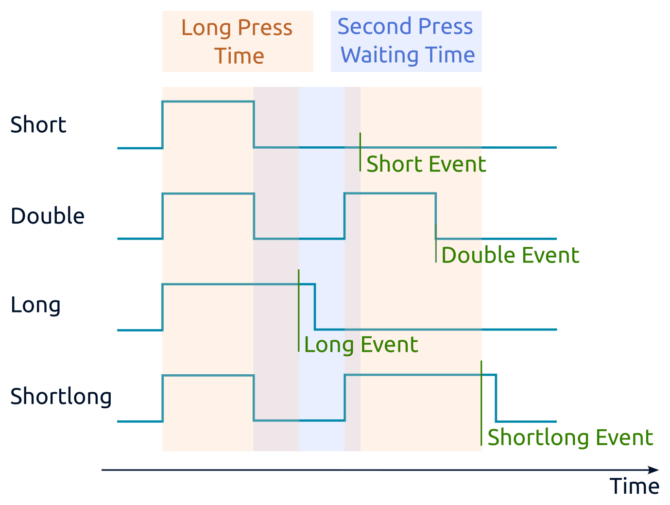
- Long Press Time (ms) separates long and short presses. A press longer than this value is long; otherwise it is short.
- Second Press Waiting Time (ms) opens a detection window after a short press is released. A second press within this window produces a double press; otherwise the first one is single.
- Debounce Time (ms) is the period for which the terminal signal must remain stable before the recognition algorithm accepts it. For buttons, use a value five to ten times shorter than the second-press wait time.
- Polling period for each press counter should normally remain at Default so the driver can select the correct polling method.
Double-press recognition delays single-press reporting. With the default 300 ms second-press window, a short-press event appears 300 ms after release. If double and short-then-long patterns are not required, set the wait time to 0 ms so a single press is reported immediately after release.
Recognition starts after debouncing. With the default 50 ms debounce, presses shorter than 50 ms are ignored and release is detected 50 ms after the physical release. Select the shortest value that suppresses false triggering for the actual switch.
Debouncing
Every input has a configurable Debounce Time (ms) filter. The permitted range is 0 to 2000 ms; the default is 50 ms.
Encoder operation
The WB-MCM8 accepts up to three quadrature (incremental) encoders, no more than two of which may be ABZ devices. These can be mechanical knob encoders for tasks such as light-level control or precision optical encoders for monitoring movement.
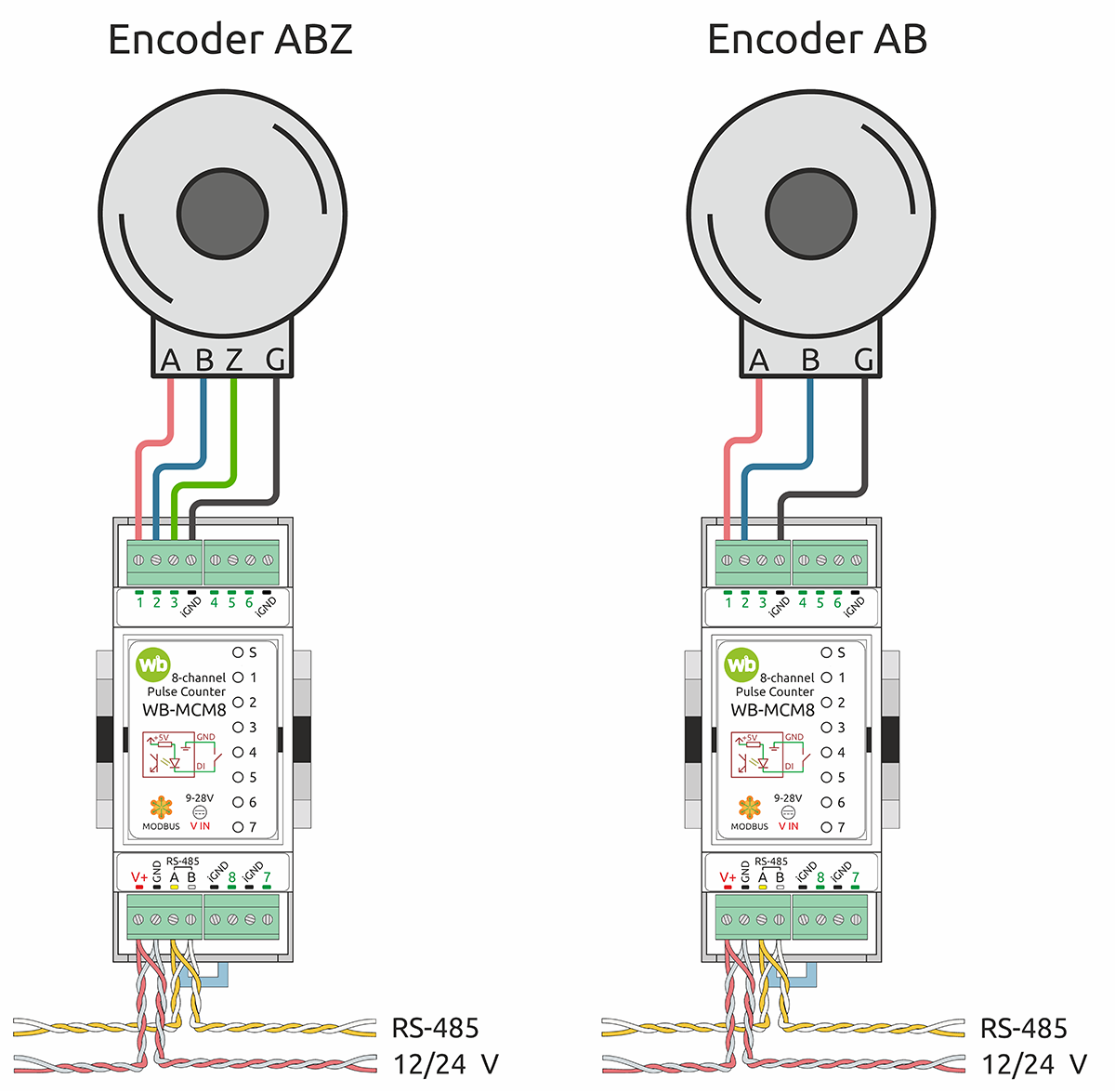
An encoder produces two pulse trains, A and B, with a phase offset. Pulse count determines the amount of shaft movement, and the signal that arrives first determines direction. An ABZ encoder adds a Z signal with one pulse per revolution, allowing the module to count complete revolutions.
Each encoder must use one input group on a single terminal block. An ABZ device can be assigned only as encoder 1 or encoder 2. Inputs not used by encoders remain available for ordinary pulse counting or button handling.
| WB-MCM8 input | Encoder | Signal |
|---|---|---|
| 1 | 1 | A |
| 2 | B | |
| 3 | Z | |
| iGND | GND (G) | |
| 4 | 2 | A |
| 5 | B | |
| 6 | Z | |
| iGND | GND (G) | |
| 7 | 3 | A |
| 8 | B | |
| iGND | GND (G) |
For every input used by an encoder, set Debounce Time (ms). The recommended value is 2–5 ms; use 2 ms for fast rotation.
AB encoders
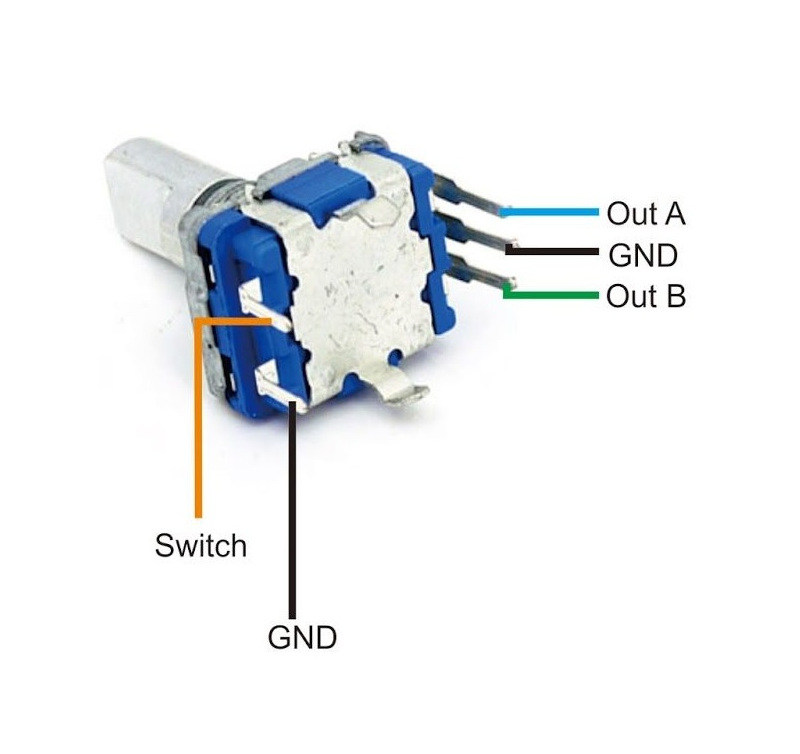
An AB encoder connects with three wires: A, B and GND. Shaft position is available in Encoder X position from −2,147,483,648 to 2,147,483,647. On overflow, the sign changes and counting continues. The position channel is writable, so it can be initialized to a chosen value.
Many mechanical encoders also provide a Switch output that closes to GND when the shaft is pressed. Connect it to any unused input and handle it as a regular push button.
ABZ encoders
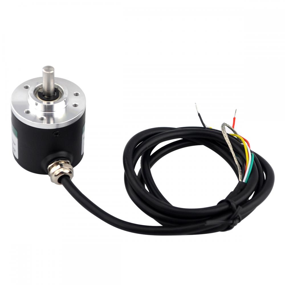
ABZ encoders are commonly used in industrial movement tracking. Four wires connect to A, B, Z and GND. The module exposes two data channels and one configuration parameter:
- Pulses per revolution is the encoder rating, such as 100 P/R or 2000 P/R, and determines the angle value within one revolution.
Encoder X anglereports shaft steps and direction within a revolution. When a Z pulse arrives, the value resets to 0 while rotating in the increasing direction, or becomes equal to Pulses per revolution while rotating in the decreasing direction.Encoder X revolutionsreports complete revolutions. It increments or decrements by one at every Z pulse according to direction.
The angle and revolution channels are writable and range from −32,768 to 32,767. On overflow, the sign changes and counting continues.
Configuring encoders
Encoder settings are under Encoders → Encoder 1, Encoder 2, Encoder 3. Select a Connection type:
- Not used — the default; all inputs operate independently in their selected modes.
- 2 signals, AB — the first two inputs of the group receive A and B; the third input, where present, remains available.
- 3 signals, ABZ — the third input receives Z; available only for encoders 1 and 2.
An input’s individual operating-mode setting has no effect while that input is assigned to an encoder. For ABZ, also enter Pulses per revolution. If it remains 0, Encoder X angle can become negative when the shaft crosses a revolution boundary.
Wiren Board controller web interface
Selecting the template
Add the module to the controller’s Devices page either automatically with RS-485 device discovery or manually by selecting the WB-MCM8 template.
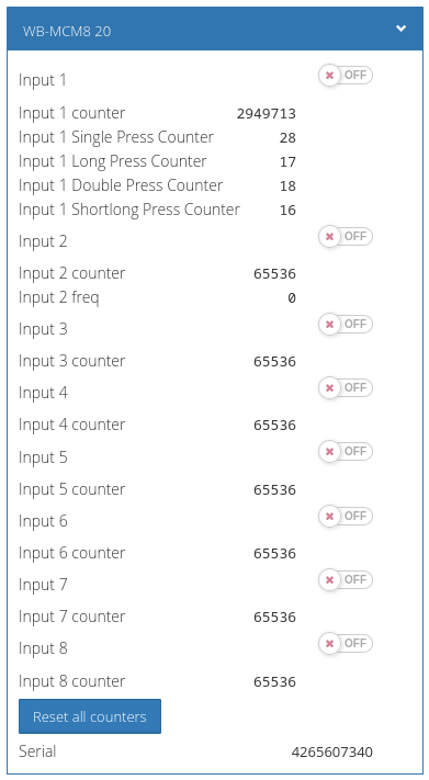
Viewing values and controlling the device
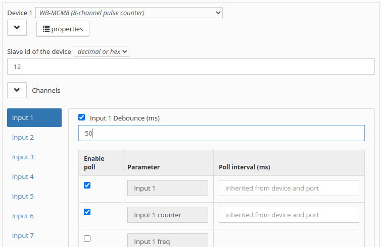
The web interface displays values received from the module. Choose which channels appear in the device settings of the wb-mqtt-serial driver.
Input 1throughInput 8show current input states and are read-only.Input 1 counterthroughInput 8 countercount every closure to iGND in either mode. They are stored in non-volatile memory and survive power cycling.Input X freqreports frequency in hertz only in count-and-frequency mode. It is not polled by default; enable polling in device settings if required.- Press-pattern counters are available in count-and-press-detection mode. They are stored in volatile memory and reset after power loss.
Encoder X position,Encoder X revolutionsandEncoder X angleappear when the corresponding encoder connection type is enabled.- Reset all counters clears all
Input X countervalues.
Modbus operation
The WB-MCM8 uses Modbus RTU over RS-485. It supports the standard commands for reading and writing one or more registers. Configure it in the Wiren Board controller web interface, the device web configurator, or compatible third-party software.
Default serial-port parameters
| Default | Web-interface name | Parameter |
|---|---|---|
| 9600 | Baud rate | Speed, bit/s |
| 8 | Data bits | Number of data bits |
| None | Parity | Parity |
| 2 | Stop bits | Number of stop bits |
With current firmware, the module also communicates correctly when its stop-bit setting differs from that of the Modbus master. For faster response, a data rate of 115,200 bit/s is recommended where the bus installation supports it.
Modbus address
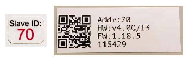
Every device on one line must have a unique address from 1 to 247. The factory address appears on labels on the top cover, side or bottom of the enclosure. Devices supplied together are normally assigned different factory addresses. The address can be discovered, changed or reset with Wiren Board controller tools or compatible Modbus configuration software.
Fast Modbus extension
Fast Modbus adds rapid discovery of Wiren Board devices on an RS-485 bus and event polling to standard Modbus. A master enables the extension with a special command, so the module remains compatible with ordinary third-party Modbus equipment. Only selected registers generate events; these are marked with a lightning symbol in the register map.
Register map
The WB-MCM8 register map in the installed device template defines all live values, counters and configuration registers. Use the template matching the installed firmware version.
Firmware update and factory reset
Firmware can be updated over Modbus, allowing fixes and technically compatible features to be deployed without removing the module. Configuration stored in device memory is retained during a firmware update. Controller tools also provide operations for resetting settings, changing connection parameters or the Modbus address, and updating the bootloader.
Known issues
Before deployment, check the current firmware release notes for known issues affecting the installed hardware revision. Keep firmware and the controller’s device templates up to date.
Hardware revisions
Hardware can change during the product lifetime. Identify the revision printed on the module and apply revision-specific service information when replacing devices or comparing terminal layouts.
Dimensions