 Documentation
WB-MCM8HV
8-channel mains-voltage presence detector with RS-485 Modbus RTU
Covered order codes (1)
WB-MCM8HV— 8-channel 230 V AC presence detector with RS-485 Modbus RTU
- hardware revision changes;
- firmware changes.
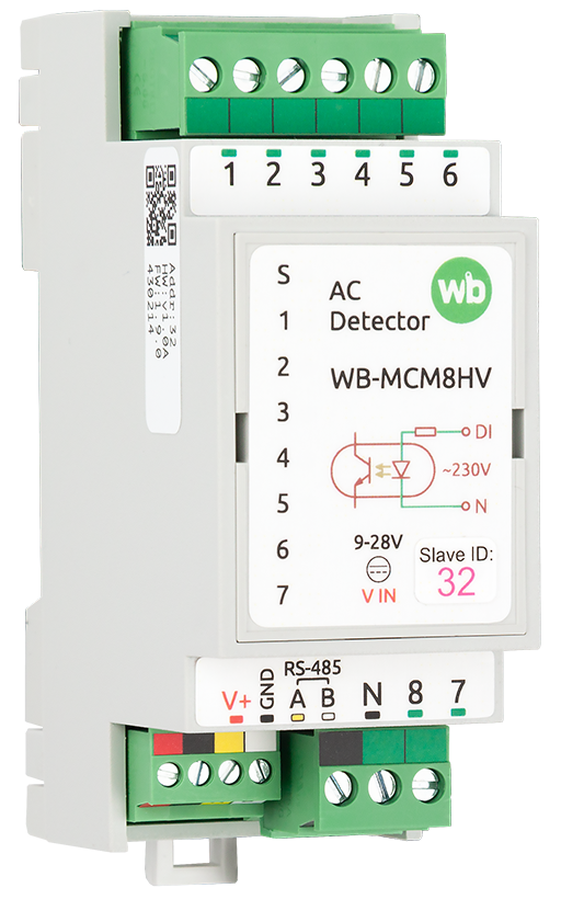
Purpose
The 8-channel mains-voltage presence detector with an RS-485 interface is designed for monitoring circuit-breaker states, reading indicator lamps and similar applications.
Technical specifications
| Parameter | Value |
|---|---|
| Power supply | |
| Supply voltage | 9–28 V DC |
| Power consumption | < 0.8 W |
| Inputs | |
| Number of inputs | 8 |
| Input type | Voltage input |
| Input isolation | Group isolation (one group of 8 inputs) |
| Activation voltage | 150 V AC or higher |
| Permissible voltage | Up to 260 V AC |
| Input activation current | 0.3 mA at 230 V AC |
| Isolation voltage between the input and the controller | 5000 V rms |
| Input activation time | Up to 2000 ms, configurable |
| Functions |
|
| Indicators | |
| LED | See Indication below |
| Control | |
| Control interface | RS-485 |
| Interface isolation | Non-isolated |
| Communication protocol | Modbus RTU; software-configurable address; factory settings are printed on the label |
| RS-485 interface parameters | Software-configurable; defaults:
baud rate — 9600 bit/s; data — 8 bits; parity — none (N); stop bits — 2 |
| Ready after power-on | ~2 s |
| Operating conditions | |
| Ambient air temperature | −40 to +80 °C |
| Relative humidity | Up to 95%, non-condensing |
| Climatic classification under GOST 15150-69 | O2.1* |
| Warranty | 2 years |
| Service life | 8 years |
| Terminal blocks and wire cross-sections | |
| Recommended wire cross-section with insulated wire-end ferrules | RS-485 terminal block: 0.35–1 mm2 — single ferrule; 0.35–0.5 mm2 — twin ferrule,
inputs: up to 2.5 mm2 — single ferrules; up to 1.5 mm2 — twin ferrule |
| Standard ferrule sleeve length | 8 mm |
| Screw tightening torque | RS-485 terminal block: 0.2 N·m;
inputs: 0.5 N·m |
| Dimensions | |
| Width, DIN modules | 2 |
| Overall dimensions (L × W × H) | 36 × 90 × 58 mm |
| Weight (including box) | 98 g |
Operating principle
Indicators
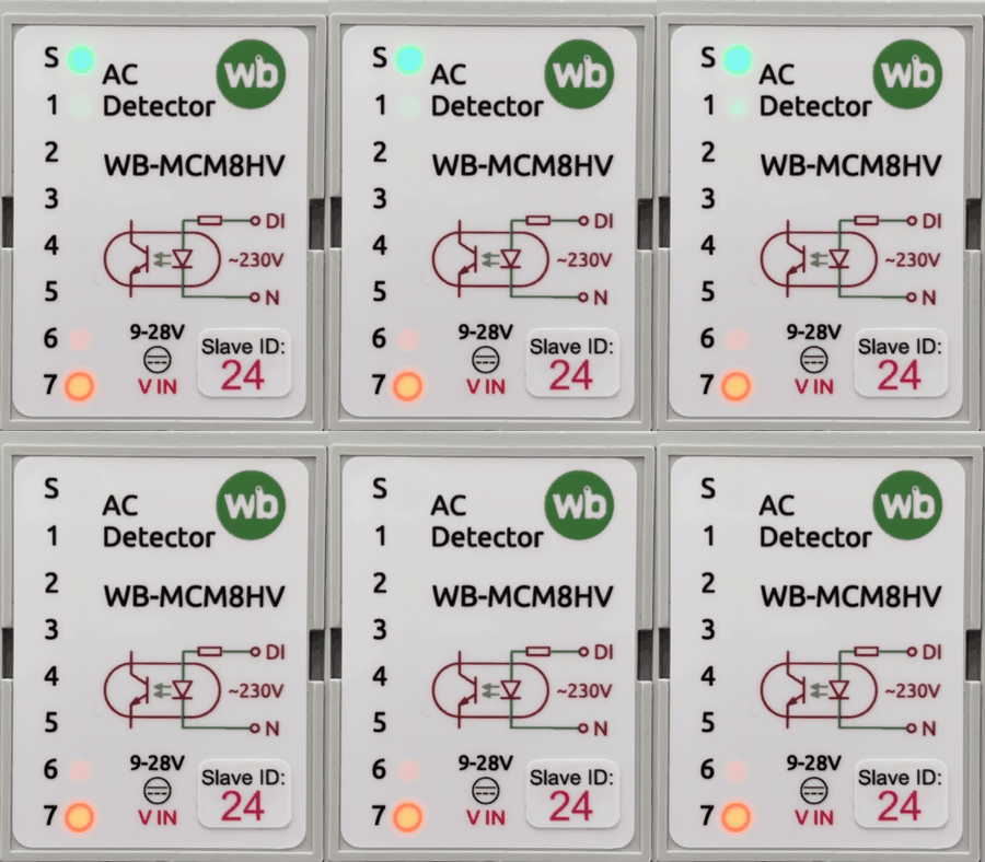
The module has indicators that show its status without connecting to a controller:
- S (green) indicates Modbus communication. It lights when low-voltage power is present and flashes during RS-485 polling. With Fast Modbus events enabled it flashes more frequently. It flashes once per second in bootloader mode and rapidly during firmware upload.
- 1–7 (orange) — input states. An LED lights when its input voltage exceeds 150 V. There is no LED for input 8.
Inputs
Inputs WB-MCM8HV activate when more than 150 V AC is present between an input terminal and terminal N.
The debounce time can be configured independently for each input from 0 to 2000 ms.
Installation
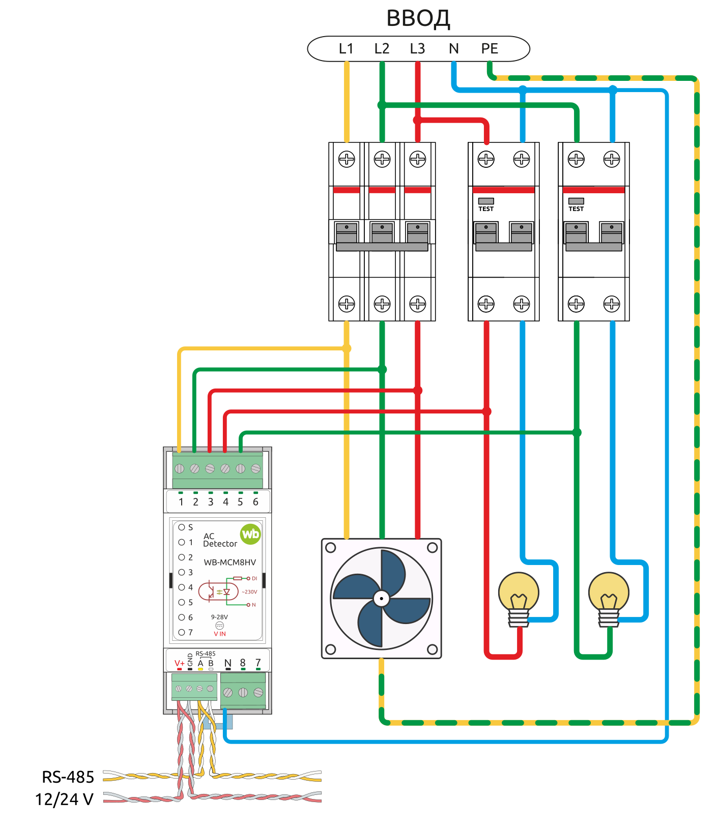
General recommendations
WB-MCM8HV mounts on a standard 35 mm DIN rail and occupies two DIN modules.
The 3.5 mm-pitch V+, GND, A and B terminal block connects power and the RS-485 bus. Correct RS-485 wiring is essential for reliable communication.
If devices on the RS-485 bus use different power supplies, interconnect their GND terminals.
Connect each input between the phase conductor of the monitored circuit and terminal N, which is common to all eight inputs. Connect terminal N to the neutral conductor of the same network being monitored. The module can detect voltage presence in 380/400 V three-phase networks.
Channel input current is approximately 0.3 mA at 230 V AC. Inputs on one module may therefore monitor circuits protected by different residual-current devices or RCBOs without tripping them.
Wiren Board controller web interface
Selecting a template
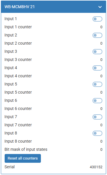
To display the device on the Devices in the Wiren Board controller web interface, add it with automatic RS-485 device discovery or select the template manually: WB-MCM8HV.
Controlling the device and viewing values
The web interface displays values received from the device. Change the visible channel list in the wb-mqtt-serial driver settings.
Switches Input 1 — Input 8 show the current input states and are read-only.
Counters Input 1 Counter — Input 8 Counter count all input activations regardless of press type. Counter values are stored in non-volatile memory and survive a power cycle.
Parameter Bit Mask of Input States reads every input state from one register. The decimal value represents a number assembled from the individual input-state bits.
Configuration
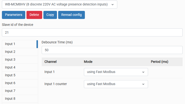
Configuration methods
- Set the parameters in the Wiren Board controller web interface under Settings → Configs → Serial devices driver configuration. If these options are unavailable, check the account access level.
- Write settings to the module's Modbus registers from the controller console with modbus-utils-rpc or modbus_client.
- Without a Wiren Board controller, use the Wiren Board web-based device configurator or other Modbus software. A computer with a USB-to-RS-485 adapter is required.
Our devices are continually improved. If settings described in this manual are missing, update the device firmware and controller software.
Debouncing
Configure input debouncing using the parameter Debounce Time (ms). The range is 0–2000 ms and the default is 50 ms. The setting suppresses false input activation caused by induced voltage, for example during equipment start-up, as well as push-button contact bounce.
Activation and button press counters
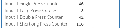
The module can detect different press types from push-buttons that switch mains voltage. Each input provides separate press-type counters, where N is the input number:
- Input N Single Press Counter — single short presses,
- Input N Long Press Counter — long presses,
- Input N Double Press Counter — double short presses,
- Input N Shortlong Press Counter — short-then-long presses.
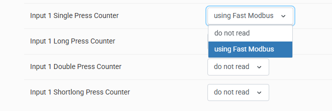
These channels count recognised press types rather than raw input activations. Enable polling for the corresponding channels before using press types in wb-rules.
The counters Input N Counter and Input N Single Press Counter perform similar functions but process activations differently:
- Counter increments as soon as voltage is applied to the input, after the configurable debounce interval;
- Single Press Counter increments when a short press has been detected without a second press. The response time is the short-press duration plus the second press waiting time.
Therefore, when using Single Press Counter to count discrete signals, you may need to shorten the second-press waiting time. Use Counter for pulse counting and the press-type counters for push-buttons.
Counting and press detection
The following settings are available for press-type counting and detection:
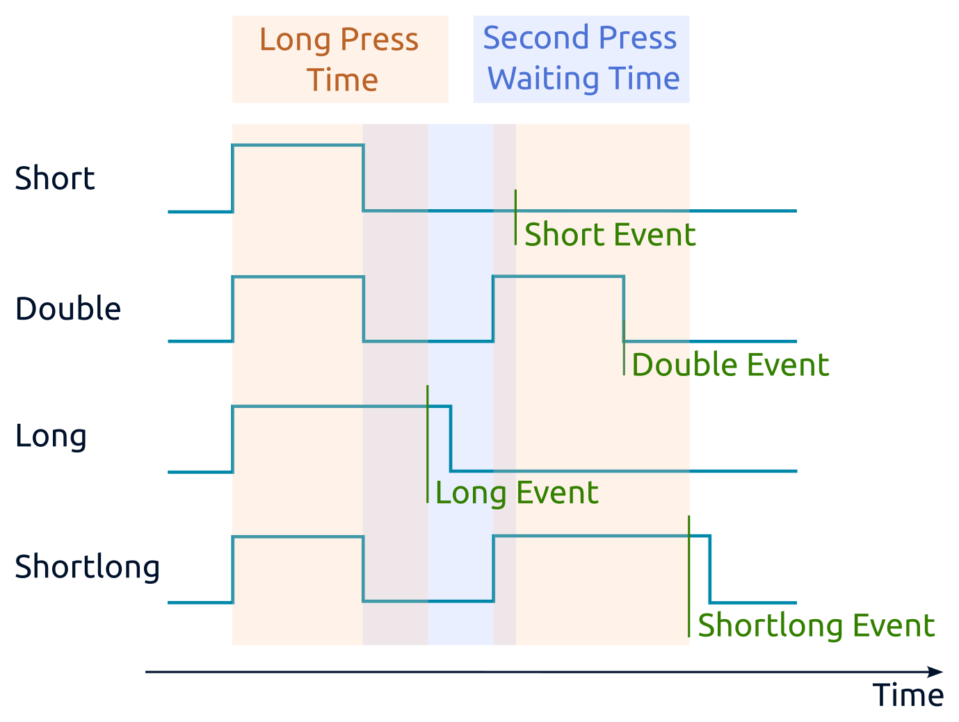
- Long Press Time (ms) — distinguishes long and short presses. A press lasting longer than this value is long; otherwise it is short.
- Second Press Waiting Time (ms) — opens a time window after a short press ends. A second press within this window is treated as a double press; otherwise the first press is treated as a single press.
- Debounce Time (ms) — the input signal must remain stable for this duration before it is accepted and processed by the press-recognition algorithm. For press recognition, set it to one fifth to one tenth of the second press waiting time.
- Polling interval for each counter — leave this at the default value; the driver manages polling automatically.
Double-press detection delays short-press detection. For example, with the default 300 ms setting, the short-press event occurs 300 ms after the button is released. If double presses and short-then-long presses are not required, set Second Press Waiting Time (ms) to 0 ms. The short-press event will then occur immediately after button release.
Press recognition takes place after debouncing. With Debounce Time (ms) set to the default 50 ms, presses shorter than 50 ms are ignored. Button release is also registered 50 ms after physical release. Choose the debounce time for the particular button to minimise latency while preventing false events, such as a double press being detected instead of a single press.
Modbus operation
Wiren Board devices use Modbus RTU over the RS-485 physical interface.
All standard commands for reading and writing one or more registers are supported.
The module can be configured:
- in the Wiren Board controller web interface;
- with the Wiren Board web-based device configurator;
- with third-party software.
Default port settings
| Value default |
Parameter name in the web interface |
Parameter |
|---|---|---|
| 9600 | Baud rate | Baud rate, bit/s |
| 8 | Data bits | Number of data bits |
| None | Parity | Parity |
| 2 | Stop bits | Number of stop bits |
In current firmware, setting Stop bits is optional: the device also operates correctly when its number of stop bits differs from the Modbus master setting.
For a faster response, we recommend increasing the baud rate to 115200 bit/s; configure the same communication parameters on the Modbus master
Modbus address
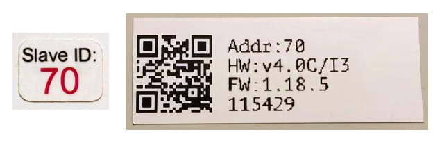
Each device on the bus must have a unique address from 1 to 247. The factory-assigned address is printed on labels on the enclosure (top cover, side or underside). Devices in a production batch are assigned different addresses, so devices in one order will usually have different addresses.
The address can be discovered, changed or reset with Wiren Board controller tools or compatible Modbus configuration software.
Fast Modbus extension
Fast Modbus extends standard Modbus with rapid discovery of Wiren Board devices on RS-485 and event polling.
These features are enabled by a special command from the master, so Wiren Board devices remain compatible with third-party equipment.
Not every register supports event generation. Check the register map: event-capable registers are marked with ⚡. See Fast Modbus.
Register map
WB-MCM8HV register map
Firmware updates and resetting settings
Wiren Board devices support firmware updates over Modbus. This allows bugs to be fixed at the installation site and, where technically possible, new features to be added. Settings stored in the device are retained during a firmware update.
Instructions:
- Firmware update (video tutorial)
- Resetting settings
- Connection parameter settings
- Modbus address: find, reset or change
- Updating the bootloader
Firmware releases are listed in the firmware changelog.
Known issues
Known issues
Hardware revisions
Revision history
Device images and drawings
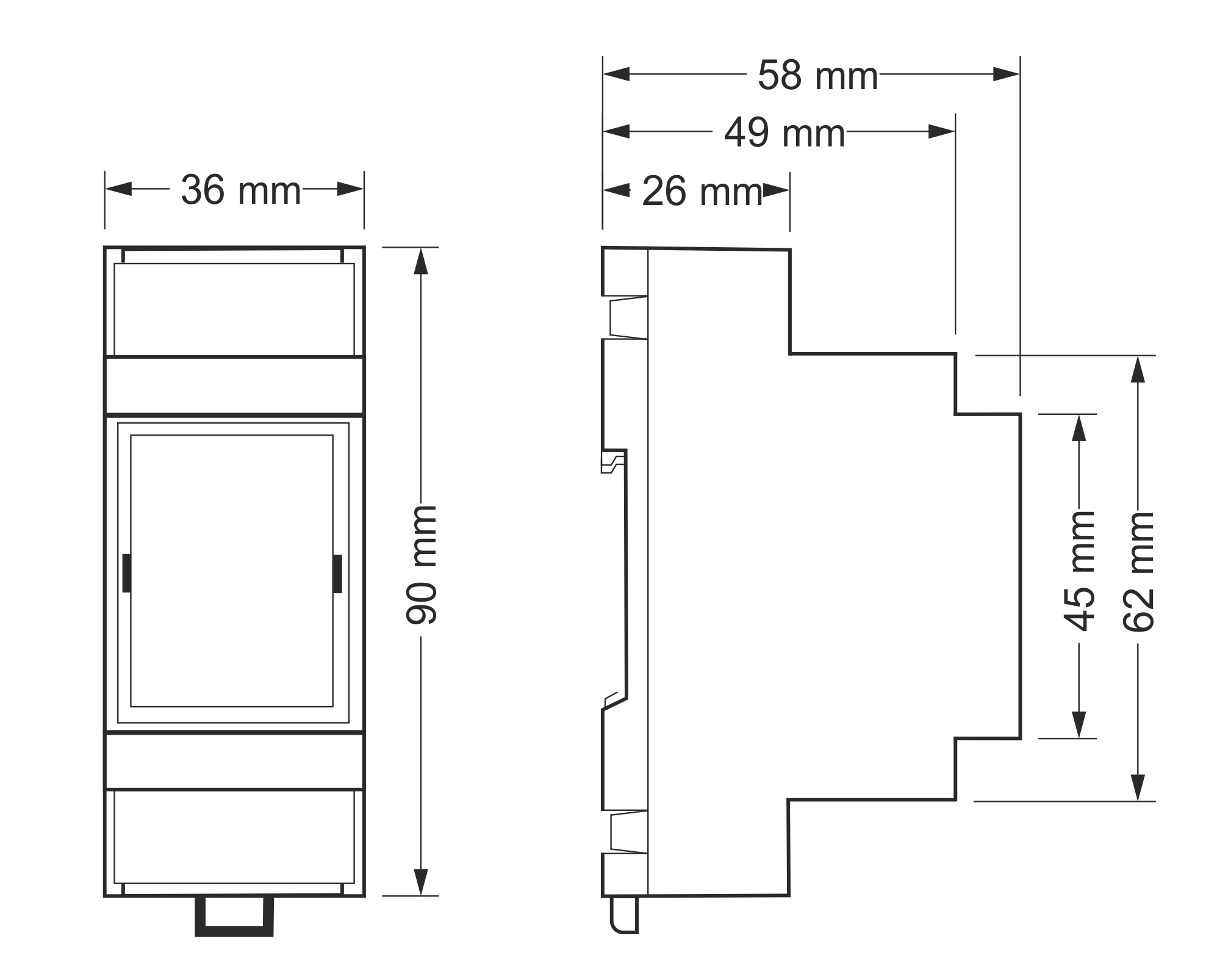
CorelDRAW 2018 (font: Ubuntu): File: WB-Library.cdr.zip
Visio:
- Wiren Board device stencil library for Visio.
- Third-party stencils for panels, circuit breakers, contactors and other equipment.
SVG: File: WB-Library.svg.zip
Module dimensional drawing (DXF): WB-MCM8HV dimensional drawing in DXF format
Module dimensional drawing (PDF): WB-MCM8HV dimensional drawing in PDF format
AutoCAD Electrical schematic symbol library: Wiren Board symbol library for AutoCAD Electrical