 Documentation
WBIO-DI-HVD-16
16-channel AC voltage detector
Covered order codes (1)
WBIO-DI-HVD-16
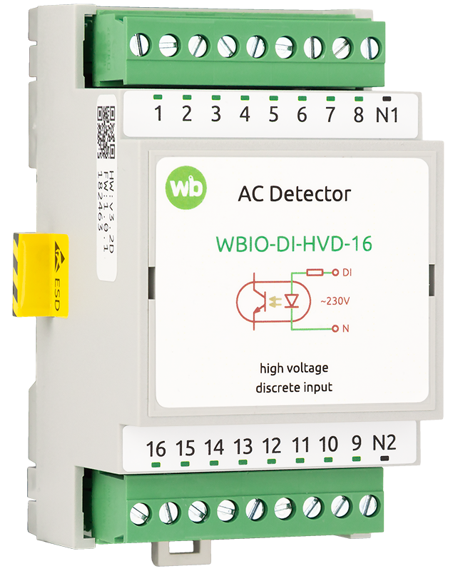
Purpose
The module is designed to monitor the state of circuit breakers, indicator lamps and similar equipment.
Technical specifications
| Parameter | Value |
|---|---|
| Number of inputs | 16 |
| Isolated input groups | 2 |
| Input type | Voltage input |
| Activation voltage | 110 V AC |
| Permissible voltage | Up to 260 V AC |
| Input activation current | 0.25 mA (at 230 V AC) |
| Resistive input impedance | 800 kΩ |
| Maximum response time (at 230 V AC) | 100 ms |
| Isolation voltage between the input and the controller | 5000 V rms |
| Module type | I (inverted addr.) |
| Maximum power consumption | 20 mW |
| Operating conditions | |
| Ambient air temperature | −40 to +80 °C |
| Relative humidity | Up to 95%, non-condensing |
| Climatic classification under GOST 15150-69 | O2.1* |
| Warranty | 2 years |
| Service life | 8 years |
| Compatibility | |
| Compatible controllers | Wiren Board 5, 6, 7, 8 |
| Compatible modules | WB-MIO, WB-MIO-E and WB-MGE v.3 interface modules |
| Terminal blocks and wire cross-sections | |
| Recommended wire cross-section with insulated wire-end ferrules | 0.5–2.5 mm2 |
| Standard ferrule sleeve length | 8 mm |
| Screw tightening torque | 0.5 N·m |
| Dimensions | |
| Width, DIN modules | 3 |
| Overall dimensions (L × W × H) | 53 × 90 × 58 mm |
| Weight (including box) | 115 g |
Operating principle
The module has 16 inputs for detecting the presence of AC mains voltage, with galvanic isolation by input group. The inputs are divided into two groups. The input activation voltage range is 110–260 V AC.
Installation
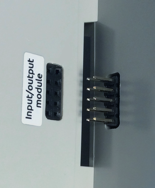
I/O modules connect to the right-hand side of a Wiren Board controller or a WB-MIO, WB-MIO-E or WB-MGE v.3 interface converter using the side connector. Make sure that every pin enters the corresponding socket. Secure the assembly on the DIN rail using end stops on both sides, but leave approximately 2 cm of free space to allow quick removal.
Up to eight modules can be connected in sequence: up to four input modules (type I) and up to four output modules (type O). The WBIO-AI-DV-12 is an exception: only one module of this model can be connected.
Addresses are assigned sequentially. Up to four modules can be connected in any order. For more than four modules, connect all modules of one type first, followed by all modules of the other type.
Wiring
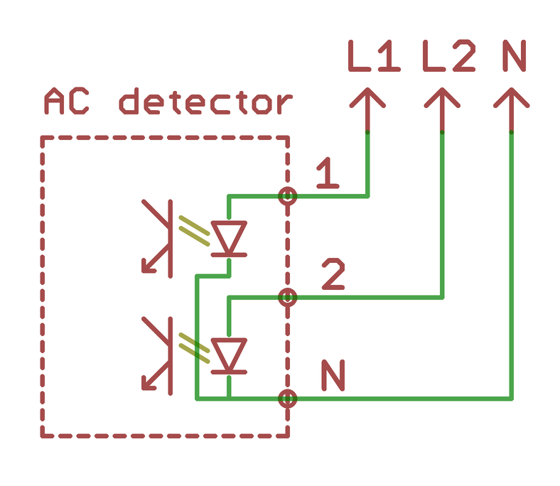
The inputs are divided into two mutually isolated terminal groups:
- (1, 2, 3, 4, 5, 6, 7, 8, N1) and (N2, 9, 10, 11, 12, 13, 14, 15, 16).
N1 and N2 are the common terminals for their respective input groups.
Configuration in the controller web interface
Configuration with a Wiren Board controller
After physically connecting the module, add it to the controller configuration:
- In the web interface, open Settings → Configs.
- Open Expansion modules and ports and select the WBIO module (External I/O module) slot corresponding to the connected WBIO side module.
- In the Module type list, select the type of module installed.
- Click Save.
WBIO modules do not support hot plugging.
To remove a module from the configuration, select Not installed.
Check that the external module is visible in the web interface:
- Open Devices.
- Find the Discrete I/O for digital modules, or ADCs for analog modules. Channel names follow the pattern EXTN_YYYY, where N is the module sequence number and YYY is the module channel name.
The MQTT topic address follows the pattern /devices/wb-gpio/controls/EXTN_YYYY.
-
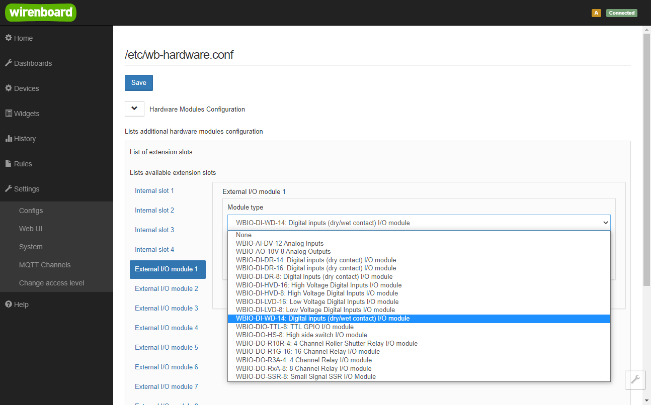 Configuring a new side module
-
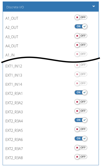 External module channels in the Wiren Board controller web interface
Configuration with WB-MIO
Configuration with WB-MGE v.3
Known issues
Hardware revisions
The batch number is printed on a label on the side of the enclosure or on the PCB.
| Revision | Batches | Release date | Changes from the previous revision |
|---|---|---|---|
| 3.2 | v3.2D/1, v3.2E - ... | 09.2026 - ... |
|
| 3.2 | v3.2B, v3.2C, v3.2C/1, v3.2D | 10.2025 - 09.2026 |
|
| 3.2 | v3.2A, v3.2B/1 | 08.2025 - 10.2025 |
|
| 2.2 | v2.2L, v2.2M, v2.2N, v2.2O, v2.2P | 09.2023 - 08.2025 |
|
| 2.2 | v2.2A, v2.2B, v2.2C, v2.2D, v2.2E, v2.2F, v2.2G, v2.2H, v2.2I, v2.2J, v2.2K | 08.2019 - 03.2023 |
|
| 1.1 - 1.2 | 109, 129, 158 | 10.2016 - 08.2019 |
|
Device images and drawings
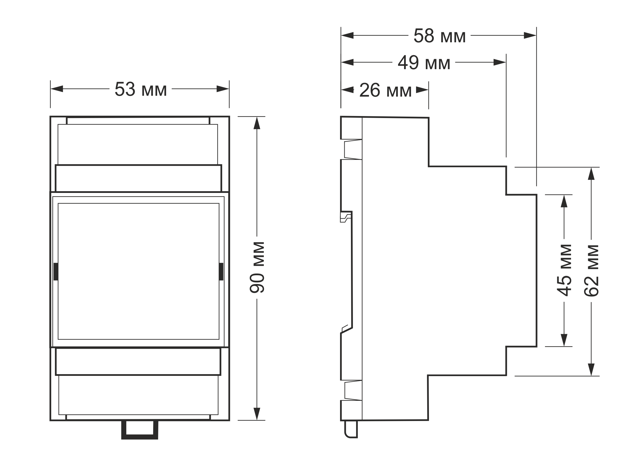
CorelDRAW 2018 (font: Ubuntu): File: WB-Library.cdr.zip
Visio:
- Wiren Board devices: File: WB-Visio-Lib.zip.
- Enclosures, circuit breakers, contactors and other third-party symbols.

Autocad 2013 DXF: File:WBIO-DI-HVD-16.dxf.zip