 Documentation
WB-MIR v.3
Infrared remote control module
Covered order codes (1)
WB-MIR v.3
This page describes the new WB-MIR v.3 device; for the previous version, see WB-MIR v.2.
This page describes the latest hardware revision with the latest stable firmware. If your device runs older firmware, update it where possible (see Firmware update).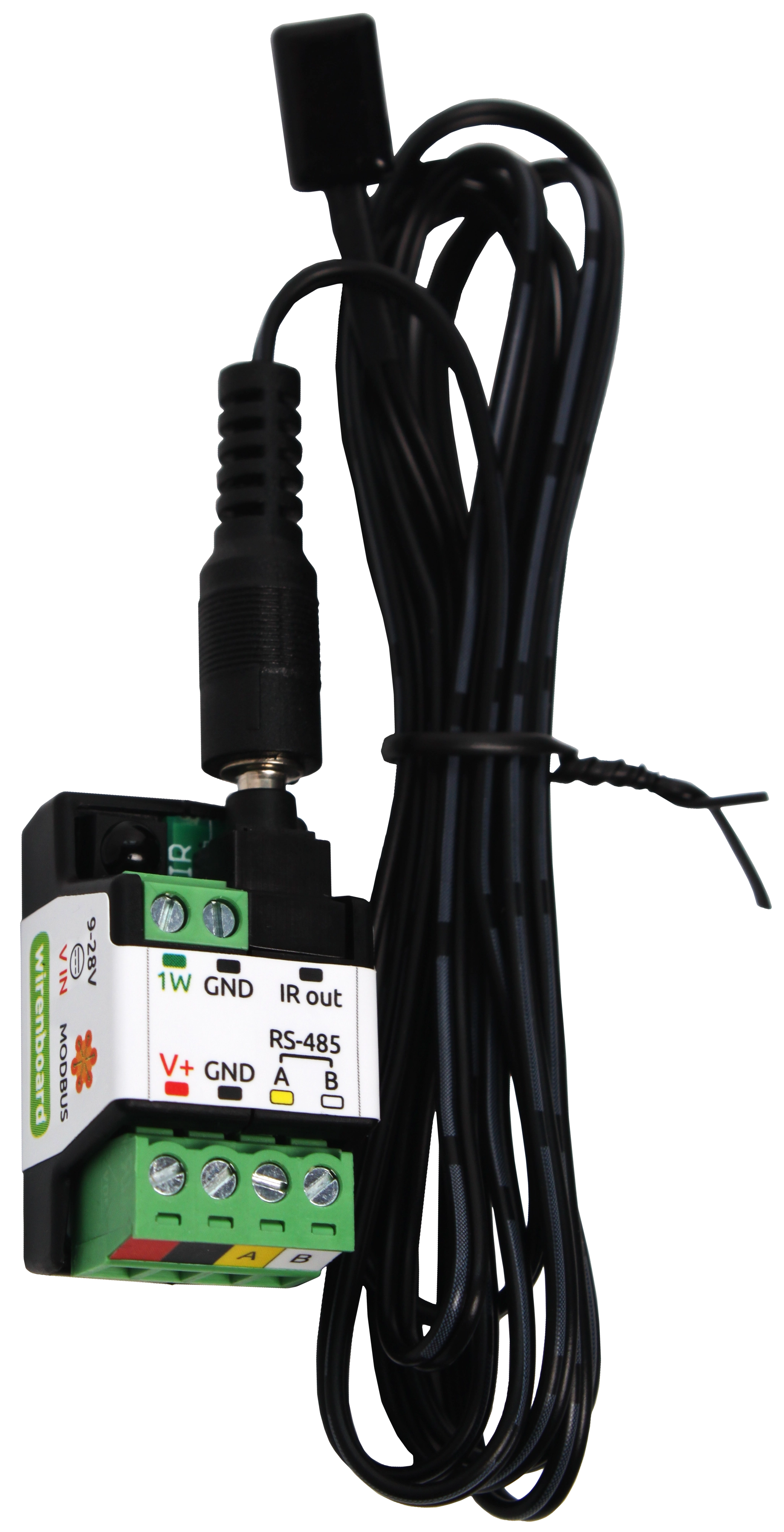
Purpose
A learning infrared transceiver module for controlling air conditioners, televisions and other IR-operated equipment. A controller or PC sends Modbus RTU commands over RS-485. It also supports up to 20 DS18B20 digital temperature sensors over 1-Wire, or use of the input for counting and press detection.
Technical specifications
| Parameter | Value |
|---|---|
| Power supply | |
| Supply voltage | 9–28 V DC |
| Power consumption |
0.1 W |
| Transmitter range | < 1 m |
| External sensors | Up to 20 DS18B20 digital temperature sensors. |
| IR commands | |
| Transmitter carrier frequency | 38 kHz |
| Number of stored commands | 80 |
| Command duration | Maximum command length: up to 1000 symbols.
Each register encodes the duration of a successive high or low signal level in microseconds; one unit equals 10 microseconds. |
| Control | |
| Control interface | RS-485 |
| Interface isolation | Non-isolated |
| Communication protocol | Modbus RTU; software-configurable address; factory settings are printed on the label |
| RS-485 interface parameters | Software-configurable; defaults:
baud rate — 9600 bit/s; data — 8 bits; parity — none (N); stop bits — 2 |
| Ready after power-on | ~2 s |
| Operating conditions | |
| Ambient air temperature | −40 to +80 °C |
| Relative humidity | Up to 95%, non-condensing |
| Climatic classification under GOST 15150-69 | O2.1* |
| Warranty | 2 years |
| Service life | 8 years |
| Terminal blocks and wire cross-sections | |
| Recommended wire cross-section with insulated wire-end ferrules | 0.35–1 mm2 — single ferrule; 0.35–0.5 mm2 — twin ferrule |
| Standard ferrule sleeve length | 8 mm |
| Screw tightening torque | 0.2 N·m |
| Dimensions | |
| L × W × H |
34 × 20 × 17 mm; the transmitter cable connector adds 30 mm to the enclosure width |
| Weight (including box) | 25 g |
Operating principle
Record a signal from the equipment's remote control into module memory, then play it back.
To record, point the remote at the module receiver labelled IR. To transmit, connect the external IR emitter to IR out (3.5 mm) and position it over the controlled equipment's IR receiver.
Input 1W accepts up to 20 external temperature sensors DS18B20 or change the input mode to use it for counting instead. Sensor values can monitor controlled equipment in wb-rules rules or Node-Red scenarios. For example, switch an air conditioner according to DS18B20 temperature readings.
Indicators
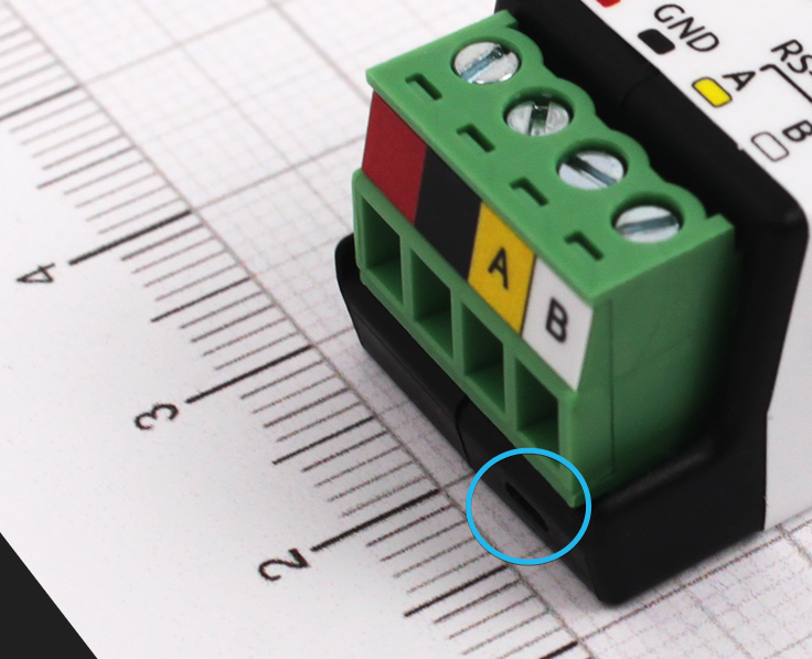
The module has an indicator that shows its status without connecting to a controller:
- S (green) — Modbus communication status: lights up when low-voltage power is applied and flashes during polling over RS-485. On devices with events enabled in Fast Modbus ⚡ the indicator flashes more frequently than during sequential polling because events are polled faster. In bootloader mode, it flashes once per second; during firmware upload, it flashes rapidly. It is located beneath terminal B.
Press-type recognition
The module recognises four press types: short; long; double; and short followed by long.
Presses can be processed on the controller, which receives a separate counter for each press type over Modbus.
Press-recognition parameters can be changed in the settings.
Press counters and input states can be received as Fast Modbus events, minimising latency regardless of bus load. See Modbus operation.
Example rule for processing press counters
Installation
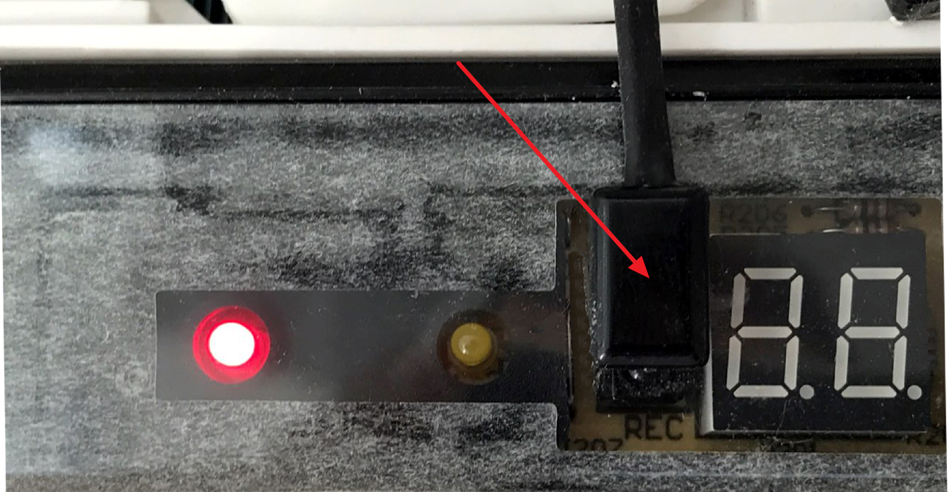
Install the module near or inside the controlled equipment, such as an air conditioner. Keep it accessible if further IR learning will be needed. Attach the emitter on its approximately 140 cm cable beside the equipment's receiver using the supplied double-sided tape. Do not completely obscure the receiver if the original remote must remain usable. Verify reliable IR transmission.
The V+ GND A B terminal block, with a 3.5 mm pitch, connects the power supply and RS-485 communication bus. Correct bus wiring is essential for reliable communication; see RS-485 bus wiring and connection.
If devices on the RS-485 bus use different power supplies, their GND terminals must be interconnected. See Grounding Wiren Board devices and connecting GND and iGND.
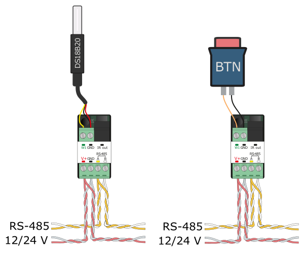
External temperature sensors, up to 20 DS18B20 connect to WB-MIR v.3 using parasitic power: join each sensor's +5 V and GND leads to the GND terminal, and connect DATA to 1W.
The 1-Wire input also accepts a dry-contact sensor. When using one, change the input operating mode from 1-Wire to digital input.
Wiren Board controller web interface
Selecting a template
To display the device on the Devices tab of the Wiren Board controller web interface, add it automatically by scanning for Wiren Board devices on RS-485 or manually by selecting the template WB-MIR v.3.
Controlling the device and viewing values
The web interface allows you to control device outputs and view readings. To change the displayed channels, edit the device configuration in the wb-mqtt-serial driver settings.
Main WB-MIR v.3 controls:
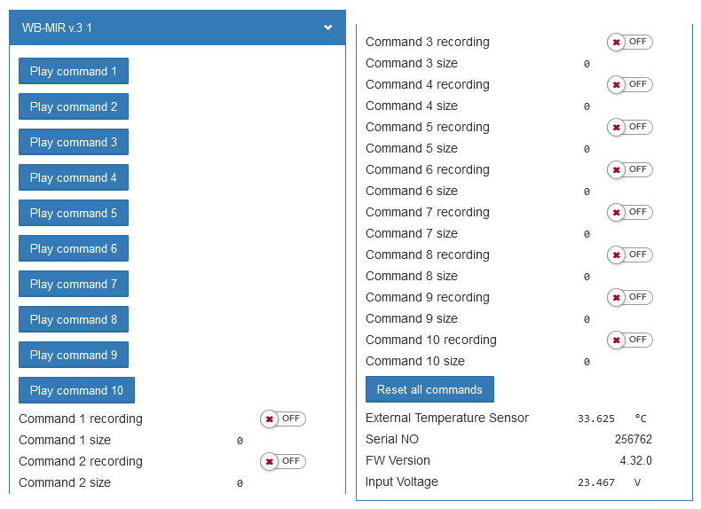
- Command x recording — record IR command x;
- Command x size — stored command x length, indicating successful recording;
- Play command x — transmit IR command x;
- Reset all commands — erase every recorded command. Caution: this button erases commands without asking for confirmation!;
- Internal/External Temperature Sensor — internal/external digital sensor temperature. Missing or faulty sensors are highlighted in red;
- Serial NO — WB-MIR serial number, which may be required for technical support;
- FW Version — firmware version;
- Input Voltage — module supply voltage.
Configuration
Configuration methods
- Set the parameters in the Wiren Board controller web interface under Settings → Configs → Serial devices driver configuration. If these items are unavailable, check your access level.
- Write settings to the Modbus registers of the module from the controller console using the utility modbus-utils-rpc or modbus_client.
- Without a Wiren Board controller, use the Wiren Board device web configurator or other software; see Using Wiren Board Modbus devices without a controller. You will need a computer with an interface converter: USB-RS485.
Our devices are continually improved. If settings described in this manual are missing, update the device firmware and controller software.
Learning IR commands and using the module
The learning receiver is located directly beside the dark-lens receiver labelled IR.
For detailed WB-MIR v.3 operation, see Using the IR transceiver in WB-MSW and WB-MIR.
For third-party Modbus masters such as SCADA, OPC servers or other PLCs, use holding registers 5500/5501/5502 instead of coils; see Working with signals through holding registers.
1W input operating mode
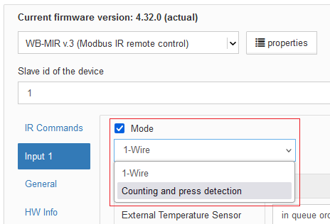
Configure 1W as a 1-Wire interface or a counting/press-detection input. Enable the input by selecting Mode, then choose its type from the drop-down list.
Counter data is written to non-volatile memory when the value changes, but no more than once every 300 seconds. This keeps the stored counters up to date while extending the lifetime of the non-volatile memory.
Debouncing
Configure input debouncing using the parameter Debounce Time (ms) parameter. Range: 0–100 ms; default: 50 ms.
Counting and press detection
When you select the mode Counting and press detection, you can configure transmission of press counters to the controller. See Press-type recognition.
Available settings:
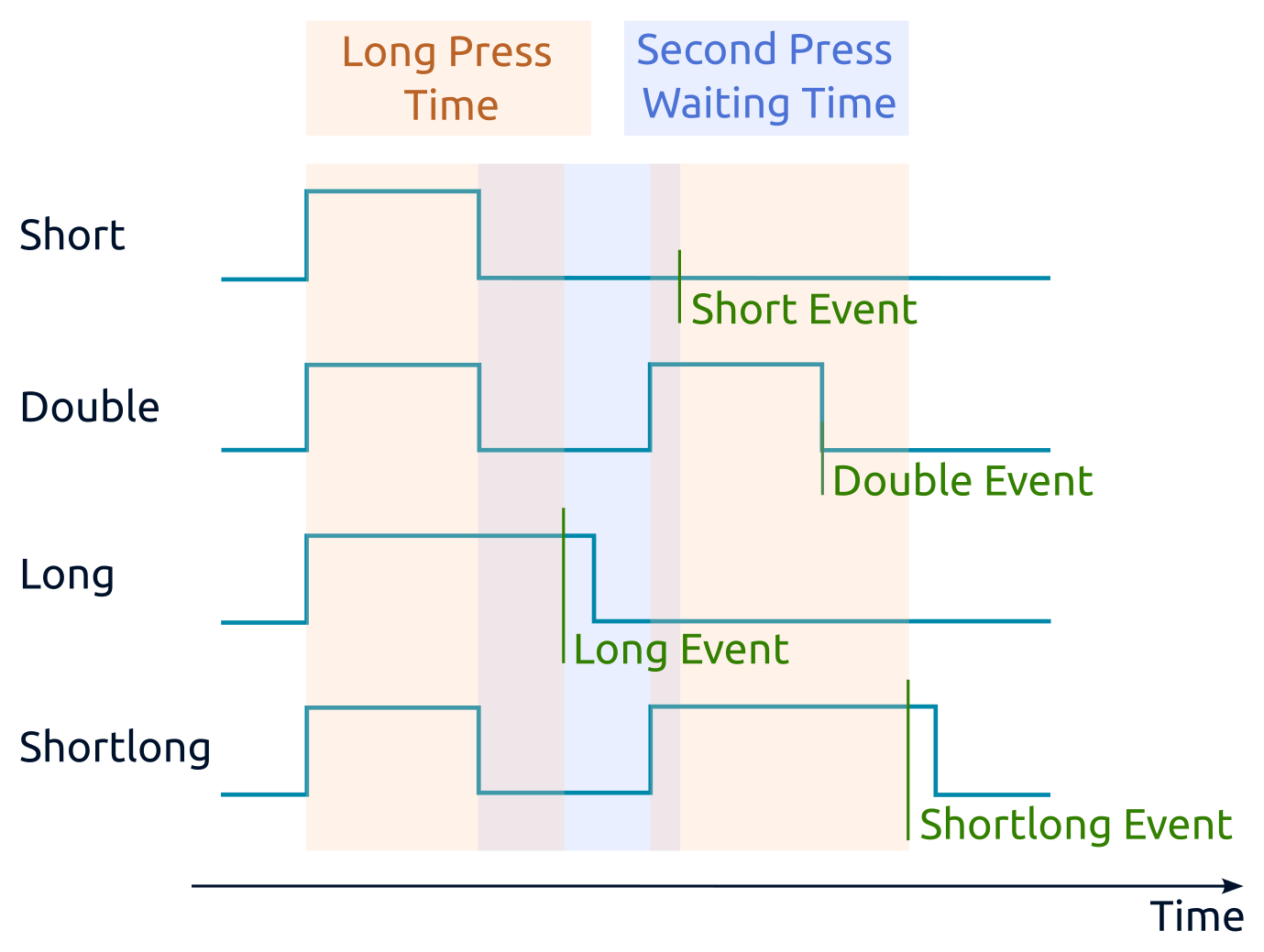
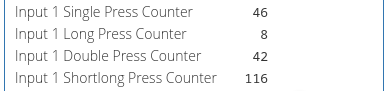
- Long Press Time (ms) — distinguishes long and short presses. A press lasting longer than this value is long; otherwise it is short.
- Second Press Waiting Time (ms) — opens a time window after a short press ends. A second press within this window is treated as a double press; otherwise the first press is treated as a single press.
- Debounce Time (ms) — the input signal must remain stable for this duration before it is accepted and processed by the press-recognition algorithm. For press recognition, set it to one fifth to one tenth of the second press waiting time.
- Polling interval for each counter — leave this at the default value; the driver manages polling automatically.
Double-press detection delays short-press detection. For example, with the default 300 ms setting, the short-press event occurs 300 ms after the button is released. If double presses and short-then-long presses are not required, set Second Press Waiting Time (ms) to 0 ms. The short-press event will then occur immediately after button release.
Press recognition takes place after debouncing. With Debounce Time (ms) set to the default 50 ms, presses shorter than 50 ms are ignored. Button release is also registered 50 ms after physical release. Choose the debounce time for the particular button to minimise latency while preventing false events, such as a double press being detected instead of a single press.
Safety Mode

Safety Mode can transmit an IR command once if control of the device is lost, for example after an RS-485 cable break. Account for communication loss in the system design.
The fail-safe timer restarts after every successfully received and processed Modbus packet. When the timeout expires, the device enters Safety Mode. Normal operation resumes when communication returns. The default timeout is 10 seconds.
The default fail-safe action is Do nothing. Select Play IR command and specify its command number to enable an action.
Modbus operation
Wiren Board devices use Modbus RTU. The physical connection uses the RS-485.
interface. All main commands for reading and writing one or multiple registers are supported. See the list in the Modbus protocol description.
The module can be configured:
- in the Wiren Board controller web interface;
- using the Wiren Board device web configurator;
- using third-party software.
Default port settings
| Value default |
Parameter name in the web interface |
Parameter |
|---|---|---|
| 9600 | Baud rate | Baud rate, bit/s |
| 8 | Data bits | Number of data bits |
| None | Parity | Parity |
| 2 | Stop bits | Number of stop bits |
In current firmware, setting Stop bits is optional: the device also operates correctly when its number of stop bits differs from the Modbus master setting.
For a faster response, we recommend increasing the baud rate to 115200 bit/s; see Communication parameter settings
Modbus address
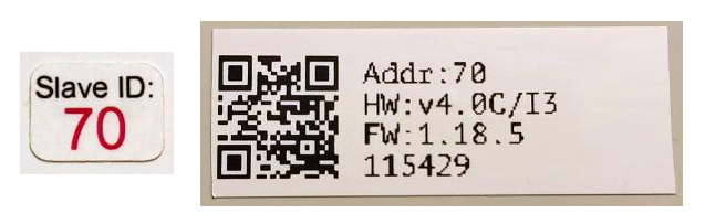
Each device on the bus must have a unique address from 1 to 247. The factory-assigned address is printed on labels on the enclosure (top cover, side or underside). Devices in a production batch are assigned different addresses, so devices in one order will usually have different addresses.
For instructions on finding, changing or resetting the address, see Wiren Board device Modbus address.
Fast Modbus extension
Fast Modbus extends standard Modbus with rapid discovery of Wiren Board devices on RS-485 and event polling.
These features are enabled by a special command from the master, so Wiren Board devices remain compatible with third-party equipment.
Not every register supports event generation. Check the register map: event-capable registers are marked with ⚡. See Fast Modbus.
Register map
This article contains general-purpose registers such as communication settings, firmware information and service registers. IR recording, playback and editing registers are documented separately in the Register map section of Using the IR transceiver.
Firmware updates and resetting settings
Wiren Board devices support firmware updates over Modbus. This allows bugs to be fixed at the installation site and, where technically possible, new features to be added. Settings stored in the device are retained during a firmware update.
Instructions:
- Firmware update ()
- Resetting settings
- Connection parameter settings
- Modbus address: find, reset or change
- Updating the bootloader
New firmware releases are listed in the firmware changelog.
Known issues
WB-MIR v.3 hardware issues and limitations identified during operation.
Hardware revisions
Device images and drawings
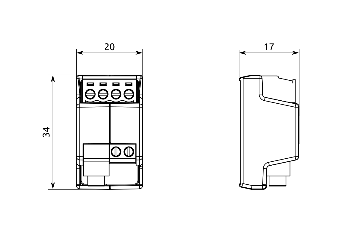
CorelDRAW 2018 (font: Ubuntu): File: WB-Library.cdr.zip
Visio:
- Wiren Board devices: File: WB-Visio-Lib.zip.
- Enclosures, circuit breakers, contactors and other third-party symbols.

Autocad 2013 DXF: File: WB-MIRv3.dxf.zip
Autocad PDF: File: WB-MIRv3.pdf
AutoCAD Electrical schematic symbol library: File: Wirenboard-AE-base.zip