 Documentation
WB-MWAC v.2
Water metering and leak detection module
Covered order codes (1)
WB-MWAC
This page describes the newer WB-MWAC v.2; for the previous version, see WB-MWAC v.1.
This page describes the latest hardware revision with the latest stable firmware. If your device runs older firmware, update it where possible (see Firmware update).
Purpose
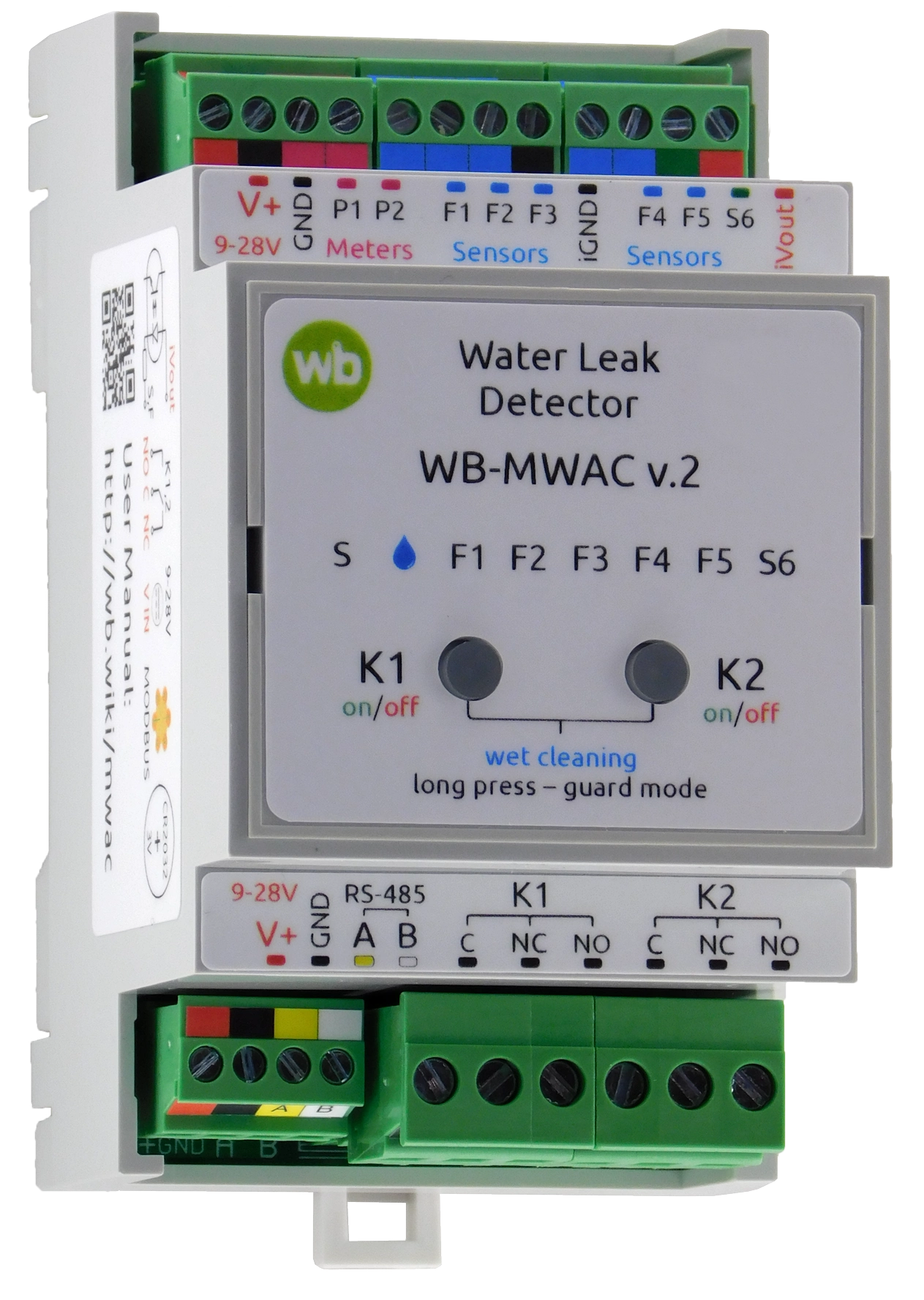
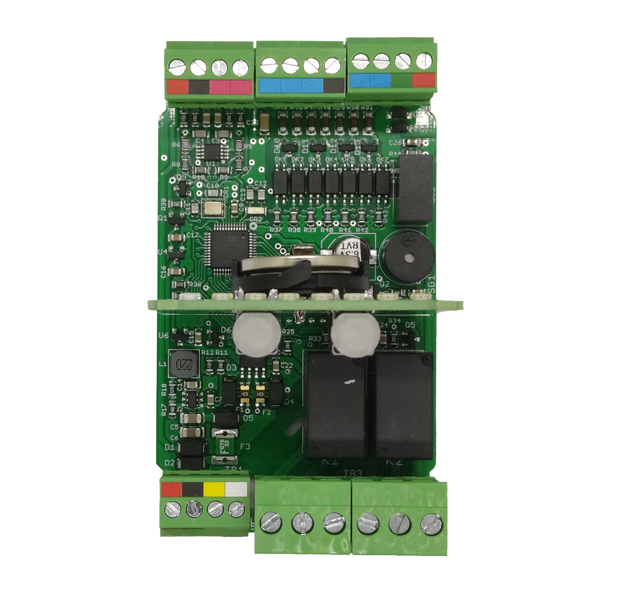
WB-MWAC v.2 detects water leaks, automatically controls shut-off valve actuators, meters water consumption and counts pulses from water meters. A separate nonvolatile counter module continues counting on its battery when external power is absent.
Default settings monitor up to five zones; the sixth input connects a Wet cleaning mode button. Input actions can be customized to monitor six zones or add buttons for alarm reset, Wet cleaning mode or relay control.
Two changeover dry-contact relay outputs control shut-off valves and allow actuators with any control voltage within the relay contact ratings.
Two front-panel buttons, K1 and K2, control outputs, Wet cleaning mode, alarm reset and buzzer muting.
The module supports wired leak sensors only; see the Leak sensors section for tested models.
Differences from the previous version
Main differences from WB-MWAC v.1:
- two illuminated front-panel buttons for relay control, buzzer muting and alarm reset;
- six input-state indicators;
- five inputs configured for leak sensors and one for Wet cleaning by default;
- Wet cleaning mode ignores leak sensor activation for 20 minutes by default; the duration is configurable;
- valve anti-seizing function;
- P1 and P2 provide an additional cubic-metre counter with configurable initial value and pulse weight;
- iVout overload monitoring;
- support for Larnitech leak sensors with health monitoring;
- no input frequency measurement;
- larger CR2032 battery for pulse counting without external power, with battery state checked at module restart.
Technical specifications
| Parameter | Value |
|---|---|
| Power supply | |
| Supply voltage | 9–28 VDC |
| Power consumption |
|
| Pulse-counting operation without external power, using the internal CR2032 battery | up to 12 months |
| Outputs | |
| Number of outputs | 2 |
| Output type | Mechanical relay contacts |
| Relay contact configuration | SPDT |
| Maximum switching voltage, AC | 250 V |
| Maximum switching voltage, DC | 30 V |
| Maximum switched current per channel | 3 A |
| Maximum switching current per channel, DC | 3 A at 30 V (resistive load) |
| Contact resistance | < 100 mΩ |
| Isolation voltage between controller and output | 1500 V RMS |
| Operating life | 100,000 operations at 3 A / 230 VAC |
| Relay model | Hongfa HF32FA/005-Z2 |
| Inputs | |
| Number of universal control inputs | 6: F1-F5, S6 |
| Input type | Digital inputs dry contact, group isolation
Their functions are described under Terminal assignments |
| Pulse frequency and duration at isolated inputs | Up to 9 Hz (T > 50 ms) by default;
up to 1 kHz with a shorter debounce interval |
| Counter inputs | |
| Number of counter inputs | 2: P1-P2 |
| Input type | Digital inputs dry contact, non-isolated
|
| Maximum frequency | 10 Hz |
| Indicators | |
| LED and audible | See Indicators |
| Control | |
| Control interface | RS-485 |
| Interface isolation | Non-isolated |
| Communication protocol | Modbus RTU; software-configurable address; factory settings are printed on the label |
| RS-485 interface parameters | Software-configurable; defaults:
baud rate — 9600 bit/s; data — 8 bits; parity — none (N); stop bits — 2 |
| Ready after power-on | ~2 s |
| Operating conditions | |
| Ambient air temperature | 0 to +60 °C |
| Relative humidity | Up to 95%, non-condensing |
| Climatic classification under GOST 15150-69 | O2.1* |
| Warranty | 2 years |
| Service life | 8 years |
| Terminal blocks and wire cross-sections | |
| Recommended wire cross-section with insulated wire-end ferrules | control inputs: 0.35–1 mm2 — single ferrule; 0.35–0.5 mm2 — twin ferrule,
power inputs: up to 2.5 mm2 — single ferrule; up to 1.5 mm2 — twin ferrule |
| Standard ferrule sleeve length | 8 mm |
| Screw tightening torque | control inputs: 0.2 N·m,
power outputs: 0.5 N·m |
| Dimensions | |
| Width, DIN modules | 3 |
| Overall dimensions (L × W × H) | 53 × 90 × 58 mm |
| Weight (including box) | 140 g |
Operating principle
The module functions and algorithms below can partly be customized in the settings.
Indicators
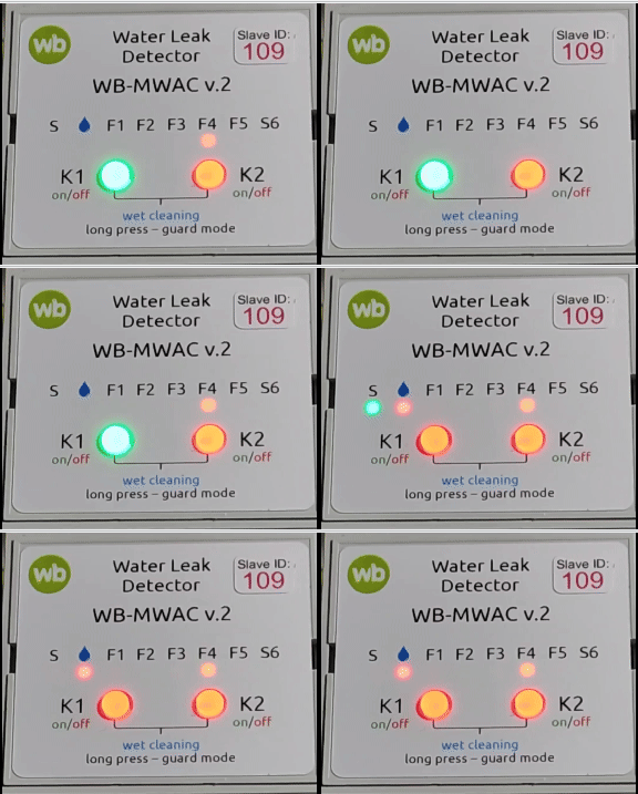
Indicators show module status without a controller connection. Their behaviour is not configurable.
- S (green) — status indicator:
- flashes during the first two seconds after power-on — bootloader mode;
- steady — standalone operation without RS-485 communication;
- flashes during RS-485 polling.
- K1, K2 — button indicators:
- green — relay energized, valve open;
- red — relay de-energized, valve closed.
 (orange) — Leak mode indicator; lights when leak sensors activate.
- F1…F5, S6 (orange) — input indicators:
- in Leak mode, steady while the corresponding sensor is closed; flashes after it dries to identify the leak location. Goes out when Leak mode ends;
- in Wet cleaning mode, flashes; an active input flashes in the opposite phase to inactive inputs.
- buzzer:
- in Leak mode, sounds; mute with a short K1/K2 press;
- in Wet cleaning mode, off;
- can also be controlled by configured input actions, the web interface or a register.
| Module mode | |
F1…S6 indicators | Buzzer |
|---|---|---|---|
| Armed | OFF | OFF | OFF |
| Leak | ON | Shows the activated input | ON; mute with a short K1/K2 press, or configure control from inputs, the web interface or a register. |
| Wet cleaning | OFF | Flashing; an active input flashes in the opposite phase | OFF |
Inputs
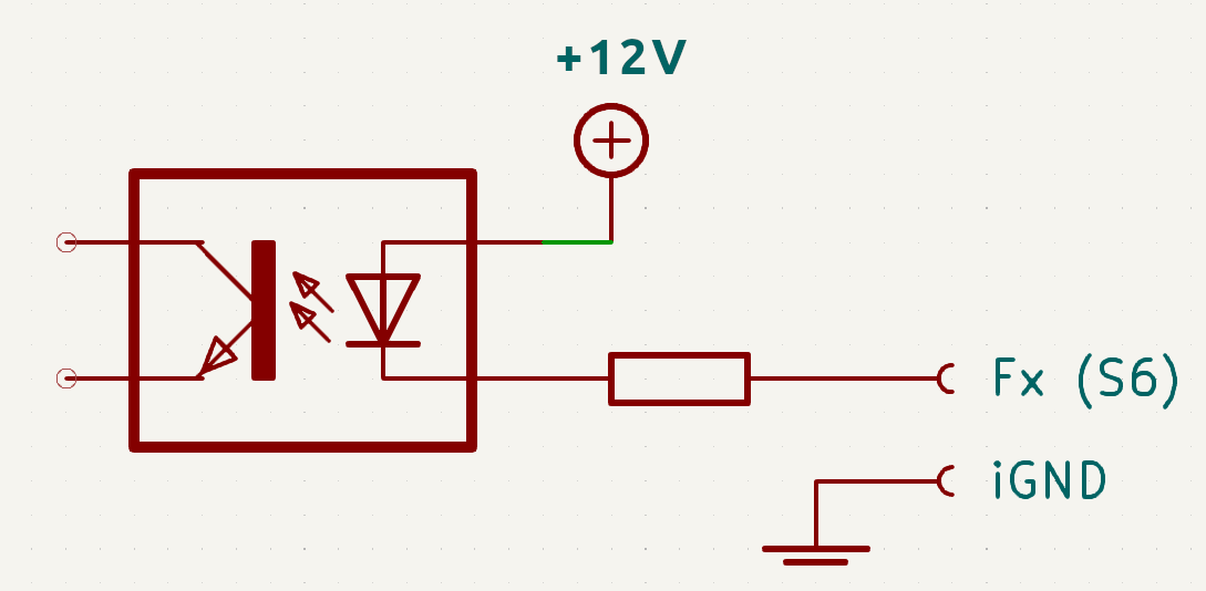
The module has two input types:
- six isolated universal inputs, F1…F5 and S6, for leak sensors or buttons;
- two non-isolated counter inputs, P1 and P2, for pulse meters; these count independently of external power.
Universal inputs are configurable. Defaults:
- F1…F5: Leak sensor mode, Normally open (NO) sensor type. Activation of any sensor opens the relay NO contact.
- S6: Digital input or pushbutton mode. A short press enables Wet cleaning; a long press disables it.
In Digital input or pushbutton mode, each universal input detects short, long, double and short-then-long presses. For latching switches, enable edge-based control and configure actions for input closure and opening.
Input states and closure/press counters are readable over Modbus. To use press counters with a Wiren Board controller, enable their polling in
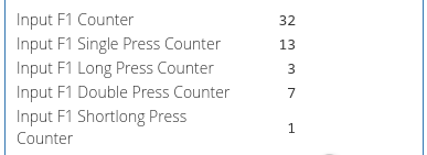
Contact-closure and press counters
Closures of universal inputs to iGND are counted by Input X counter (Input Counter). Available in every input mode, these count pulses and dry-contact activations.
In Digital input or pushbutton mode, additional press counters are available:
- Single Press Counter,
- Long Press Counter,
- Double Press Counter,
- Shortlong Press Counter.
These count recognized press types rather than contact closures and are intended for pushbuttons.
Input counter and Single press counter serve similar purposes but process contact closures differently:
- Input counter increments as soon as the input closure is accepted after the configured debounce time;
- Single press counter increments when a short press has been detected without a second press. The response time is the short-press duration plus the second press waiting time.
Therefore, when using the Single press counter for digital signals, you may need to reduce the second-press waiting time. For pulses and reed-switch activations, use Input counter; for push-buttons, use the press counters.
Universal input counters are stored in the microcontroller RAM and reset when power is removed.
WB-MWAC also has dedicated P1 counter (P1 Counter) and P2 counter (P2 Counter) for water-meter pulses. Their values are stored in nonvolatile memory.
Useful resources:
Outputs
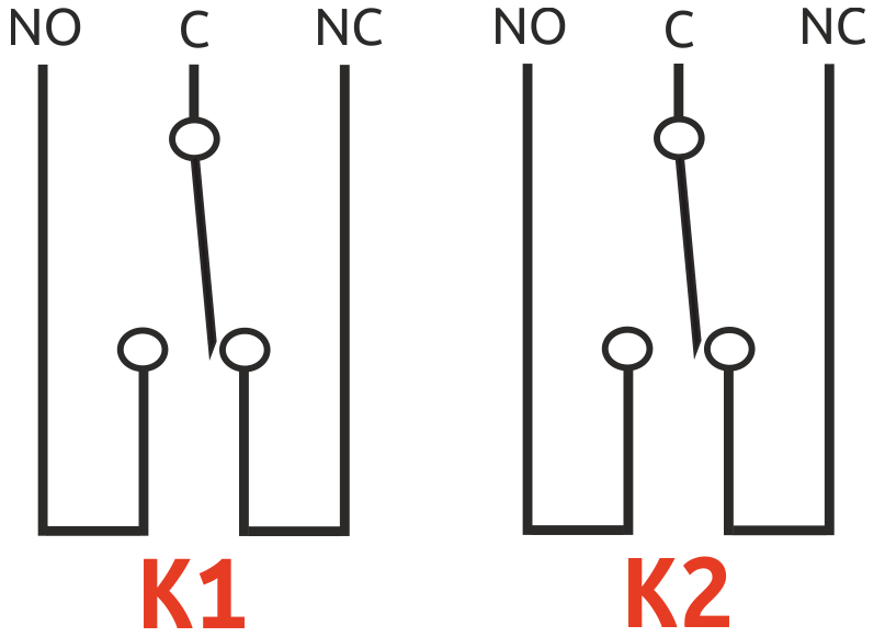
The module has two changeover dry-contact relay outputs for shut-off valve actuators. By default, relay state is not retained, so both relays are off after power cycling. This can be changed in the settings.
By default, the relay NO contacts open when a leak sensor activates.
In Leak sensor mode, each relay action is configurable independently, allowing one module to shut off two separate water zones. The Leak indicator and buzzer are shared by both zones.
Local control
Local controls include front-panel K1/K2 buttons and input S6, configured as a momentary button by default. Front-panel button behaviour is fixed; S6 and F1…F5 behaviour is configurable.
| Module mode | K1 short press | K2 short press | (K1+K2) or S6 short press | (K1+K2) or S6 long press |
|---|---|---|---|---|
| Armed | OPEN/CLOSE valve K1 | OPEN/CLOSE valve K2 | Wet cleaning | No action |
| Leak | mutes the buzzer | mutes the buzzer | Wet cleaning | Armed |
| Wet cleaning | OPEN/CLOSE valve K1 | OPEN/CLOSE valve K2 | No action | Armed |
Leak alarm mode
The module monitors leak sensors. When one activates, it:
- de-energizes the relays to close the valves and remembers their previous states;
- activates the Leak indicator and buzzer;
- identifies the activated sensor with its orange indicator.
Leak indicator, relay and input states are also transmitted over Modbus for the automation system.
Available since firmware 1.27.2 An iVout sensor-power overload is also treated as a leak because unpowered sensors cannot detect water, for example when a cable is crushed or short-circuited. If the overload lasts longer than 1 second, the module performs the actions configured for all inputs in Leak sensor mode: by default it closes the valves and turns on the buzzer and Leak indicator.
Operating details:
- if the overload remains after the alarm is reset, the alarm resumes after 1 second;
- brief overloads while power is applied or sensors are connected are ignored;
- in Wet cleaning mode, an overload, like a triggered sensor, causes no action until cleaning ends;
- the overload flag is reported over Modbus in discrete register 15 (the wb-mqtt-serial template channel is iVout Overloaded and is disabled by default).
With the default settings, use the front-panel buttons or input S6 to enter Wet cleaning or Guard mode. Either action turns off the Leak indicator and restores the valves to their pre-alarm state; this restoration can be disabled in the settings.
Wet cleaning mode
Floor-mounted leak sensors can trigger during wet cleaning and shut off water. Enable Wet cleaning mode to prevent this.
On activation, the module beeps and input indicators flash. For 20 minutes it displays sensor states but ignores their programmed actions. It then returns to Armed mode. If a sensor remains wet, default leak protection closes the valves and activates the Leak indicator and buzzer.
With default settings, enable this mode from the front-panel buttons or S6. Its duration is configurable.
Valve anti-seize protection
Available from firmware 1.24.0 The anti-seizing function periodically closes and opens valves to prevent sticking during long idle periods. Timing starts from the last opening and resets when the valve closes. Configure cycle duration in seconds, interval in days and start hour.
A user command, safe-mode transition or leak sensor activation can interrupt the cycle.
If interrupted, or if the device is in Leak mode, safe mode, without power, or has recorded water use during the last hour when that restriction is enabled, the cycle is postponed by one day.
Button indicators flash green while the function runs.
For details, see Configuration.
Terminal assignments
| Label | Description | Purpose |
|---|---|---|
| Connecting sensors, buttons and meters | ||
| P1, P2 | Dry-contact inputs, non-isolated, nonvolatile counting | For pulse meters. The internal battery maintains counting even without external WB-MWAC v.2 power |
| F1...F5, S6 | Isolated dry-contact inputs |
Connect buttons and leak sensors. By default, F1…F5 are configured for normally open leak sensors and S6 for a pushbutton. Multiple leak sensors may be connected in parallel to one input. Four input modes are available; see Input modes. |
| iGND | Isolated ground for F1…F5 and S6 | Connect buttons and leak sensors between Fx (S6) and iGND. |
| iVout | Isolated 12 V supply output for three-wire leak sensors | Leak sensor power |
| Valve control | ||
| Kx: C, NO, NC | Dry relay contacts:
|
Connecting valves and other loads |
| Lower terminals: module supply and controller communication | ||
| V+ | 9–28 VDC | Main module supply |
| GND | GND | |
| A, B | RS-485 | RS-485 connection. Either GND can be used; they are internally connected |
| Upper terminals: backup module supply | ||
| V+ | 9–28 VDC | The backup supply input can serve as the main supply.
V+ inputs are diode-coupled, so different supply voltages can be used; the higher-voltage source powers the module. Main and backup GND terminals are internally connected |
| GND | GND | |
Installation
Before installation, remove the paper strip protruding from under the cover to connect the pulse-counter battery.
WB-MWAC mounts on a standard 35 mm DIN rail and occupies three DIN modules.
The V+ GND A B terminal block, with a 3.5 mm pitch, connects the power supply and RS-485 communication bus. Correct bus wiring is essential for reliable communication; see RS-485 bus wiring and connection.
If devices on the RS-485 bus use different power supplies, their GND terminals must be interconnected. See Grounding Wiren Board devices and connecting GND and iGND.
Do not exceed the recommended 3 A switching current at the relay contacts.
Digital inputs activate when connected to iGND. The current is low (~2 mA), so any suitable button or switch type can be used. Cable length and cross-section are not critical for contact detection. To reduce interference from nearby power wiring, use twisted pair and connect iGND to the second conductor of the pair. More about connecting iGND/GND terminals.
Operate the module under the recommended environmental conditions.
Installation example
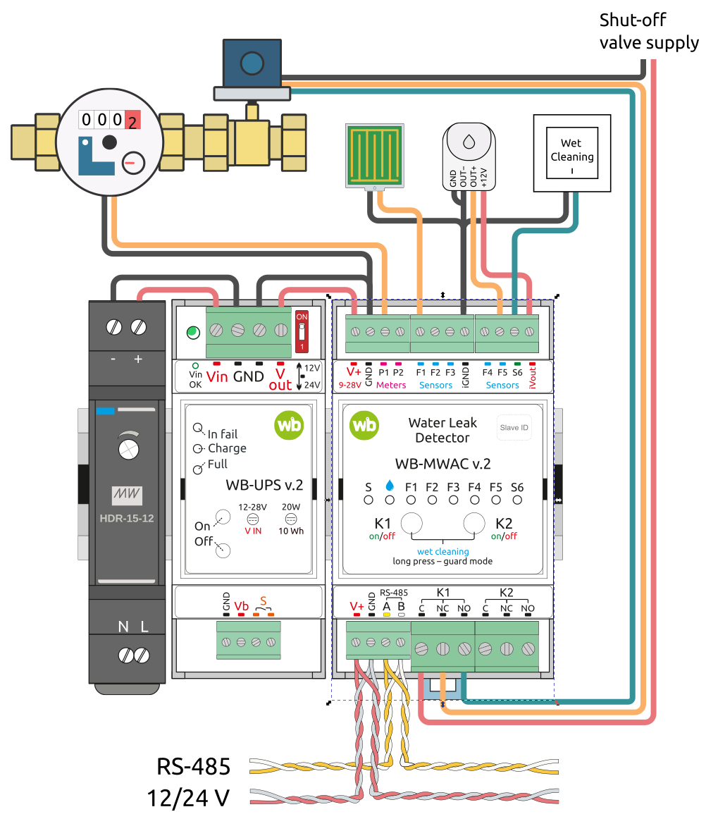
The diagram shows an installation using default settings:
- counter input P1 connects to a water-meter output; counting continues regardless of main or backup power;
- input S6 connects to a switch for enabling/disabling Wet cleaning mode;
- inputs F1 and F5 read two leak sensors: a passive two-wire sensor and an active four-wire sensor;
- relay contacts K1 connect to a motorized ball valve. Follow the valve manufacturer's wiring instructions.
A second water meter, another valve and additional sensors can be connected similarly.
When any leak sensor activates, the module sounds the buzzer, lights the speaker indicator and closes the valve connected to relay K1 . A short K1+K2 or S6 press then selects Wet cleaning; a long K1+K2 or S6 press selects Armed mode.
WB-MWAC backup power is supplied by WB-UPS v.2 connected to a separate 12 V supply. During a brief main-supply outage, WB-MWAC continues monitoring and can sound the alarm. If the valve also has backup power, the module can shut off water during the fault.
F1–F5/S6 functions and alarm behaviour can be changed in settings.
Shut-off valve actuators
Changeover dry-contact relays accommodate many valve actuators: one- or two-control-wire types, powered by 12/24 VDC or 230 VAC, within contact ratings.
The diagrams below show typical actuator connections; always check the documentation for your actuator.
- Actuator connection examples
-
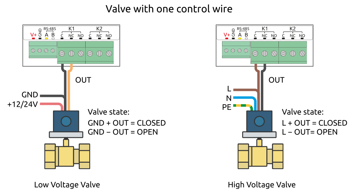 Actuators with one control wire
-
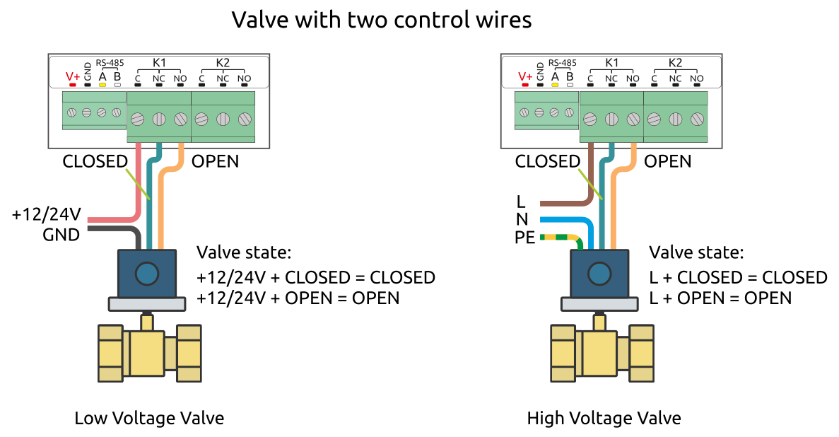 Actuators with two control wires
Water leak sensors
WB-MWAC supports wired passive, active and Larnitech leak sensors. Several ordinary leak sensors can be connected in parallel to each F1…F5/S6 input, increasing coverage within a zone without increasing the number of zones.
Choose Normally open (NO) or Normally closed (NC) sensor type.
Passive sensors
Passive leak sensors need no supply and connect with two wires between F1…F5/S6 and iGND.
Tested models:
- Rielta DZ-12V
- TEKO Astra-361
- H2O Kontakt, version 1
- Vega DP-1
- Gidrolock WSP
- Politech DP-1
Active sensors
Active leak sensors require power: signal to F1…F5/S6, negative to iGND, positive to iVout. For four-wire sensors, join supply negative and signal negative at iGND.
iVout supplies approximately 12 V, up to 50 mA. Check each sensor's specified consumption and the combined load before connecting.
Tested models:
- EctoStroy (ec01006)
- Neptun SW007
- H2O Kontakt, version 2
- Gidrolock WSU (OUT2, black wire)
- Gidrolock WSS
- Larhitech EW-WL.B; specified current: 20 mA
- iRidi FS-WT-OCS-BIF flush-mounted, with health monitoring. Purchasing requires signing in to the vendor website.
- Equation BASE.
For Larnitech sensors, only digital operation and health monitoring are supported, with one sensor per module input.
Sensors with health monitoring
Connect one three-wire sensor per input: common, signal and supply. When dry, these sensors emit short pulses every few seconds, allowing the module to detect presence and operation. During a leak they maintain an active output until dry. Configure them like other sensors, then enable Input xx Sensor Presence polling to monitor health.
- Sensor wiring and configuration example
-
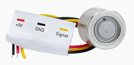 iRidi sensor FS-WT-OCS-BIF
-
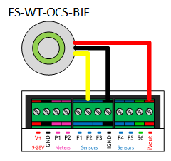 FS-WT-OCS-BIF connection
-
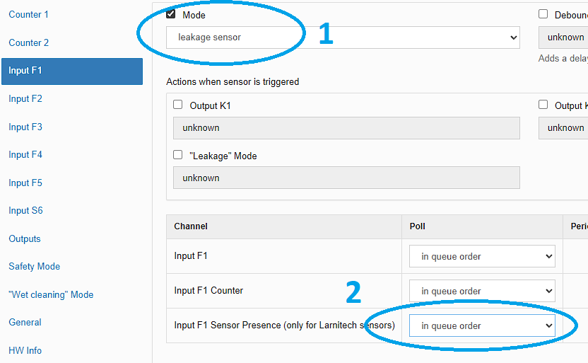 Sensor settings
Larnitech sensor EW-WL.B connects similarly; the signal lead on EW-WL.B is white.
For sensors with health monitoring, select Normally open (NO) as the sensor type for that input.
Safety requirements for leak sensor installation
Leak sensors are installed in high-risk wet locations such as bathrooms and shower rooms. The source cites GOST 50571.7.701-2013; spaces under baths or shower enclosures containing sensors are classified as Zone 1.
Zone 1 requires additional protective measures: SELV at no more than 25 VAC or 60 VDC, plus supplementary equipotential bonding. Sensors must be directly connected.
The galvanically isolated WB-MWAC inputs and iVout meet the source's extra-low-voltage supply requirements and form SELV circuits. Therefore, when connecting leak sensors, iGND must not connect to any other circuit, including the equipotential bonding system. Route these wires separately from other circuits or within an additional sheath or enclosure such as PVC conduit, cable duct, plastic pipe or steel pipe.
The MWAC supply also has requirements:
- power-supply galvanic isolation must be rated for a nominal 4000 V impulse withstand voltage;
- the supply must power only one or more MWAC modules.
Wiren Board controller web interface
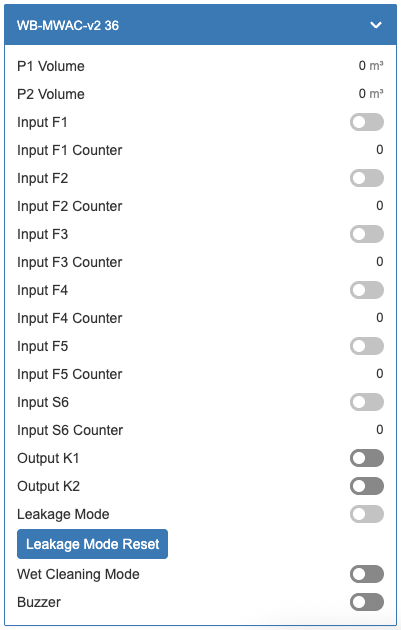
Selecting a template
To display the device on the Devices tab of the Wiren Board controller web interface, add it automatically by scanning for Wiren Board devices on RS-485 or manually by selecting the template WB-MWAC v.2.
Controlling the device and viewing values
The web interface allows you to control device outputs and view readings. To change the displayed channels, edit the device configuration in the wb-mqtt-serial driver settings.
Configuration
Configuration methods
- Set the parameters in the Wiren Board controller web interface under Settings → Configs → Serial devices driver configuration. If these items are unavailable, check your access level.
- Write settings to the Modbus registers of the module from the controller console using the utility modbus-utils-rpc or modbus_client.
- Without a Wiren Board controller, use the Wiren Board device web configurator or other software; see Using Wiren Board Modbus devices without a controller. You will need a computer with an interface converter: USB-RS485.
Our devices are continually improved. If settings described in this manual are missing, update the device firmware and controller software.
Input configuration
Debouncing
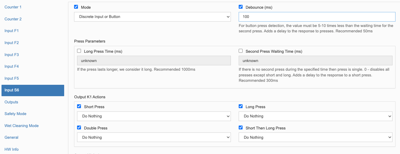
For any of the six F1…F5/S6 inputs, configure debounce filtering using Debounce Time (ms). Range: 0–250 ms; default: 50 ms.
Input modes
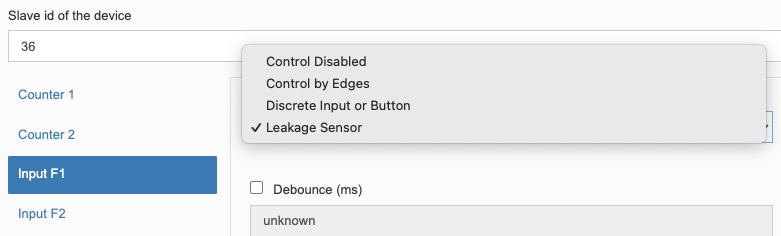
Each of F1…F5 and S6 supports:
- Control disabled — no local input action, but input state and closure counter remain available over Modbus.
- Leak sensor — dedicated leak sensor mode.
- Digital input or pushbutton — signal-edge processing and button press-type recognition.
- Edge-based control — assign actions to input closure/opening, useful for latching switches or inverted-logic sensors.
Leak sensor
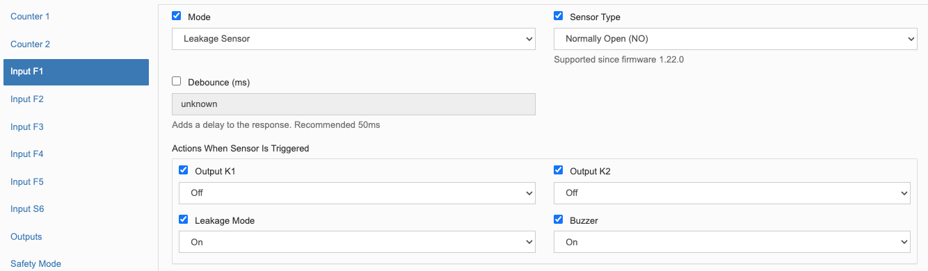
For Leak sensor mode, configure relay actions and Leak mode independently for each relay.
Buzzer actions and sensor type, NO or NC, are also configurable.
Control from switches
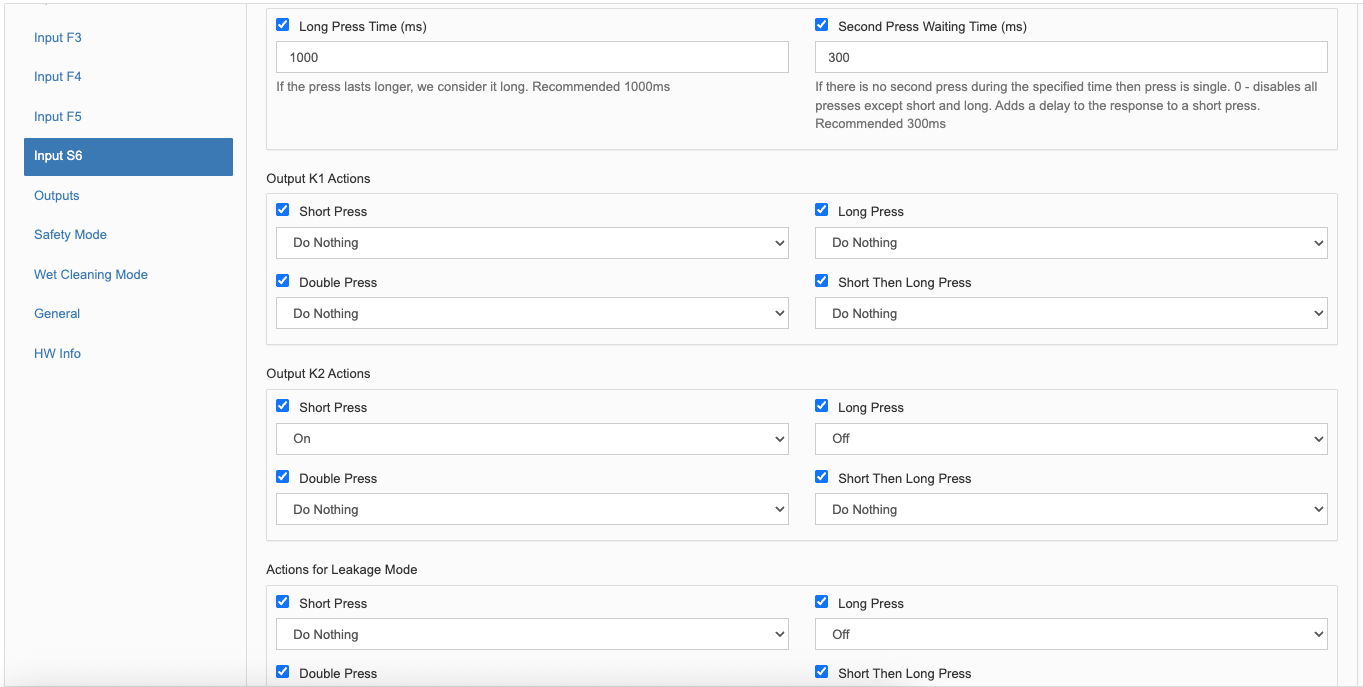
When enabling Digital input or pushbutton you can assign actions to each of four press types and to input closure/opening, allowing flexible module behaviour.
Available settings:
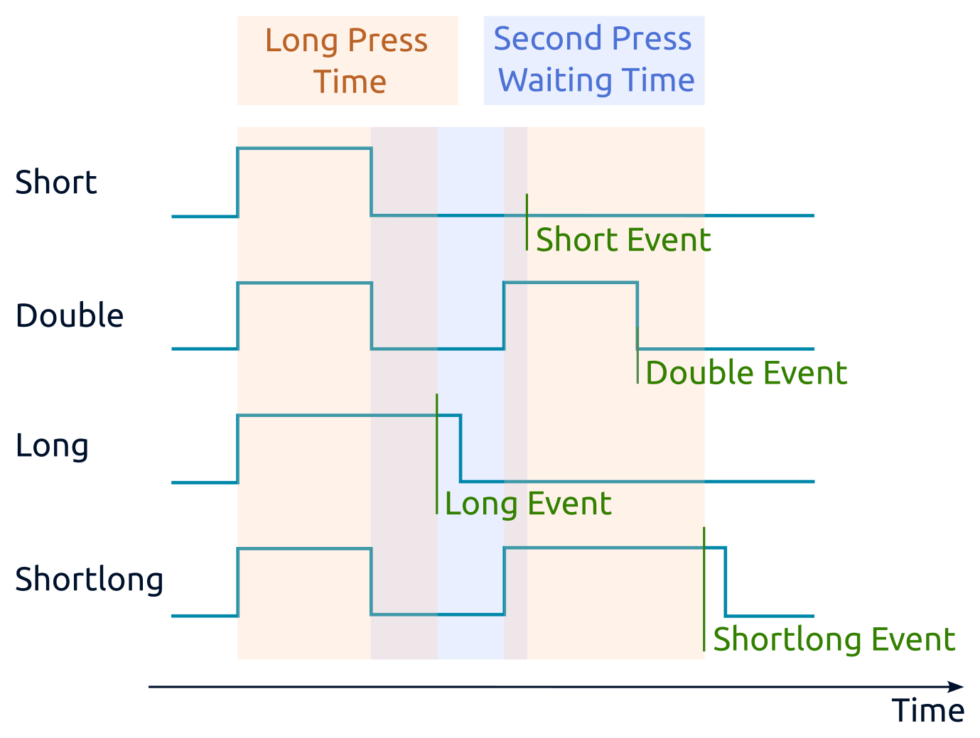
- Long Press Time (ms) — distinguishes long and short presses. A press lasting longer than this value is long; otherwise it is short.
- Second Press Waiting Time (ms) — opens a time window after a short press ends. A second press within this window is treated as a double press; otherwise the first press is treated as a single press.
- Debounce Time (ms) — the input signal must remain stable for this duration before it is accepted and processed by the press-recognition algorithm. For press recognition, set it to one fifth to one tenth of the second press waiting time.
- Polling interval for each counter — leave this at the default value; the driver manages polling automatically.
Double-press detection delays short-press detection. For example, with the default 300 ms setting, the short-press event occurs 300 ms after the button is released. If double presses and short-then-long presses are not required, set Second Press Waiting Time (ms) to 0 ms. The short-press event will then occur immediately after button release.
Press recognition takes place after debouncing. With Debounce time set to the default 50 ms, presses shorter than 50 ms are ignored. Button release is also registered 50 ms after physical release. Choose the debounce time for the particular button to minimise latency while preventing false events, such as a double press being detected instead of a single press.
Edge-based control
Description under development in the source.
Safety Mode
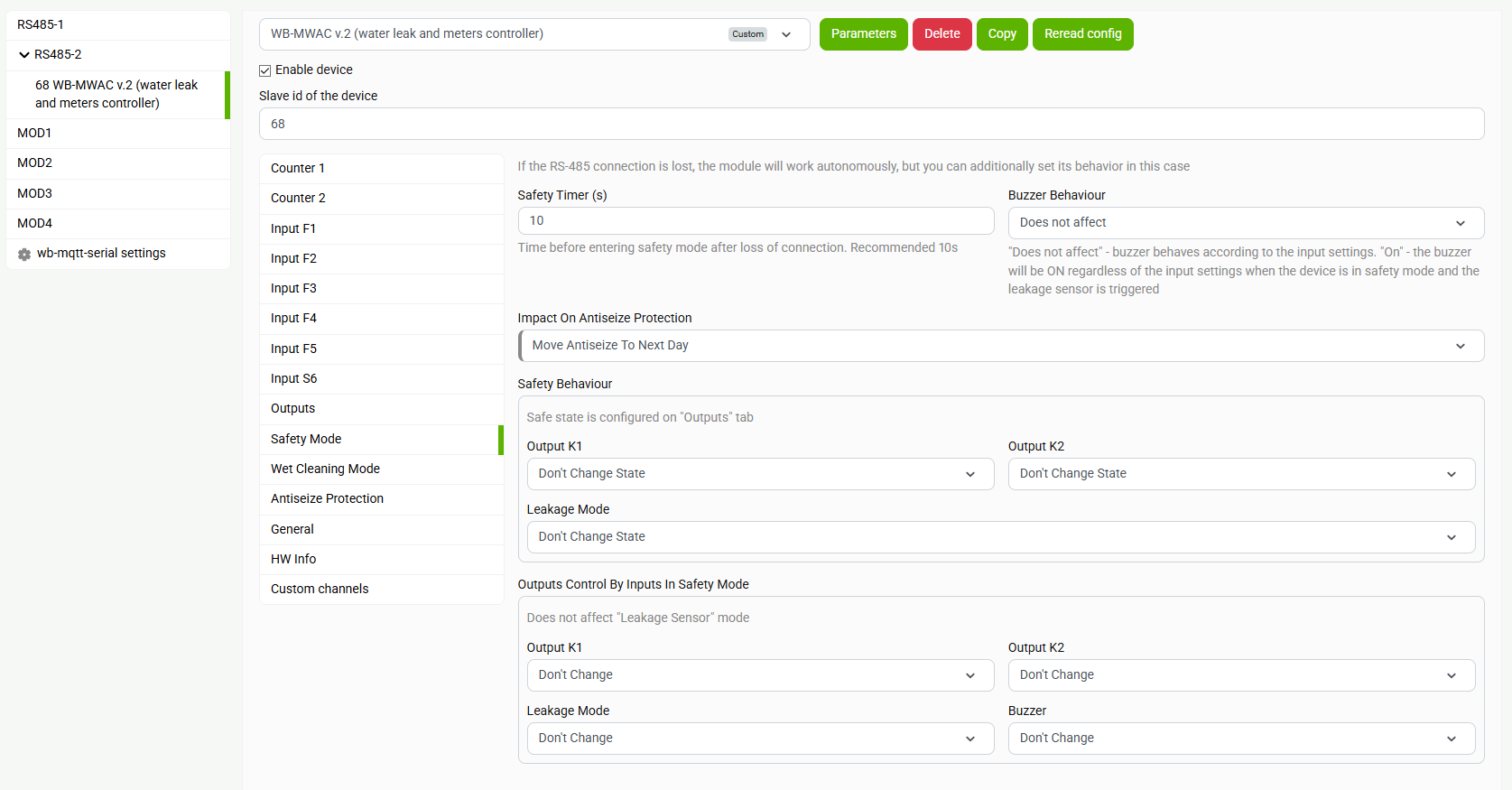
On loss of RS-485 communication, leak protection continues autonomously according to the configured settings.
Safe mode can additionally alter normal behaviour. Its timer restarts after each successfully processed Modbus packet. If communication does not return before the configured timeout, the module enters safe mode. Default timeout: 10 seconds.
Output behaviour in safe mode can be:
- Do nothing;
- Set the output to a selected safe state, on or off.
Input response in Digital input or pushbutton mode is also configurable:
- Do not block — configured input control remains available.
- Block in safe mode — inputs cannot control the module.
- Allow only in safe mode — configured input control is available only in safe mode.
Configure buzzer behaviour for leak activation during safe mode. This overrides the sensor's normal Buzzer action setting. Buzzer control from Digital input or pushbutton inputs can also be configured as described above.
For Leak sensor inputs, safe-mode input-control restrictions are ignored: leak sensor response always remains active.
Output states at power-up
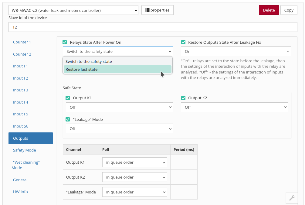
Use Relays State After Power On to choose startup behaviour:
- Set output to safe state — select each output state in Fail-safe output state.
- Restore last state — relay NO contacts that were closed before power loss close again after power returns.
Wet cleaning
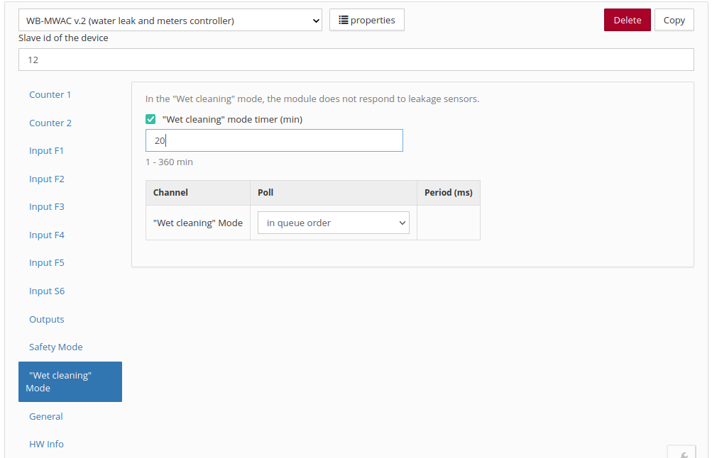
Wet cleaning duration ranges from 1 to 360 minutes; default: 20 minutes.
See Operating principle near the beginning of this page for details of Wet cleaning mode.
Valve anti-seize protection
Available from firmware 1.24.0
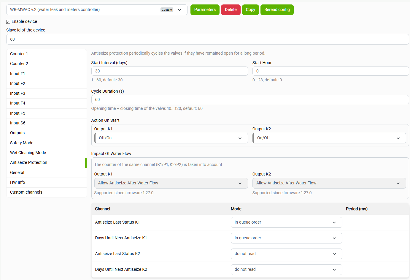
- Impact On Antiseize Protection — allow the function in safe mode or postpone it until the next day.
- Interval (days) — time from the valve's last opening until the next cycle.
- Start hour — hour of day to run the function.
- Cycle duration (s) — opening duration plus closing duration.
- Action at start — disable the function or choose one of two actions:
- off/on — output off means valve closed; timing starts from the last output switch-on;
- on/off — output on means valve closed; timing starts from the last output switch-off.
Available since firmware 1.27.0 Water-use effect on anti-seizing — allow the function despite water use or postpone until the next day if pulses occurred during the last hour. It uses the corresponding meter: P1 for K1 and P2 for K2.
The result is available through two channels per relay. Polling is disabled by default; enable it in the channel table to show them in the web interface:
- K1 anti-seizing status, K2 anti-seizing status — result of the last cycle: completed successfully, in progress (closing/opening), interrupted, or never run.
- Days until K1 anti-seizing, Days until K2 anti-seizing — days until the next run: 0 means today; unset means not yet determined.
Available since firmware 1.27.0 If the start is postponed for one day, K1 anti-seizing status and K2 anti-seizing status also report the reason: safe mode, leak, or water flow.
For details, see Operating principle.
Modbus operation
Wiren Board devices use Modbus RTU. The physical connection uses the RS-485.
interface. All main commands for reading and writing one or multiple registers are supported. See the list in the Modbus protocol description.
The module can be configured:
- in the Wiren Board controller web interface;
- using the Wiren Board device web configurator;
- using third-party software.
Default port settings
| Value default |
Parameter name in the web interface |
Parameter |
|---|---|---|
| 9600 | Baud rate | Baud rate, bit/s |
| 8 | Data bits | Number of data bits |
| None | Parity | Parity |
| 2 | Stop bits | Number of stop bits |
In current firmware, setting Stop bits is optional: the device also operates correctly when its number of stop bits differs from the Modbus master setting.
For a faster response, we recommend increasing the baud rate to 115200 bit/s; see Communication parameter settings
Modbus address
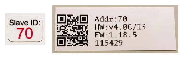
Each device on the bus must have a unique address from 1 to 247. The factory-assigned address is printed on labels on the enclosure (top cover, side or underside). Devices in a production batch are assigned different addresses, so devices in one order will usually have different addresses.
For instructions on finding, changing or resetting the address, see Wiren Board device Modbus address.
Fast Modbus extension
Fast Modbus extends standard Modbus with rapid discovery of Wiren Board devices on RS-485 and event polling.
These features are enabled by a special command from the master, so Wiren Board devices remain compatible with third-party equipment.
Not every register supports event generation. Check the register map: event-capable registers are marked with ⚡. See Fast Modbus.
Register map
Firmware updates and resetting settings
Wiren Board devices support firmware updates over Modbus. This allows bugs to be fixed at the installation site and, where technically possible, new features to be added. Settings stored in the device are retained during a firmware update.
Instructions:
- Firmware update ()
- Resetting settings
- Connection parameter settings
- Modbus address: find, reset or change
- Updating the bootloader
New firmware releases are listed in the firmware changelog.
Software
WB-MWAC water metering module software — description of the embedded software operation.
Known issues
Hardware revisions
Device images and drawings
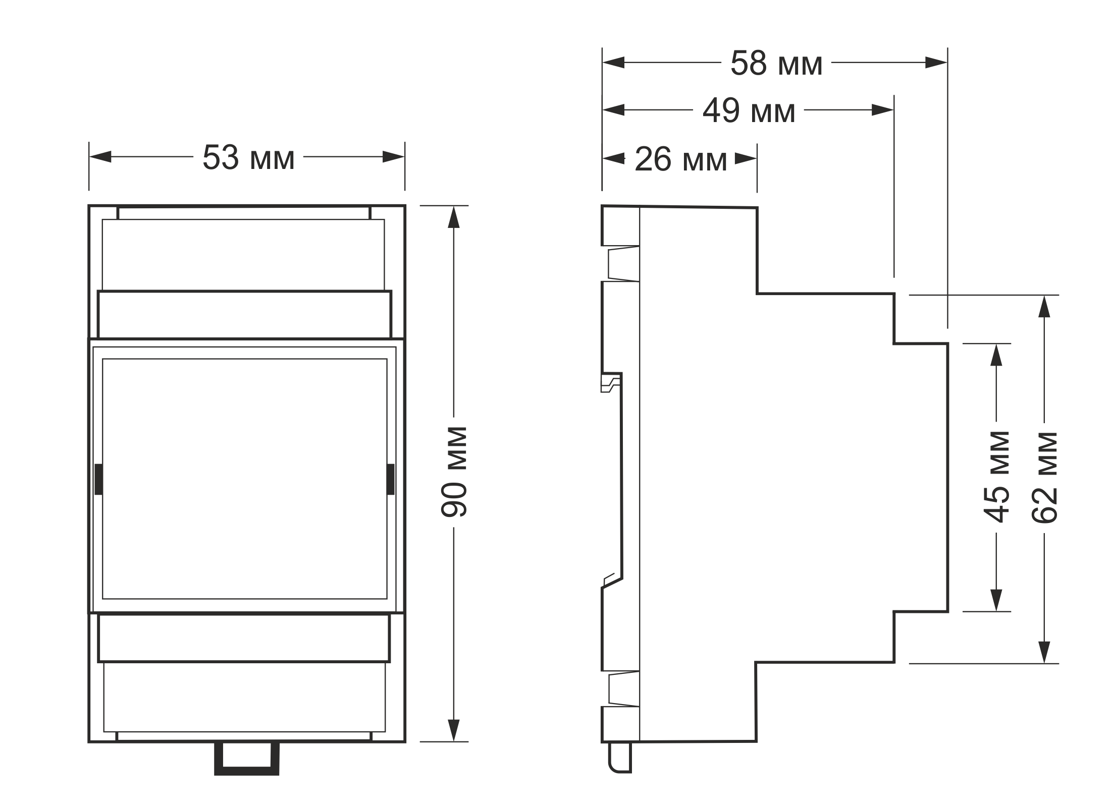
CorelDRAW 2018 (font: Ubuntu): File: WB-Library.cdr.zip
Visio:
- Wiren Board devices: File: WB-Visio-Lib.zip.
- Enclosures, circuit breakers, contactors and other third-party symbols.

Module dimensional drawing (DXF): File: WB-MWAC v.2.dxf.zip
Module dimensional drawing (PDF): File: WB-MWAC v.2.dxf.pdf
AutoCAD Electrical schematic symbol library: File: Wirenboard-AE-base.zip