 Documentation
WB-LED
4-channel LED strip dimmer
Covered order codes (1)
WB-LED
This page describes the new WB-LED device; for the previous version, see WB-MRGBW-D.
This page describes the latest hardware revision with the latest stable firmware. If your device runs older firmware, update it where possible (see Firmware update).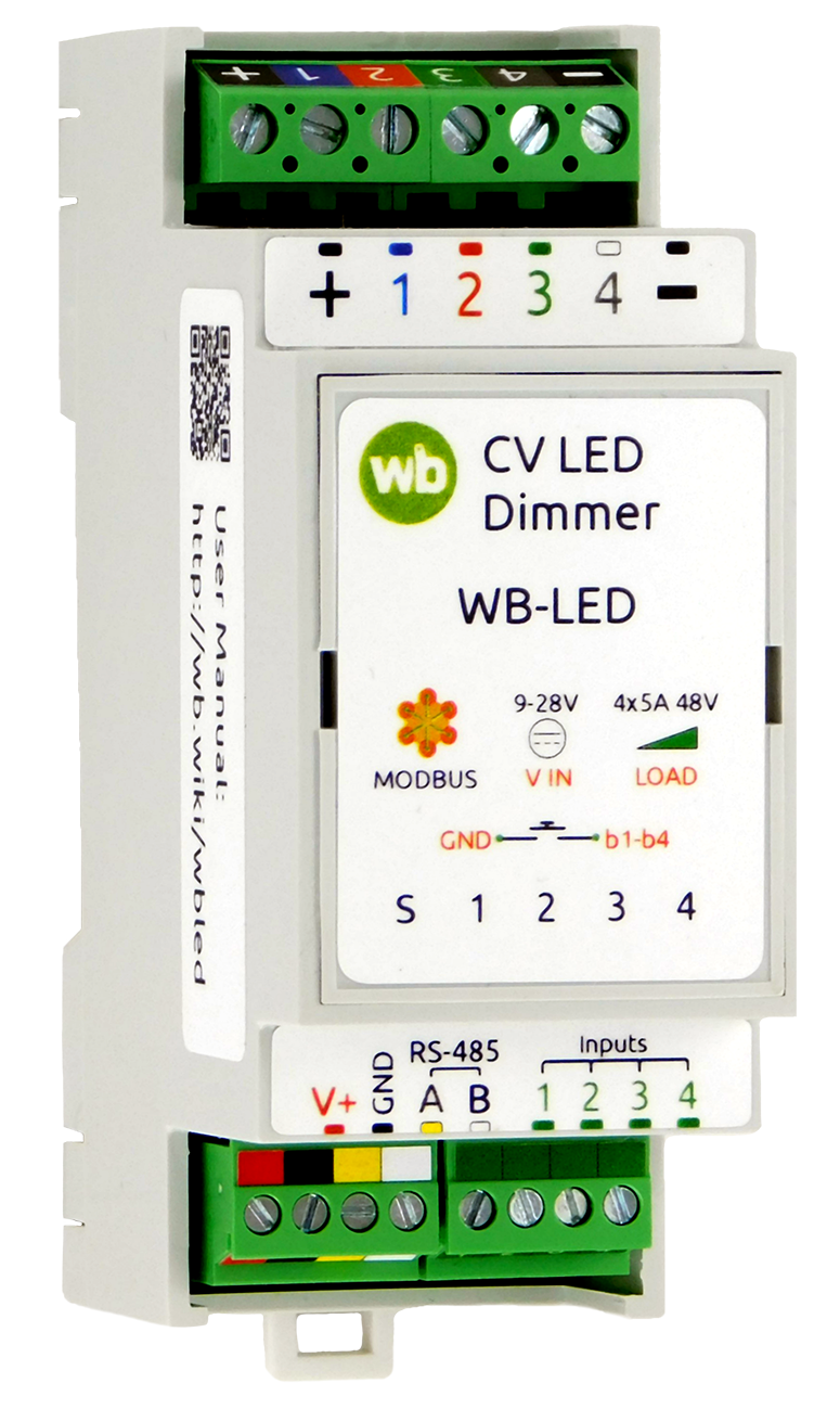
Purpose
WB-LED is a four-channel dimmer for coloured (RGB, RGB+W), tunable-white (CCT) or white (W) LED strips. Configure strip types, PWM frequency and input assignments in the device settings.
The channels can be combined to control one high-power white strip up to 20 A. For more power, use the amplifier WB-AMPLED.
Features:
- 11 operating modes support a wide range of decorative lighting arrangements.
- Universal inputs recognise press types in hardware. Assign an action to each input and press type. For example, a short press on input 1 can toggle an RGB strip, a double press can change its colour, and a long press can change its brightness.
- Adjustable PWM frequency. The default 3 kHz makes flicker imperceptible to the eye and keeps power-supply noise low.
- The dimmer works with Wiren Board and other Modbus RTU controllers. Once configured, it can also operate independently using its local inputs.
Testing established the continuous-duty ratings as a strip voltage up to 48 V and up to 5 A per channel.
Technical specifications
| Parameter | Value |
|---|---|
| Power supply | |
| Supply voltage | 9–28 V DC |
| Power consumption |
0.3 W |
| LED strip control channels | |
| PWM channels for LED strip control | 4 |
| PWM frequency | 3 kHz, adjustable from 100 Hz to 24 kHz |
| Maximum current | 5 A per channel; for higher current, use with WB-AMPLED |
| Maximum voltage | 48 V per channel |
| Inputs | |
| Purpose | Universal inputs with flexible configuration. |
| Input type | Dry contact, without galvanic isolation.
Input voltage approximately 5 V DC; closed-input current approximately 5 mA |
| Permissible voltage | 0 V to +30 V |
| Control | |
| Control interface | RS-485 |
| Interface isolation | Non-isolated |
| Communication protocol | Modbus RTU; software-configurable address; factory settings are printed on the label |
| RS-485 interface parameters | Software-configurable; defaults:
baud rate — 9600 bit/s; data — 8 bits; parity — none (N); stop bits — 2 |
| Ready after power-on | ~2 s |
| Operating conditions | |
| Ambient air temperature | −40 to +80 °C |
| Relative humidity | Up to 95%, non-condensing |
| Climatic classification under GOST 15150-69 | O2.1* |
| Warranty | 2 years |
| Service life | 8 years |
| Terminal blocks and wire cross-sections | |
| Recommended wire cross-section with insulated wire-end ferrules | control inputs: 0.35–1 mm2 — single ferrule; 0.35–0.5 mm2 — twin ferrule,
power inputs: up to 2.5 mm2 — single ferrule; up to 1.5 mm2 — twin ferrule |
| Standard ferrule sleeve length | 8 mm |
| Screw tightening torque | control inputs: 0.2 N·m,
power outputs: 0.5 N·m |
| Dimensions | |
| Width, DIN modules | 2 |
| Overall dimensions (L × W × H) | 36 × 90 × 58 mm |
| Weight (including box) | 85 g |
Operating principle
Brightness is controlled by pulse-width modulation (PWM) of the current. Outputs are described as open-collector outputs: transistors switch each output to ground. PWM resolution is 12 bits, at frequencies up to 24 kHz, avoiding visible flicker and allowing smooth control at low brightness. Change the frequency in the settings if needed.
Channel brightness is set from 0 to 100 and converted to LED output using a logarithmic dimming curve, giving smooth adjustment across the range.
The module has four hardware inputs whose states can be read over Modbus. Assign actions to press types to configure their behaviour. See Input configuration.
Indicators
The module has indicators that show its status without connecting to a controller:
- S (green) — Modbus communication status: lights up when low-voltage power is applied and flashes during polling over RS-485. On devices with events enabled in Fast Modbus ⚡ the indicator flashes more frequently than during sequential polling because events are polled faster. In bootloader mode it flashes once per second; during firmware upload it flashes rapidly.
Four front-panel LEDs indicate the corresponding output states and protection trips. For example, with an RGB strip displaying red, only the red-channel indicator is on. The indications are:
- off — channel inactive;
- on — channel active;
- all LEDs flashing together — overcurrent or overtemperature protection active.
Overcurrent and overtemperature protection
WB-LED includes overcurrent and overtemperature protection.
Overcurrent protection trips if any channel exceeds the maximum permitted load current. All channels switch off and their LEDs flash together four times per second. After 3 seconds, channels gradually restart in sequence beginning with channel 1. If protection trips again, the cycle repeats.
Overtemperature protection starts above a PCB temperature of 70 °C. The dimmer progressively limits maximum output power by reducing PWM duty cycle and switches all outputs off at 80 °C. During thermal power limiting, the channel LEDs flash together four times per second.
Press-type recognition
The module recognises four press types: short; long; double; and short followed by long.
Presses can be processed on the controller, which receives a separate counter for each type over Modbus, or locally in the module to control its outputs.
Press-recognition parameters can be changed in the settings.
Installation
Wiring
Connect the strip/load power supply to the + terminal for correct operation of the dimmer switching stages. Mount the device on a standard 35 mm DIN rail; it occupies two DIN modules.
The V+ GND A B terminal block, with a 3.5 mm pitch, connects the power supply and RS-485 communication bus. Correct bus wiring is essential for reliable communication; see RS-485 bus wiring and connection.
If devices on the RS-485 bus use different power supplies, their GND terminals must be interconnected. See Grounding Wiren Board devices and connecting GND and iGND.
Strip type and wiring depend on the selected mode; see the table Dimmer channel modes.
Output and power terminal assignments:
- 1(B), 2(R), 3(G), 4(W) — control terminals: negative connections of the channels of one or several strips.
- + — positive terminal of the strip power supply. This connection is mandatory. Omitting it with long wiring and high power can destroy the dimmer.
- − — negative strip power supply connection. Use a large-cross-section conductor because it carries the total current of all four channels.
- +V, GND — module logic supply.
- Terminals−(negative) and GND are connected inside the module.
Choose LED-strip wire cross-sections according to installation method, cable length, supply voltage and strip current. Long, thin conductors cause voltage drop, reduced brightness and heating. See Selecting cables for LED strips.
Avoid running cables for separate strips close together, as they may interfere with each other. Reducing PWM frequency can also reduce coupling.
Before connecting strip negative conductors to the dimmer, check strip operation and absence of short circuits by connecting them to the power-supply negative terminal. Connecting shorted wiring to the dimmer can damage it.
Wiring diagrams
LED-strip wiring depends on the selected mode.
The diagrams illustrate the main modes. Other arrangements follow the mode name. For example, in W+W+CCT, connect white strips to terminals 1 (B) and 2 (R), and the CCT strip to 3 (G) and 4 (W), adapting the illustrated CCT+W+W arrangement.
- Connecting LED strips to WB-LED
-
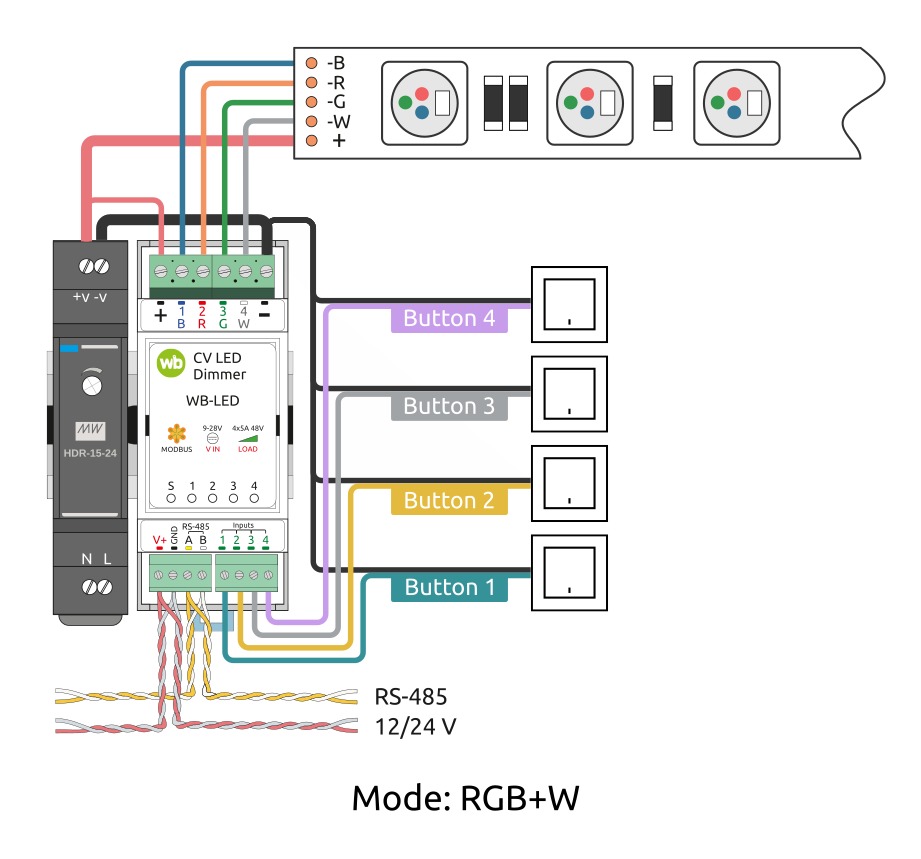 RGB+W strip connection
-
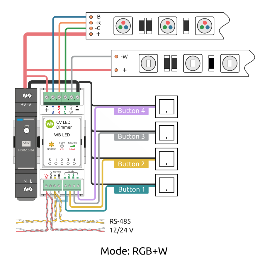 Separate RGB and single-colour strip connection
-
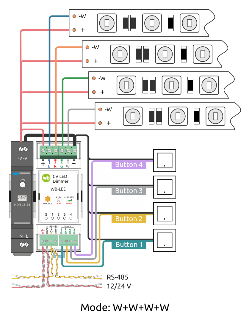 Four single-colour strips
-
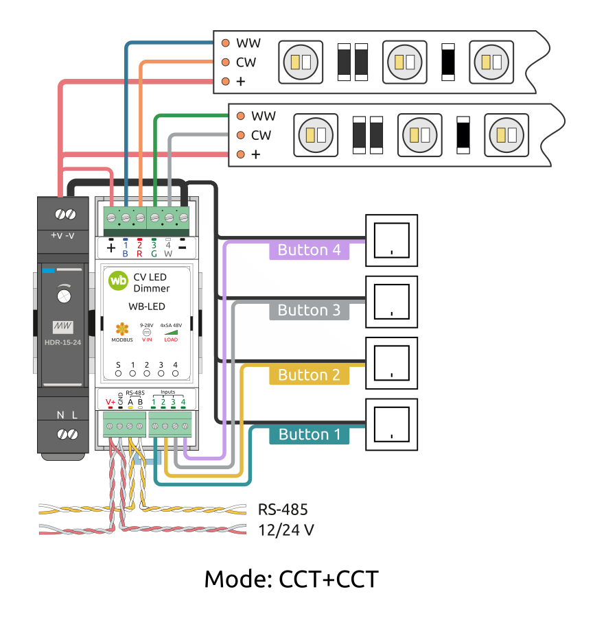 Two CCT strips
-
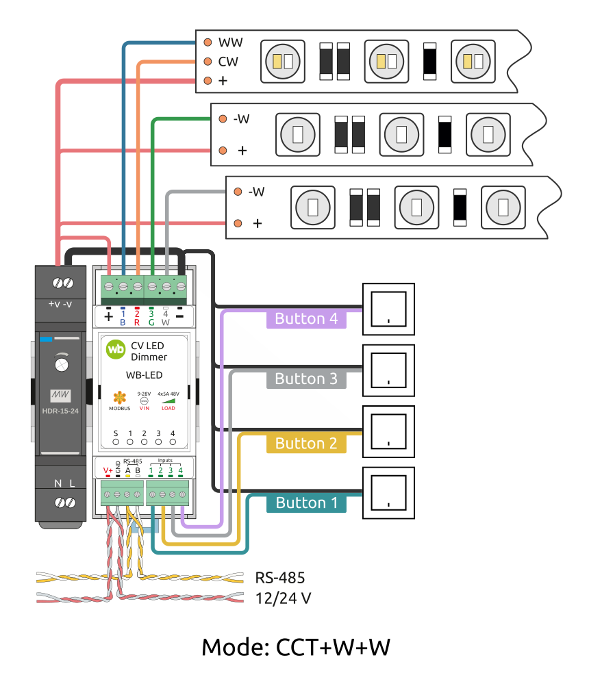 One CCT strip and two single-colour strips
-
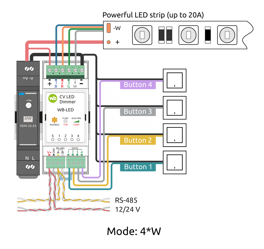 One high-power single-colour strip up to 20 A
Inputs
Inputs recognise press types in hardware, with a separate action assignable to each type. For configuration and available actions, see Input configuration.
Digital inputs activate when connected to terminals−(negative) or GND. The current is low, up to 5 mA, so any suitable button or switch can be used. Cable length and cross-section are not critical for contact detection. To reduce interference from nearby power wiring, use twisted pair and connect the strip supply negative to the second conductor.
Wiren Board controller web interface
Selecting a template
To display the device on the Devices tab of the Wiren Board controller web interface, add it automatically by scanning for Wiren Board devices on RS-485 or manually by selecting the template WB-LED. If the template is missing or the controls differ from those shown here, update the device firmware and controller software.
Controlling the device and viewing values
The web interface allows you to control device outputs and view readings. To change the displayed channels, edit the device configuration in the wb-mqtt-serial driver settings.
Available controls depend on the selected mode.
- Dimmer controls in the controller web interface for different modes
-
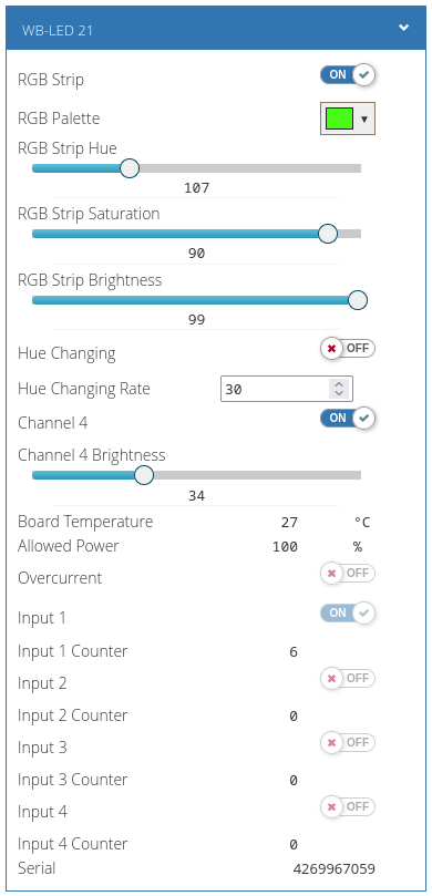 RGB + W
-
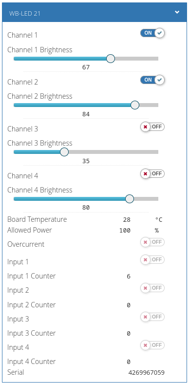 W + W + W + W
-
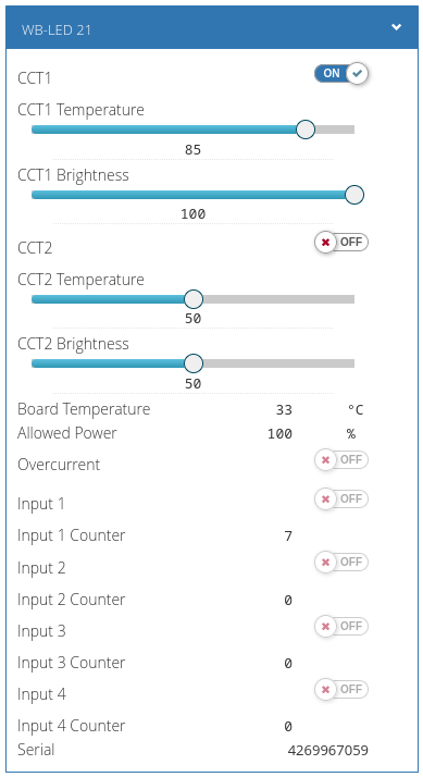 CCT + CCT
-
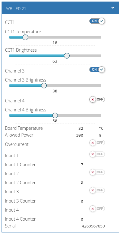 CCT + W + W
-
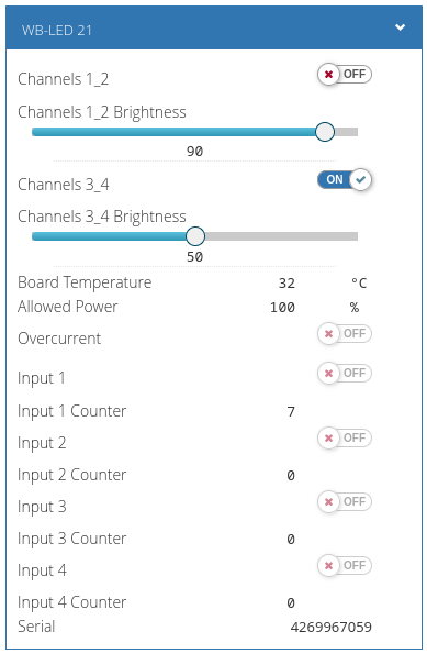 2*W + 2*W
-
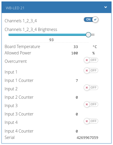 4*W
-
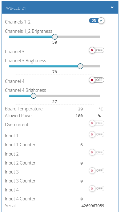 2*W + W + W
-
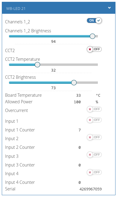 2*W + CCT
-
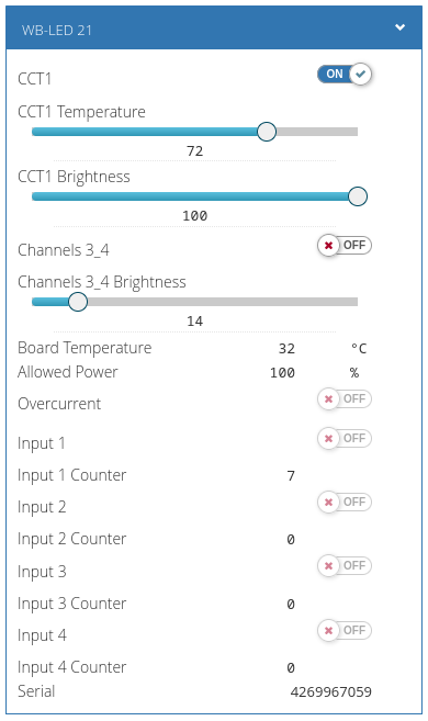 CCT + 2*W
-
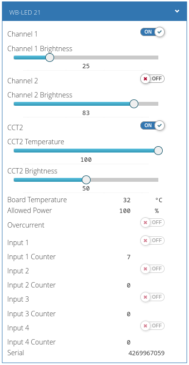 W + W + CCT
-
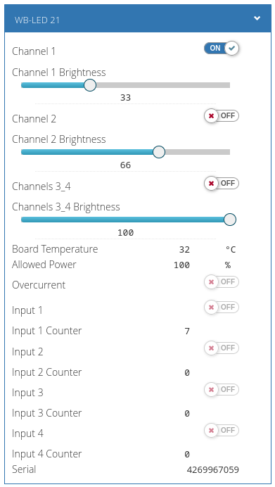 W + W + 2*W
-
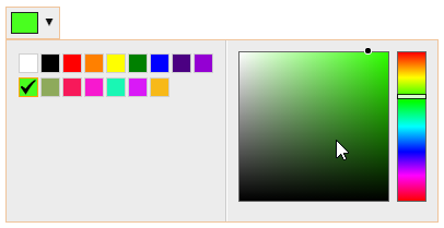 RGB + W: colour selector
Configuration
Configuration methods
- Set the parameters in the Wiren Board controller web interface under Settings → Configs → Serial devices driver configuration. If these items are unavailable, check your access level.
- Write settings to the Modbus registers of the module from the controller console using the utility modbus-utils-rpc or modbus_client.
- Without a Wiren Board controller, use the Wiren Board device web configurator or other software; see Using Wiren Board Modbus devices without a controller. You will need a computer with an interface converter: USB-RS485.
Our devices are continually improved. If settings described in this manual are missing, update the device firmware and controller software.
Modes
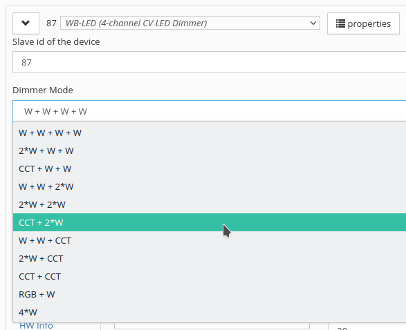
Select the operating mode in the web interface, under the group Dimmer Mode → parameter Mode.
Features:
- White strips (W) provide brightness control from 0 to 100
- Tunable-white strips (CCT) provide colour-temperature control from 0 (warmest) to 100 (coolest), and brightness from 0 to 100
- RGB strips support RGB values from 0 to 255 and HSV control. H, S and V can change smoothly with separate settings.
RGB + W is enabled by default.
For web-interface controls, see Controlling the device and viewing values.
| Mode | Code | Output 1 B |
Output 2 R |
Output 3 G |
Output 4 W |
|---|---|---|---|---|---|
| W + W + W + W | 0 | W1 | W2 | W3 | W4 |
| 2*W + W + W | 1 | W1 + W2 (parallel) | W3 | W4 | |
| CCT + W + W | 2 | CCT1 Warm White (Warm) |
CCT1 Cool White (Cool) |
W3 | W4 |
| W + W + 2*W | 16 | W1 | W2 | W3 + W4 (parallel) | |
| 2*W + 2*W | 17 | W1 + W2 (parallel) | W3 + W4 (parallel) | ||
| CCT + 2*W | 18 | CCT1 Warm White (Warm) |
CCT1 Cool White (Cool) |
W3 + W4 (parallel) | |
| W + W + CCT | 32 | W1 | W2 | CCT2 Warm White (Warm) |
CCT2 Cool White (Cool) |
| 2*W + CCT | 33 | W1 + W2 (parallel) | CCT2 Warm White (Warm) |
CCT2 Cool White (Cool) | |
| CCT + CCT | 34 | CCT1 Warm White (Warm) |
CCT1 Cool White (Cool) |
CCT2 Warm White (Warm) |
CCT2 Cool White (Cool) |
| RGB + W | 256 | B | R | G | W4 |
| 4*W | 512 | W1 + W2 + W3 + W4 (parallel) | |||
| 2*CCT | 768 | CCT1 Warm White (Warm) |
CCT1 Cool White (Cool) |
CCT2 Warm White (Warm) |
CCT2 Cool White (Cool) |
Available from firmware 3.8.0 Mode 2*CCT uses the same physical outputs as CCT + CCT, but controls both strips as one. Shared registers 2018 and 2019 set colour temperature and brightness, so both strips always show the same output. As with modes 2*W and 4*W, the warm channels of CCT1 and CCT2 (outputs 1 and 3) can be physically joined to increase power, as can their cool channels (outputs 2 and 4). Never join a warm channel to a cool channel.
CCT Power Normalization
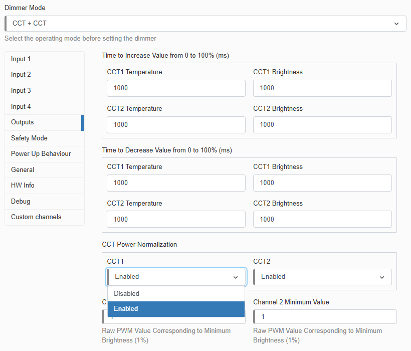
Note that total CCT strip power is not normalised by default. At 50% colour temperature, maximum power is the sum of the warm and cool channel maxima. For example, a 9.6 W/m strip comprising two 4.8 W/m channels produces its maximum light output at 9.6 W/m.
Firmware 3.7.0 introduced total CCT power normalisation. Enable it under the group Outputs → parameter CCT Power Normalization. With normalisation enabled, the same 9.6 W/m strip produces a maximum output corresponding to 4.8 W/m regardless of colour temperature.
Input configuration
Press types and actions
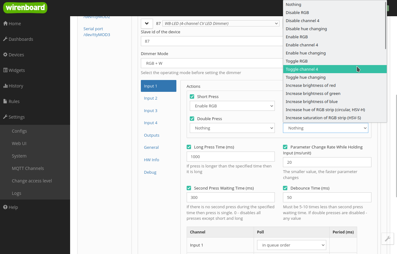
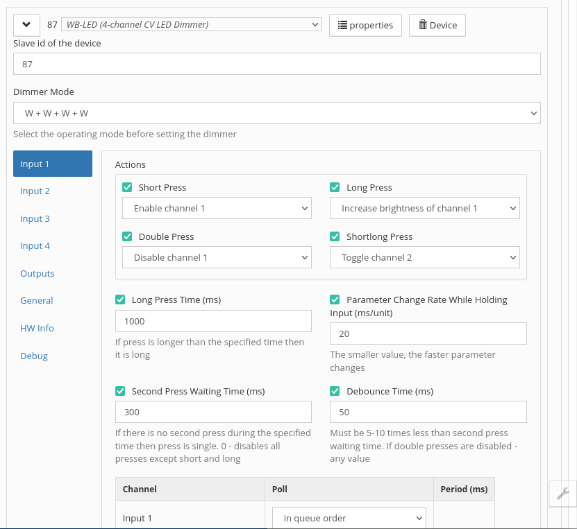
Assign actions to short, long, double and short-then-long presses. Inputs can also use latching switches. See Press-type recognition.
For each input and press type, select an action such as on, off, toggle or increase/decrease a value. Maintained-switch actions are off, on and toggle.
Features:
- If increase/decrease is selected while the channel is off, activating its brightness input switches it on at minimum brightness and always dims upwards.
- Dimming down stops at 1%, rather than zero.
- If the action changes a parameter other than brightness, such as Hue, an off channel does not change. A button therefore cannot change the colour of an unlit strip.
Select actions separately for each input and press type on the tab Mode → groups Actions for input x, where x is the input number.
Latching switches have fixed ON and OFF positions. They support only Off, On and Toggle actions.
Step of Value Change for single and double presses
Available from firmware 3.8.0
For Increase value and Decrease value actions assigned to short or double presses, configure a value increment independently for each input and each of these press types.
The increment uses the selected channel's units: percent for brightness and saturation (0–100), degrees for RGB Hue (0–360), and milliseconds for hue-change period. Values are clamped at the channel limit; for example, increasing brightness from 80% by 50 sets it to 100%.
A short or double press changes the channel target by the configured increment. The transition follows the Time to Increase Value from 0 to 100% (ms) and Time to Decrease Value from 0 to 100% (ms) settings for that brightness, colour-temperature or colour channel.
Parameters
For each input you can also change:
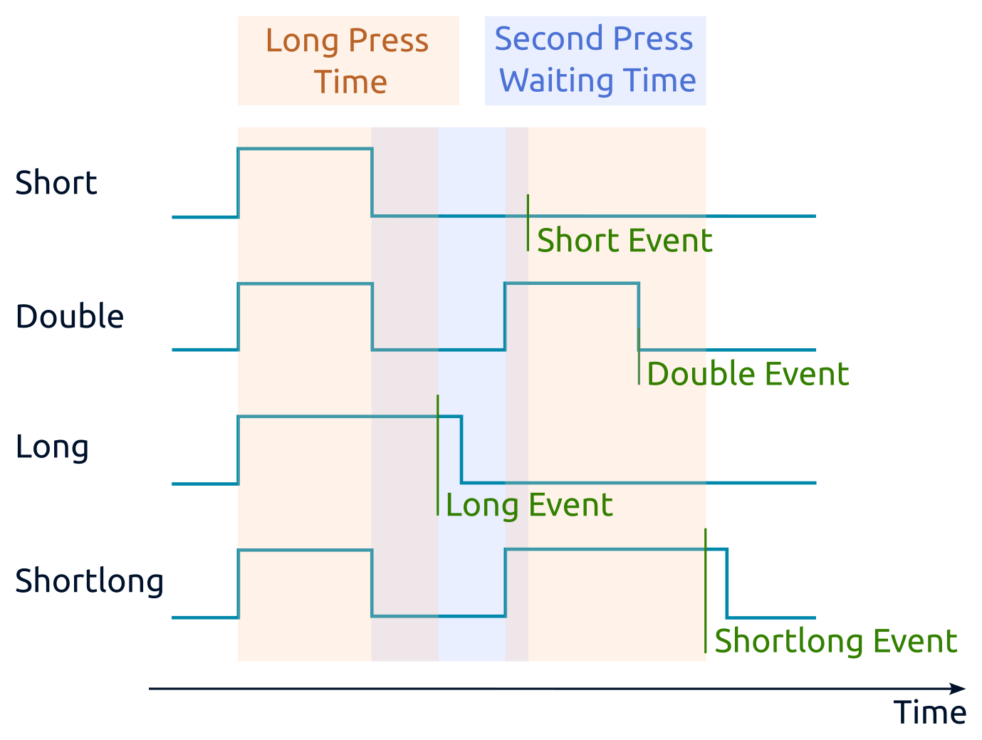
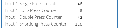
- Long Press Time (ms) — distinguishes long and short presses. A press lasting longer than this value is long; otherwise it is short.
- Second Press Waiting Time (ms) — opens a time window after a short press ends. A second press within this window is treated as a double press; otherwise the first press is treated as a single press.
- Debounce Time (ms) — the input signal must remain stable for this duration before it is accepted and processed by the press-recognition algorithm. For press recognition, set it to one fifth to one tenth of the second press waiting time.
- Polling interval for each counter — leave this at the default value; the driver manages polling automatically.
Double-press detection delays short-press detection. For example, with the default 300 ms setting, the short-press event occurs 300 ms after the button is released. If double presses and short-then-long presses are not required, set Second Press Waiting Time (ms) to 0 ms. The short-press event will then occur immediately after button release.
Press recognition takes place after debouncing. With Debounce time set to the default 50 ms, presses shorter than 50 ms are ignored. Button release is also registered 50 ms after physical release. Choose the debounce time for the particular button to minimise latency while preventing false events, such as a double press being detected instead of a single press.
- Parameter Change Rate While Holding Input (ms/unit) — used by increase/decrease actions such as brightness control. Lower values give faster changes.
Configure these parameters on the tab Input x, where x is the input number.
Encoder support
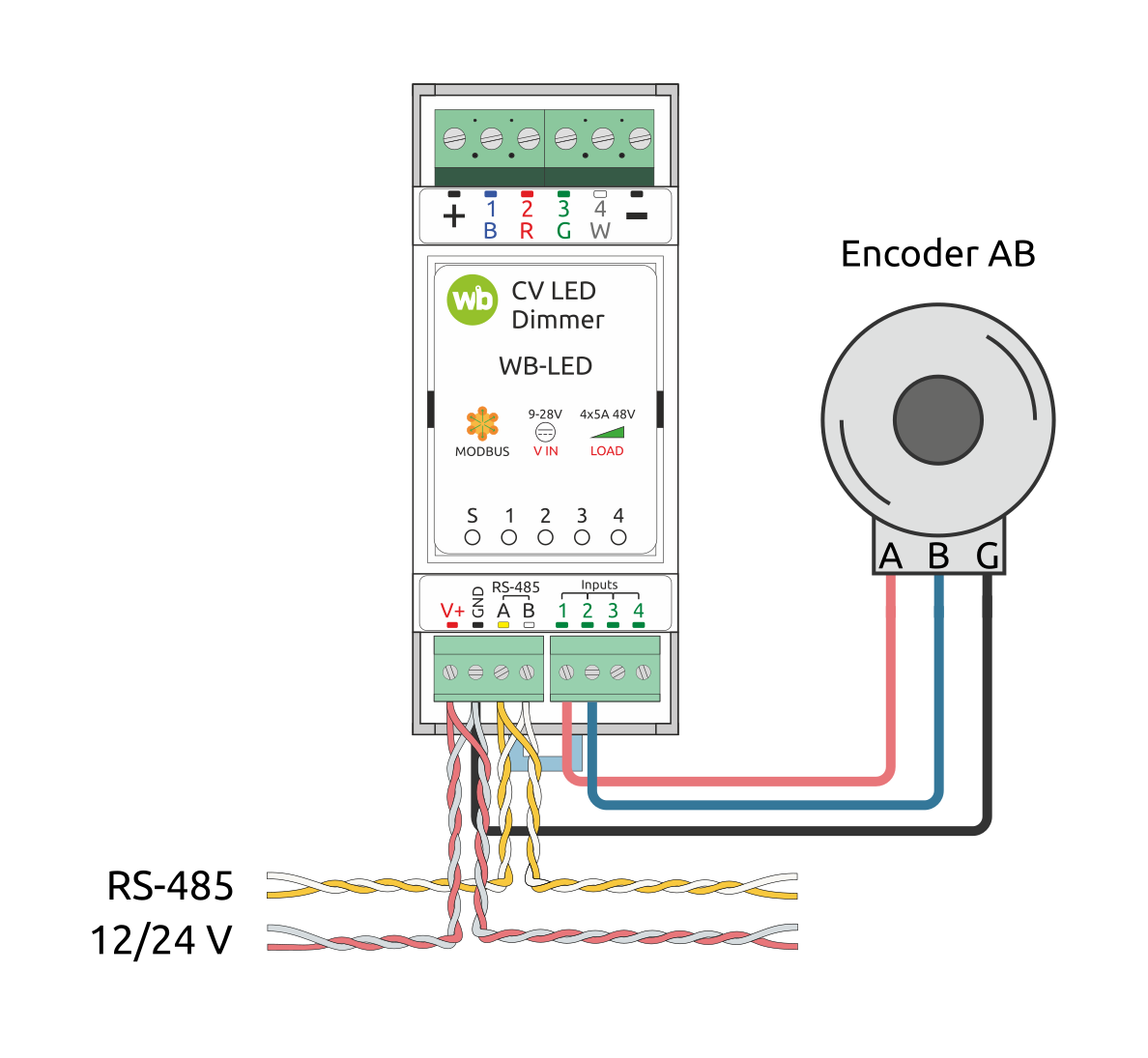
Available from firmware 3.8.0
Up to two AB quadrature/incremental encoders can be connected: Encoder 1 uses inputs 1/2, Encoder 2 uses inputs 3/4.
For each encoder input, configure Debounce time. Recommended debounce time: 2–5 ms; use 2 ms for fast rotation.
Encoder pulse rate must not exceed 250 pulses per second with 2 ms debouncing, otherwise counting errors may occur. Encoders with up to 25 pulses per revolution are recommended to provide frequency margin.
AB encoders
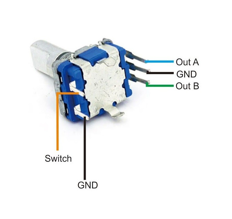
AB encoders can control parameters such as lighting brightness.
Connect three wires: A, B, GND. Shaft position is available in the channel Encoder position from −2147483648 to 2147483647. At a boundary it wraps to the opposite end of the range and continues counting.
Many encoders also have a Switch output that closes to GND when the shaft is pressed. Connect it to any free input and process it as an ordinary button.
Channel Encoder position is writable, allowing an initial position to be set.
Controlling the dimmer with an encoder
Open device settings and select the tab Encoders. Configure each encoder separately under Encoder N.
The parameter Encoder Connection Type select AB type.
Parameter Pulses per Step sets how many A/B input pulses correspond to one logical encoder step.
The parameter Controlled Channel selects the channel changed by rotation. Available channels depend on the selected dimmer mode.
Parameter Step of Value Change sets the change per logical encoder step.
Parameter Behavior When Brightness is Reduced Below the Minimum Value determines whether dimming below the configured minimum switches the channel off or leaves it at minimum brightness.
Output configuration
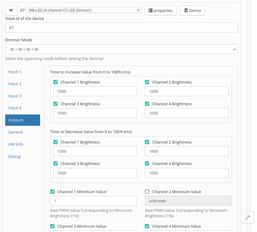
Configure change rates, dimming limits and PWM frequency.
Reduce PWM frequency when using the amplifier WB-AMPLED or when closely routed dimmer cables interfere with one another.
Configure these parameters on the tab Outputs.
Channel dimming limits
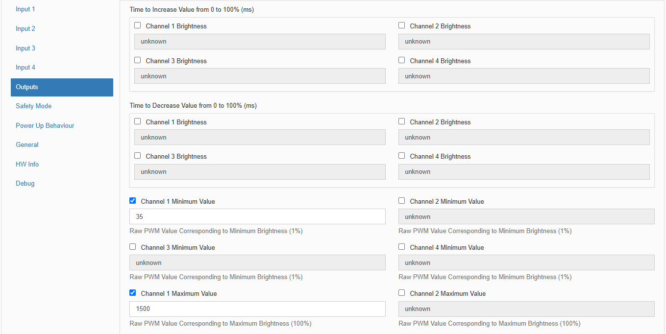
Dimming limits set minimum brightness or restrict maximum LED-strip brightness.
Dimming level uses relative PWM units. By default the range is 1 at the lower limit to 2048 at the upper limit, corresponding to 1% and 100% channel brightness.
Configuration:
- In the template settings, under Diagnostics enable polling of Channel N Raw PWMto display its PWM value in the device widget.
- Open the tab Devices and adjust strip brightness to determine the PWM values required for the lower and upper dimming limit.
- In the template settings, under Outputs set the new values for the lower and upper dimming limits of the relevant channel and save the settings.
Output channels with automatic switch-on
Available from firmware 3.8.0 Each output-control channel has an additional auto-on channel. It mirrors the ordinary channel, but writing a value greater than zero also switches the associated output on.
Behaviour:
- writing > 0 — switches the output on and sets the written value;
- Writing 0 — switches the channel off or resets its level in the same way as the ordinary channel;
- reading returns the current value of the corresponding parameter.
Auto-on registers for each channel are listed in the register map.
Auto-on channels are useful for automation and external integrations: a single command sets the desired level or colour without a separate coil write to switch on.
For non-brightness parameters such as Hue, zero is a valid value rather than an off command: 0° Hue means red. Writing zero therefore switches the output on at that value. These channels always switch on their associated outputs regardless of the value written.
Remote smooth adjustment of lighting parameters
Available from firmware 3.8.0
Without this feature, smooth remote changes require the master to write a new level every few milliseconds, loading the RS-485 bus and slowing polling of other devices. With Auto-Change the master writes an action once, and the dimmer changes the parameter step by step at the configured interval.
Each parameter has two registers:
- Auto-Change — action:
- 0 — stop changing,
- 1 — decrease,
- 2 — increase,
- 3 — alternate decreasing and increasing; the initial direction is opposite to the last local long-press direction for that parameter;
- Period Auto-Change — duration of one step in milliseconds.
Available parameters depend on the dimmer mode: individual W channels, combined channels, CCT brightness and colour temperature, RGB/HSV parameters, and shared 2*CCT parameters.
The following behaviour results from the Auto-Change registers acting as a remote button: they mirror holding a local button for the same parameter. Local and remote control therefore react identically to range limits, off channels and Safety Mode, allowing a local-button action to be reproduced through Modbus.
Behaviour details:
- For bounded parameters — brightness, CCT colour temperature, RGB components and HSV saturation — smooth changes stop at the range limit . The dimmer resets the action register to zero and publishes an event when it stops.
- Hue (HSV-H) changes cyclically over 360°: after 360° comes 0°; before 0° comes 359°. It does not stop automatically. Write 0 to the action register or enter Safety Mode to stop it. Switching the channel off through its coil only pauses hue cycling; it resumes at the same point when switched on again.
- Increasing brightness on an off channel automatically switches it on at 1% and continues increasing, as with a held local button.
- All other actions on an off channel — decreasing brightness or changing colour temperature, RGB, saturation or hue — leave the action active but do not change the parameter until the channel is switched on. Changes then resume without another action write.
- Switching off through a coil register does not reset Auto-Change. Final channel levels are sent to the master immediately. If an increase-brightness action was active, the next step switches the channel on again.
- On entering Safety Mode all active Auto-Change sequences stop: action registers are cleared and final levels are sent to the master.
- Level-register events are sent at most once every 500 ms per register during an active sequence. The final value, on stopping or reaching a limit, is always sent immediately. This leaves bus capacity for other devices and for the master's remote-button reads and writes.
Safety Mode
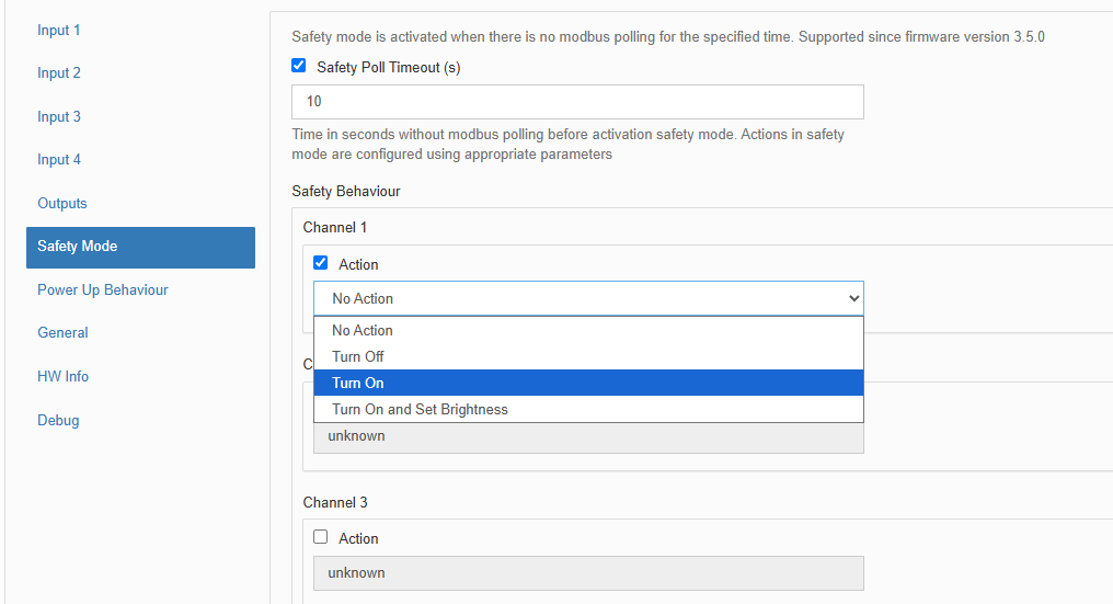
Safety Mode can stop a process if control of the module is lost, for example because the RS-485 cable is severed. Account for communication loss when designing control systems.
The fail-safe timer restarts after every successfully received and processed Modbus packet. When it expires, the module enters Safety Mode. Normal operation resumes when communication returns. The default timeout is 10 seconds.
Each output has a configurable fail-safe state and can be configured to enter it on communication loss.
Input control behaviour can be configured:
- Don't change — configured input control remains available.
- Disable in safety mode — inputs cannot control outputs during fail-safe operation.
- Enable only in safety mode — configured input control is available only in Safety Mode, not during normal operation.
Power Up Behaviour
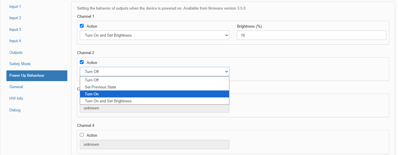
For each channel, select its power-on behaviour:
- Off;
- Restore previous state;
- On;
- On and set brightness.
Modbus operation
Wiren Board devices use Modbus RTU. The physical connection uses the RS-485.
interface. All main commands for reading and writing one or multiple registers are supported. See the list in the Modbus protocol description.
The module can be configured:
- in the Wiren Board controller web interface;
- using the Wiren Board device web configurator;
- using third-party software.
Default port settings
| Value default |
Parameter name in the web interface |
Parameter |
|---|---|---|
| 9600 | Baud rate | Baud rate, bit/s |
| 8 | Data bits | Number of data bits |
| None | Parity | Parity |
| 2 | Stop bits | Number of stop bits |
In current firmware, setting Stop bits is optional: the device also operates correctly when its number of stop bits differs from the Modbus master setting.
For a faster response, we recommend increasing the baud rate to 115200 bit/s; see Communication parameter settings
Modbus address
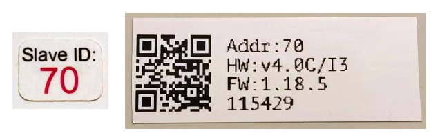
Each device on the bus must have a unique address from 1 to 247. The factory-assigned address is printed on labels on the enclosure (top cover, side or underside). Devices in a production batch are assigned different addresses, so devices in one order will usually have different addresses.
For instructions on finding, changing or resetting the address, see Wiren Board device Modbus address.
Default configuration
Factory settings use RGB+W mode with these input actions:
- Input 1 controls RGB channels: a short press toggles them, and a long press increases/decreases strip brightness.
- Input 2 changes RGB Hue on a long press.
- Input 3 controls W: a short press toggles it, and a long press increases/decreases brightness.
- Input 4 is not configured.
Other parameter defaults are listed in the register map.
Fast Modbus extension
Fast Modbus extends standard Modbus with rapid discovery of Wiren Board devices on RS-485 and event polling.
These features are enabled by a special command from the master, so Wiren Board devices remain compatible with third-party equipment.
Not every register supports event generation. Check the register map: event-capable registers are marked with ⚡. See Fast Modbus.
Register map
Firmware updates and resetting settings
Wiren Board devices support firmware updates over Modbus. This allows bugs to be fixed at the installation site and, where technically possible, new features to be added. Settings stored in the device are retained during a firmware update.
Instructions:
- Firmware update ()
- Resetting settings
- Connection parameter settings
- Modbus address: find, reset or change
- Updating the bootloader
New firmware releases are listed in the firmware changelog.
Software
WB-LED dimmer firmware behaviour — description of the embedded software operation.
Known issues
Hardware revisions
Device images and drawings
CorelDRAW 2018 (font: Ubuntu): File: WB-Library.cdr.zip
Visio:
- Wiren Board devices: File: WB-Visio-Lib.zip.
- Enclosures, circuit breakers, contactors and other third-party symbols.

Module dimensional drawing (DXF): File: WB-LED.dxf.zip
Module dimensional drawing (PDF): File: WB-LED.dxf.pdf
AutoCAD Electrical schematic symbol library: File: Wirenboard-AE-base.zip
-
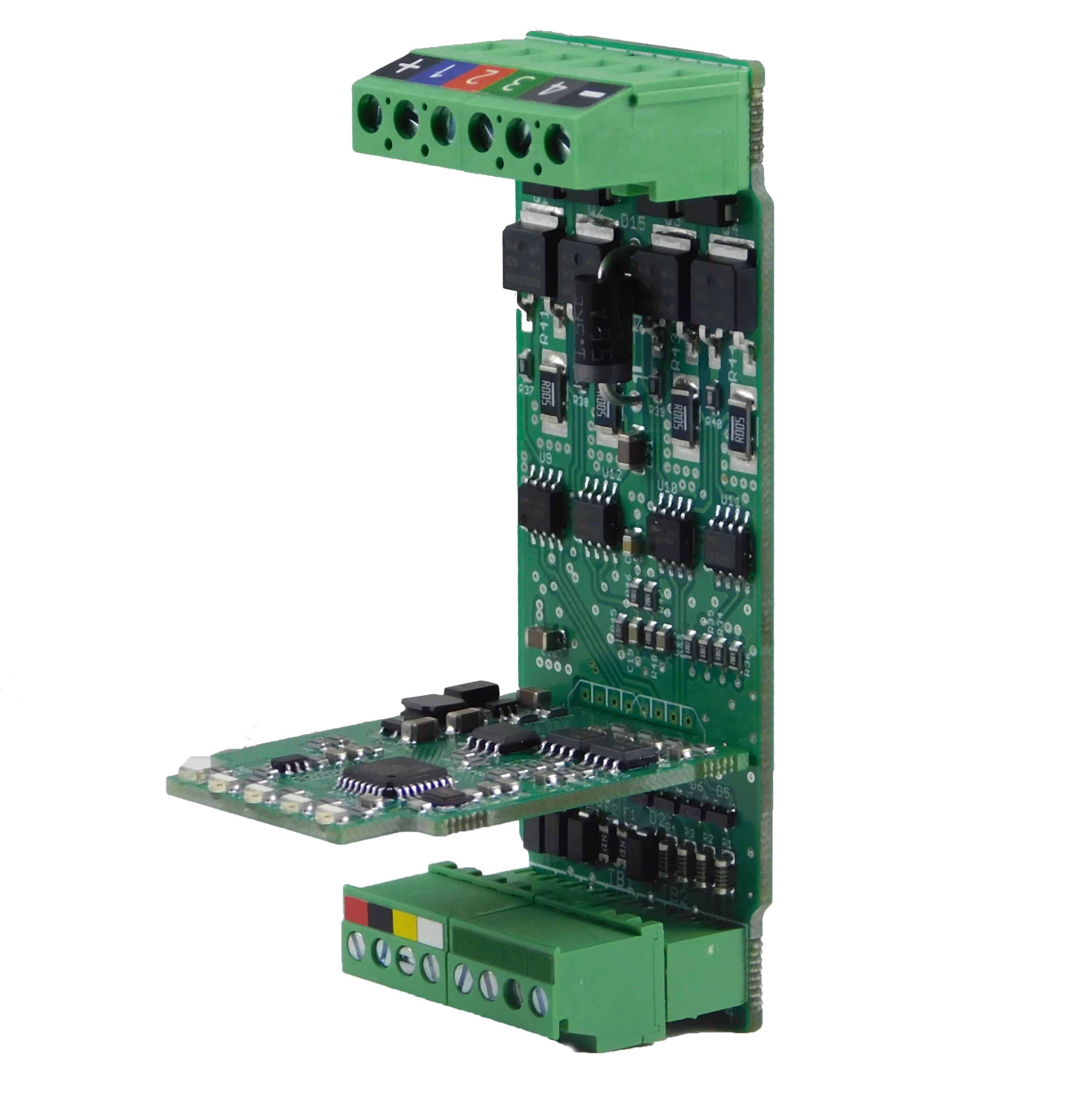 WB-LED PCB
-
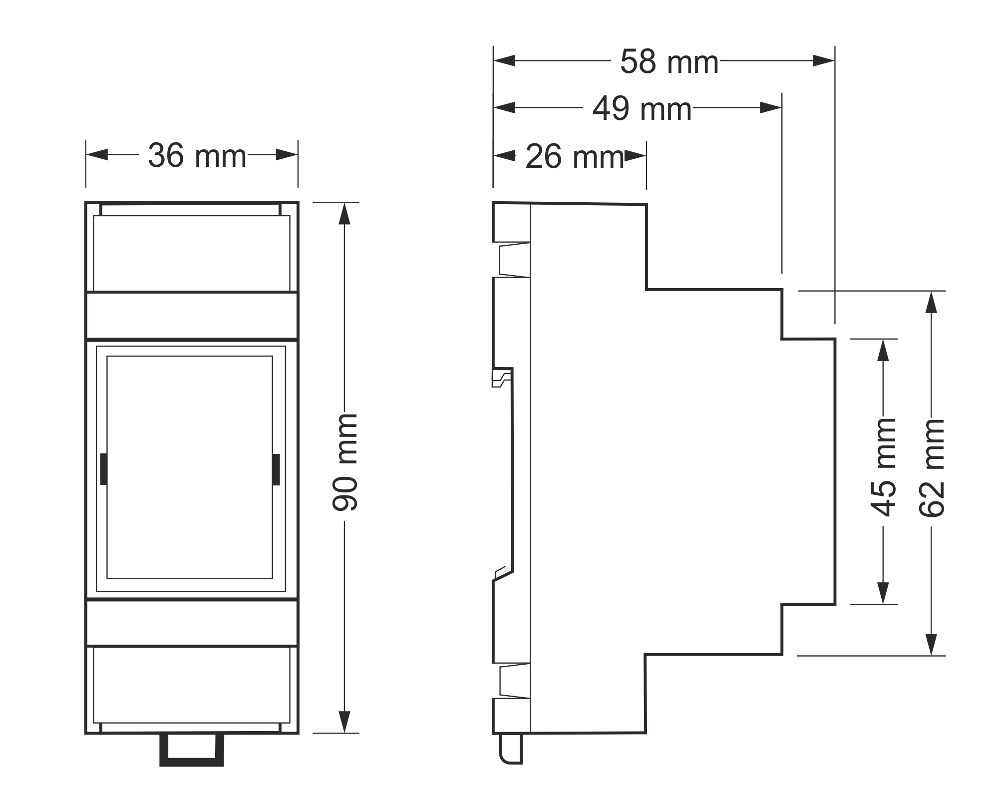 Overall dimensions