 Documentation
WB-MDM3-300W
3-channel mains dimmer
Covered order codes (1)
WB-MDM3-300W
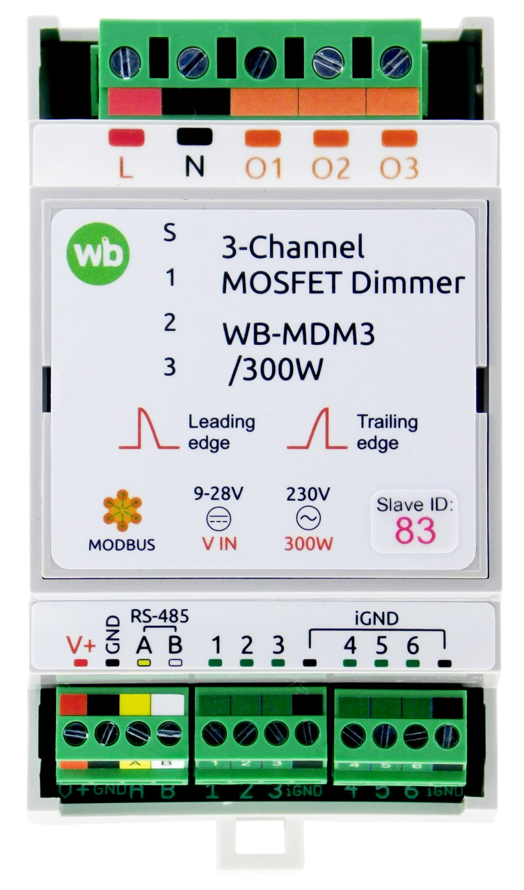
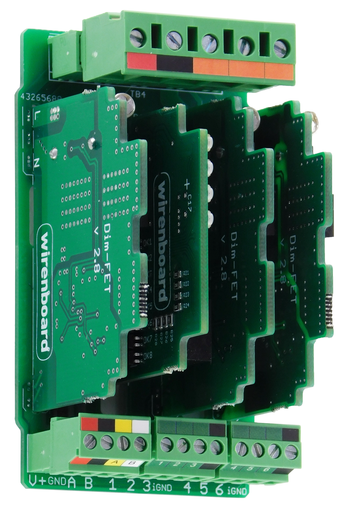
Purpose
The WB-MDM3 three-channel dimmer controls the brightness of lighting powered from 230 VAC mains: incandescent lamps and dimmable LED lamps, LED strip drivers, electronic transformers for halogen lamps and similar equipment.
In leading-edge mode, WB-MDM3 can regulate fans rated up to 30 W. Fans may hum slightly and the control range is approximately 50–100%. If unsuitable, use a variable-frequency drive such as T13-750W-12-H or an equivalent.
Each channel supports independent operating modes:
- leading-edge and trailing-edge phase control;
- two dimming curves: one for incandescent and LED lamps, and one for resistive loads;
- switching mode — on/off without dimming, similar to a silent relay, for non-dimmable loads;
- dim night-time switch-on;
- flexible pushbutton control settings.
Do not connect channels in parallel. If the load exceeds one channel's rating, divide it into separate groups across multiple channels.
Technical specifications
| Parameter | Value |
|---|---|
| Power supply | |
| Interface supply voltage | 9–28 V DC |
| Power consumption |
0.4 W |
| Outputs | |
| Output type | Field-effect transistors |
| Number of channels | 3 |
| Dimming curves | 2 |
| Rated switched voltage | 220–240 V, 50–60 Hz |
| Maximum power per channel
(/300 W version) |
300 W — incandescent lamps
180 W — dimmable LED lamps up to 150 W — induction and universal motors in switching mode up to 30 W — induction and universal motors in dimming mode |
| Inputs | |
| Purpose | 6 brightness-control inputs |
| Input isolation | Galvanically isolated inputs. Approximately 12 VDC at the input and approximately 2 mA when closed |
| Permissible voltage | −20 V to +40 V |
| Indicators | |
| LED | See Indicators |
| Control | |
| Control interface | RS-485 |
| Interface isolation | Non-isolated |
| Communication protocol | Modbus RTU; software-configurable address; factory settings are printed on the label |
| RS-485 interface parameters | Software-configurable; defaults:
baud rate — 9600 bit/s; data — 8 bits; parity — none (N); stop bits — 2 |
| Ready after power-on | ~2 s |
| Operating conditions | |
| Ambient air temperature | −40 to +80 °C |
| Relative humidity | Up to 95%, non-condensing |
| Climatic classification under GOST 15150-69 | O2.1* |
| Warranty | 2 years |
| Service life | 8 years |
| Terminal blocks and wire cross-sections | |
| Recommended wire cross-section with insulated wire-end ferrules | control inputs: 0.35–1 mm2 — single ferrule; 0.35–0.5 mm2 — twin ferrule,
power inputs: up to 2.5 mm2 — single ferrule; up to 1.5 mm2 — twin ferrule |
| Standard ferrule sleeve length | 8 mm |
| Screw tightening torque | control inputs: 0.2 N·m,
power outputs: 0.5 N·m |
| Dimensions | |
| Width, DIN modules | 3 |
| Overall dimensions (L × W × H) | 53 × 90 × 58 mm |
| Weight (including box) | 155 g |
Operating principle
Indicators
The module has indicators that show its status without connecting to a controller:
- S (green) — Modbus communication status: lights up when low-voltage power is applied and flashes during polling over RS-485. On devices with events enabled in Fast Modbus ⚡ the indicator flashes more frequently than during sequential polling because events are polled faster. In bootloader mode it flashes once per second; during firmware upload it flashes rapidly.
- 1–3 (red) — output state; indicator brightness follows the output brightness setting.
Security
WB-MDM3 has three protection mechanisms: thermal, overcurrent and fire protection.
Thermal protection
A thermistor near the power transistors trips at 95–100 °C and resets after cooling to 75 °C. High load or inadequate cooling causes repeated shutdown and restart.
Overcurrent protection
Trip threshold is approximately 7 A. Restart is attempted after 0.5 s. The limit corresponds to roughly 400–500 W of incandescent load and provides overload and short-circuit protection. However, fault-current rise depends on the resistance and inductance of the wiring and supply cable. A short, thick cable and a fault at the voltage waveform peak may cause a current pulse too steep and large for protection to respond in time. Complete short-circuit protection is therefore not guaranteed.
Fire protection
A fuse protects against fire if the other protection mechanisms fail. If it blows, the power transistors have generally also failed. Circuit breakers usually act more slowly than the fuse and cannot be relied upon to prevent damage to the dimmer itself.
A typical failed experiment may damage both transistors and fuse and also trip the circuit breaker.
Installation
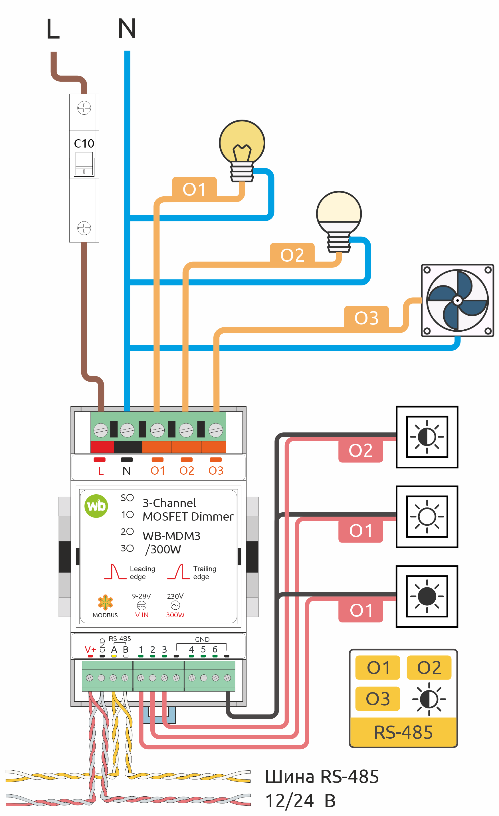
The first output uses two-button control, the second one-button control, and the third Modbus-only control. These settings differ from the defaults
Mount the device on a standard 35 mm DIN rail.
The V+ GND A B terminal block, with a 3.5 mm pitch, connects the power supply and RS-485 communication bus. Correct bus wiring is essential for reliable communication; see RS-485 bus wiring and connection.
If devices on the RS-485 bus use different power supplies, their GND terminals must be interconnected. See Grounding Wiren Board devices and connecting GND and iGND.
Digital inputs activate when connected to iGND. The current is low (~2 mA), so any suitable button or switch type can be used. Cable length and cross-section are not critical for contact detection. To reduce interference from nearby power wiring, use twisted pair and connect iGND to the second conductor of the pair. More about connecting iGND/GND terminals.
Both phase L and neutral N must be connected to the dimmer; otherwise it will not operate. Check mains presence at L and N using AC on L-N in the web interface.
Dimming produces some interference on power wiring; route it away from audio cables.
Installation example
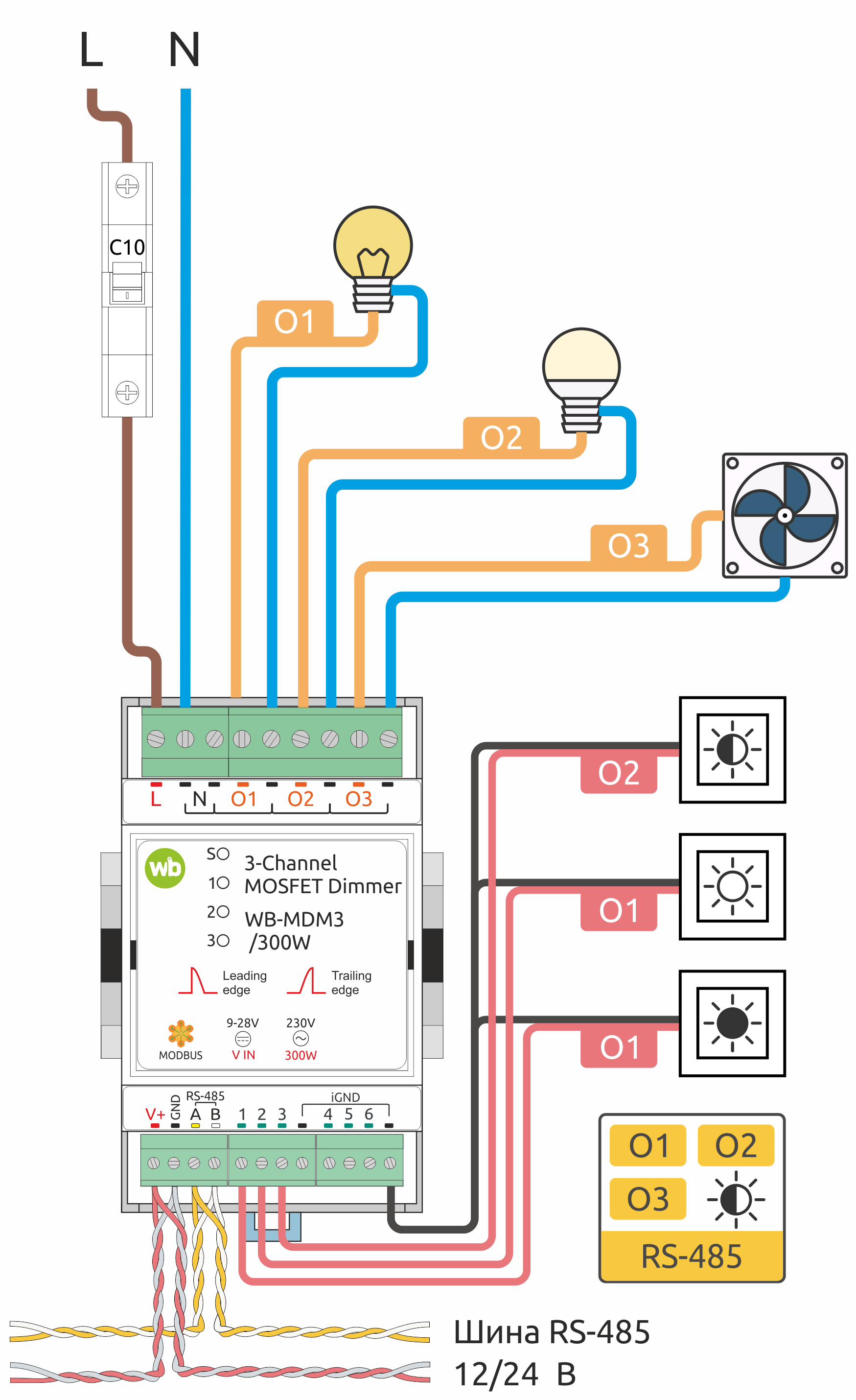
One possible WB-MDM3 load connection is shown in the diagram WB-MDM3 installation example.
The example uses a 10 A circuit breaker before the dimmer. Select its rating for the installed conductor cross-section.
Loads connected to outputs O1–O3 include a fan, an LED lamp and an incandescent lamp.
In the example, O1 uses two pushbuttons and O2 one pushbutton. All three channels can be controlled over RS-485.
In this example, O1–O2 use trailing-edge dimming, while O3 uses leading-edge dimming. For mode selection, see Phase-cut dimming mode.
For other module settings, see Configuration.
Using LED lamps
Not all dimmable lamps perform well. Many manufacturers offer numerous models, and products sold under the same name may differ internally. Test the lamps before buying them for an entire building. Poorly matched lamps may have a narrow dimming range, flicker or fail prematurely.
If unsure whether the dimmer works correctly, test it with a low-power incandescent lamp, up to 100 W; this is a reliable reference load.
Wiren Board controller web interface
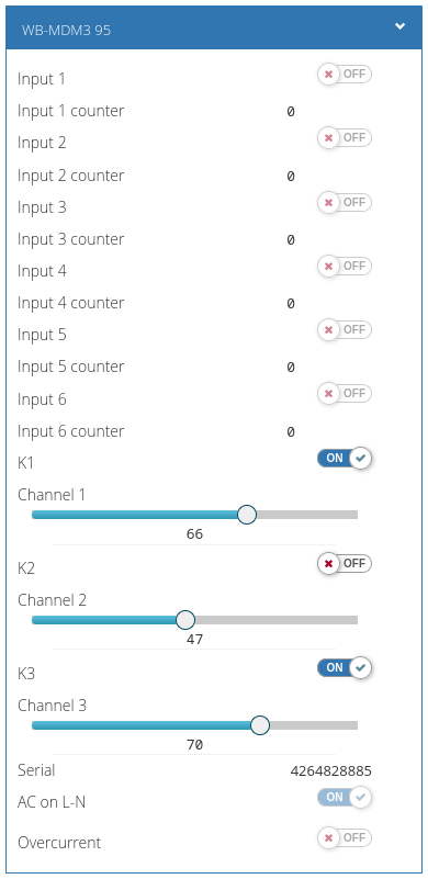
Selecting a template
To display the device on the Devices tab of the Wiren Board controller web interface, add it automatically by scanning for Wiren Board devices on RS-485 or manually by selecting the template WB-MDM3.
Dimmers from batch v2.6B and earlier (firmware 2.6.6) require the legacy template. In /etc/wb-mqtt-serial.conf replace tpl1_wb_mdm3 with WB-MDM3 and run systemctl restart wb-mqtt-serial. The “Device template is outdated” warning is expected.
Controlling the device and viewing values
The web interface allows you to control device outputs and view readings. To change the displayed channels, edit the device configuration in the wb-mqtt-serial driver settings.
The following controls are available by default:
- Switches K1 – K3 turn each channel on and off without losing the brightness setting.
- Sliders Channel 1 – 3 set each channel's brightness manually from 0 to 100%.
- Indicators Input 1 – 6 show input states.
- The counters Input 1 – 6 counter show the number of input-to-ground closures since dimmer power-on.
- AC on L-N — voltage present at dimmer terminals L and N. Useful for diagnostics: it should normally be ON.
- Serial — device serial number.
- Overcurrent — overcurrent flag, available only on revisions v2.6D and later. Unsupported hardware shows this parameter in red; disable channel polling in the settings.
Configuration
Configuration methods
- Set the parameters in the Wiren Board controller web interface under Settings → Configs → Serial devices driver configuration. If these items are unavailable, check your access level.
- Write settings to the Modbus registers of the module from the controller console using the utility modbus-utils-rpc or modbus_client.
- Without a Wiren Board controller, use the Wiren Board device web configurator or other software; see Using Wiren Board Modbus devices without a controller. You will need a computer with an interface converter: USB-RS485.
Our devices are continually improved. If settings described in this manual are missing, update the device firmware and controller software.
Input control mode
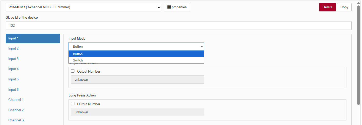
Two input control modes are available:
- Momentary pushbutton — detects four press types: short, long, double and short-then-long. Each can trigger an action on a specified channel.
- Latching switch — digital input mode for an ordinary latching switch with two stable positions.
Momentary pushbutton
WB-MDM3 provides six digital inputs for pushbuttons, each detecting four press types: short, long, double and short-then-long. This gives 24 events, each with two mapping parameters: the output and the action.
Output number selects the output affected by the event. Choose one output, all outputs, or none to ignore the event.
Output action selects what the event does:
- switch the channel on;
- switch the channel off;
- toggle channel state;
- increase the output level;
- decrease the output level;
- increase/decrease the output level.
Some event/action combinations are not meaningful and are ignored.
| Available event and action combinations | ||||||
|---|---|---|---|---|---|---|
| Press type | Switch output off | Switch output on | Toggle output state | Increase level | Decrease level | Increase/decrease level |
| Single press | One / all outputs | One / all outputs | One output | One / all outputs | One / all outputs | Unavailable |
| Long press | One / all outputs | One / all outputs | One output | One / all outputs | One / all outputs | One output |
| Double press | One / all outputs | One / all outputs | One output | One / all outputs | One / all outputs | Unavailable |
| Short-then-long press | One / all outputs | One / all outputs | One output | One / all outputs | One / all outputs | One output |
Dimming step for single and double presses
Available from firmware 2.12.0
For Increase level and Decrease level actions assigned to a short or double press, the brightness step is configurable separately for each channel and each of those press types.
A short or double press changes the target brightness by the configured step. The transition is smooth, according to Channel N Increase Rate (ms/%) and Channel N Decrease Rate (ms/%).
Latching switch
A latching switch has two stable positions, like an ordinary domestic light switch. Only Switch off, Switch on and Toggle actions are available:
- Select input mode Latching switch.
- Assign channel actions for the positions on and off.
- Click Save settings.
If these parameters are absent, the controller software is older. See alternative configuration methods under Configuration methods.
Encoder support
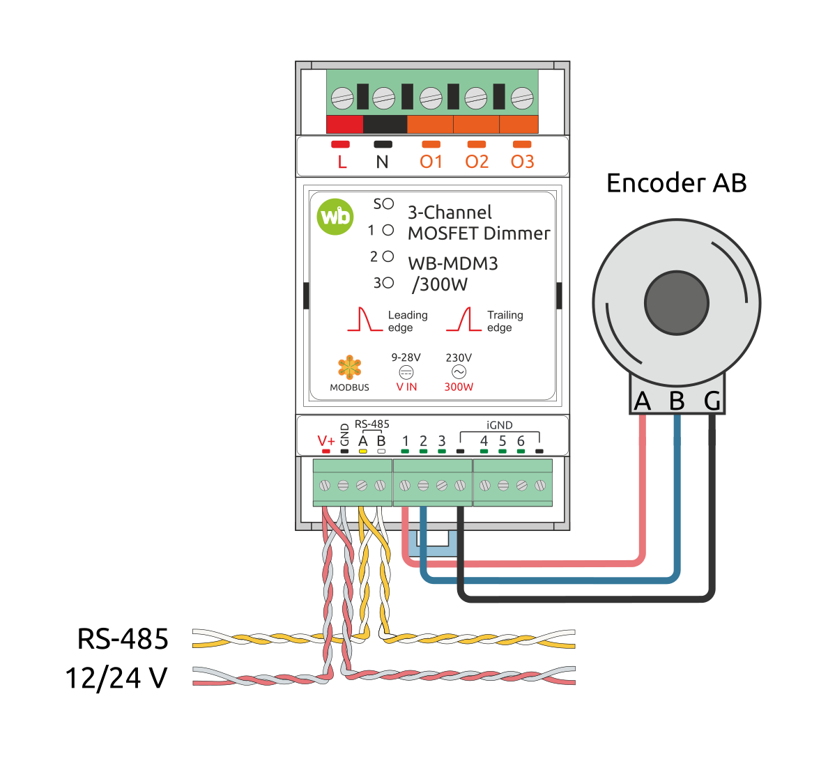
Available from firmware 2.12.0
Up to three AB quadrature incremental encoders can be connected to WB-MDM3 inputs: Encoder 1 uses inputs 1/2, Encoder 2 — inputs 3/4, Encoder 3 — inputs 5/6.
For each encoder input, configure Debounce time. Recommended debounce time: 2–5 ms; use 2 ms for fast rotation.
Encoder pulse rate must not exceed 250 pulses per second with 2 ms debouncing, otherwise counting errors may occur. Encoders with up to 25 pulses per revolution are recommended to provide frequency margin.
AB encoders
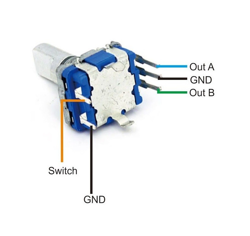
AB encoders can control parameters such as lighting brightness.
Connect three wires: A, B, GND. Shaft position is available in the channel Encoder position from −2147483648 to 2147483647. At a boundary it wraps to the opposite end of the range and continues counting.
Many encoders also have a Switch output that closes to GND when the shaft is pressed. Connect it to any free input and process it as an ordinary button.
Channel Encoder position is writable, allowing an initial position to be set.
Controlling the dimmer with an encoder
Open device settings and select the tab Encoders. Configure each encoder separately under Encoder N.
The parameter Encoder Connection Type select AB type.
Parameter Pulses per step sets how many A/B input pulses correspond to one logical encoder step.
The parameter Controlled Channel select the channel controlled by encoder rotation: Control disabled or channel 1–3.
Parameter Level adjustment step (%) sets the change per logical encoder step.
Parameter Behaviour below minimum level determines whether reducing the level below its configured minimum switches the channel off or retains the minimum level.
Load type
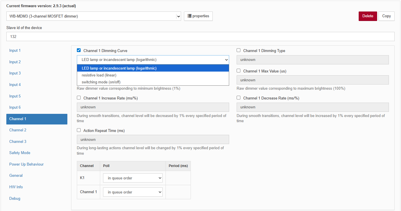
The parameter Channel X dimming curve sets the relationship between voltage and dimming level for different load types:
- LED or incandescent lamp (logarithmic brightness curve) (default) — smooth lighting adjustment from 0 to 100%;
- resistive load (linear brightness curve) — power proportional to dimming level;
- switching mode — for non-dimmable loads: the channel switches fully on regardless of the brightness setting.
Phase-cut dimming mode
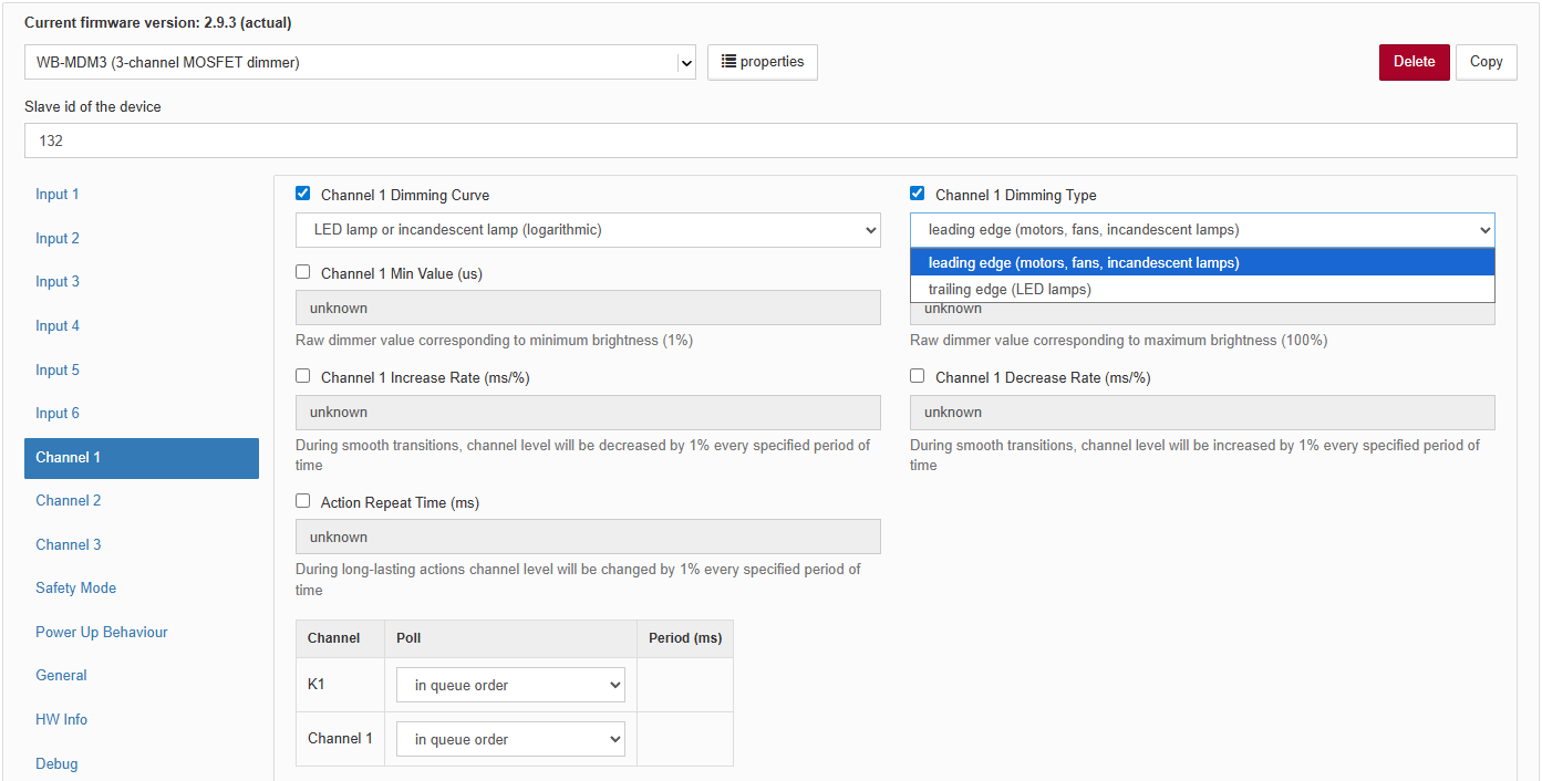
Selecting the wrong mode may damage the dimmer itself.
WB-MDM3 provides leading-edge (RL) and trailing-edge (RC) control for compatibility with different dimmable devices.
Before connecting dimmable power supplies, consult their instructions to select the mode. Trailing-edge (RC) operation is usually required.
Select the mode independently for each channel using Dimming mode. Leading-edge dimming is the default.
| Load type | Dimming mode |
|---|---|
| Inductive loads: fans with induction or universal motors rated up to 30 W | Only leading-edge (RL),
operation; the other mode permanently damages the dimmer. |
| Resistive loads: incandescent lamps |
Both modes are permitted. |
| Capacitive loads: LED lamps and dimmable LED power supplies |
Mode trailing-edge (RC). Some dimmable LED lamps flicker strongly in this mode; in that case, use leading-edge dimming. |
Minimum dimming level
Lamps have different minimum turn-on thresholds.
Set the lower dimming threshold separately for each channel. It cannot exceed Maximum dimming level. The default is 1000 µs.
To ensure the lamp lights at 1% brightness, adjust the lower threshold:
- Set the parameter Minimum dimming level to 1000 µs.
- Set the required channel brightness to 0% and switch it on.
- Gradually increase brightness until the lamp lights.
- Read Channel N Raw Duty (us) and enter it as the Lower dimming threshold. In the Wiren Board web interface, enable register polling Channel N Raw Duty (us) under Diagnostics.
Check that the lamp lights after being off for one minute, allowing the capacitors in its driver to discharge.
-
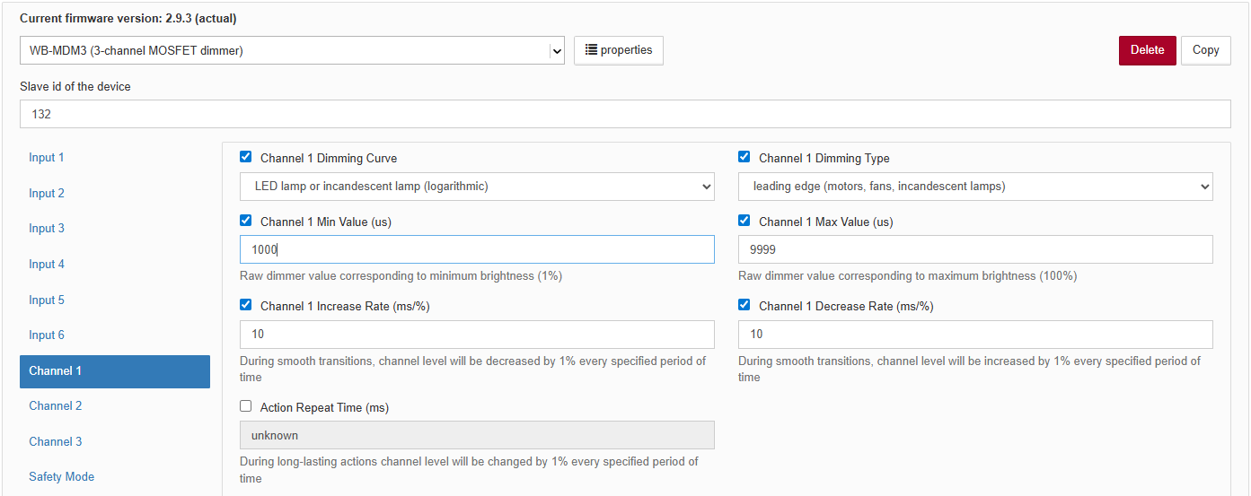 Setting the lower dimming threshold
-
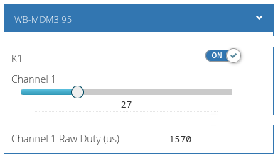 Channel control and channel raw value
Maximum dimming level
Some lamps stop increasing in visible brightness above a particular setting.
Set the upper dimming threshold separately for each channel. It cannot be below Minimum dimming level.
To obtain smooth brightness adjustment, configure the upper threshold:
- Set the parameter Maximum dimming level to 9999 µs.
- Set the required channel brightness to 100% and switch it on.
- Decrease the setting until the lamp's brightness starts to change.
- Read Channel N Raw Duty (us) and enter it as the Upper dimming threshold. In the Wiren Board web interface, enable register polling Channel N Raw Duty (us) under Diagnostics.
Typical values are about 6000 for LED lamps and 9999 for incandescent lamps. The default is 9999.
-
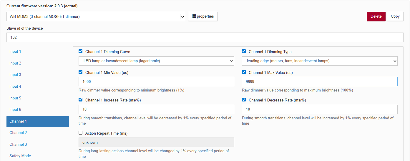 Setting the upper dimming threshold
-
Channel control and channel raw value
Dimming transition time
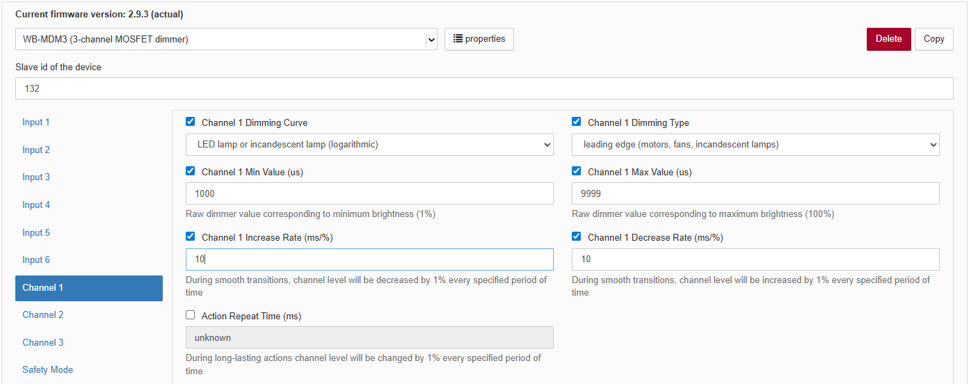
Brightness transition speed is configured separately for each channel and for increasing/decreasing brightness, in milliseconds per 1% brightness. The default is 10 ms/%, so switching a channel to 100% produces a ramp of 100 × 10 = 1000 ms = 1 second.
Set transition speed separately for each channel using Channel N Increase Rate (ms/%) and Channel N Decrease Rate (ms/%).
If Channel N Increase Rate (ms/%) is 0 ms/% and current brightness is 0% (channel off), a new brightness setting is still not applied instantaneously because of inrush protection. The transition to 1% takes at least 200 ms.
On/off switching mode
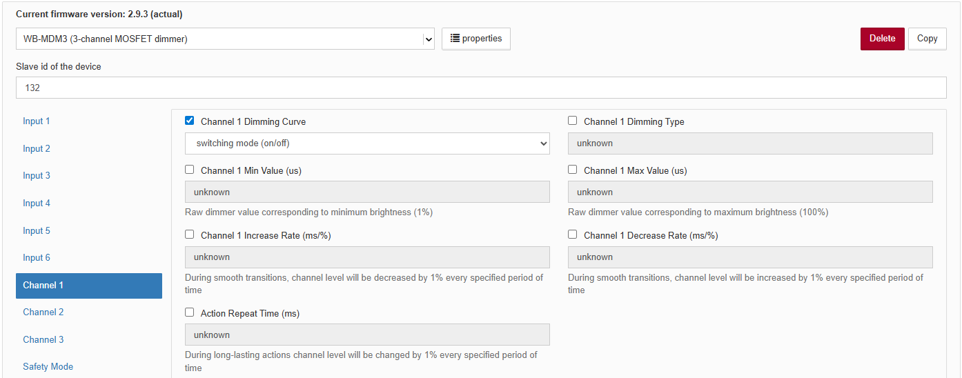
For non-dimmable loads, select switching mode. Brightness is ignored: the channel switches fully on or off using K1–K3 or a short button press.
For switching-mode configuration, see Load type.
Output channels with automatic switch-on
Available from firmware 2.12.0 Each output-control channel has an additional auto-on channel. It mirrors the ordinary channel, but writing a value greater than zero also switches the associated output on.
Behaviour:
- writing > 0 — switches the output on and sets the written value;
- Writing 0 — switches the channel off or resets its level in the same way as the ordinary channel;
- reading returns the current value of the corresponding parameter.
Auto-on channels are useful for automation and external integrations: a single command sets the desired level without a separate coil write to switch the channel on.
Safety Mode
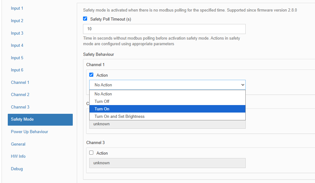
Safety Mode can stop a process if control of the module is lost, for example because the RS-485 cable is severed. Account for communication loss when designing control systems.
The fail-safe timer restarts after every successfully received and processed Modbus packet. When it expires, the module enters Safety Mode. Normal operation resumes when communication returns. The default timeout is 10 seconds.
Each output has a configurable fail-safe state and can be configured to enter it on communication loss.
Input control behaviour can be configured:
- Do not block — configured input control remains available.
- Block in Safety Mode — inputs cannot control outputs during fail-safe operation.
- Allow only in Safety Mode — configured input control is available only in Safety Mode, not during normal operation.
Output states at power-up
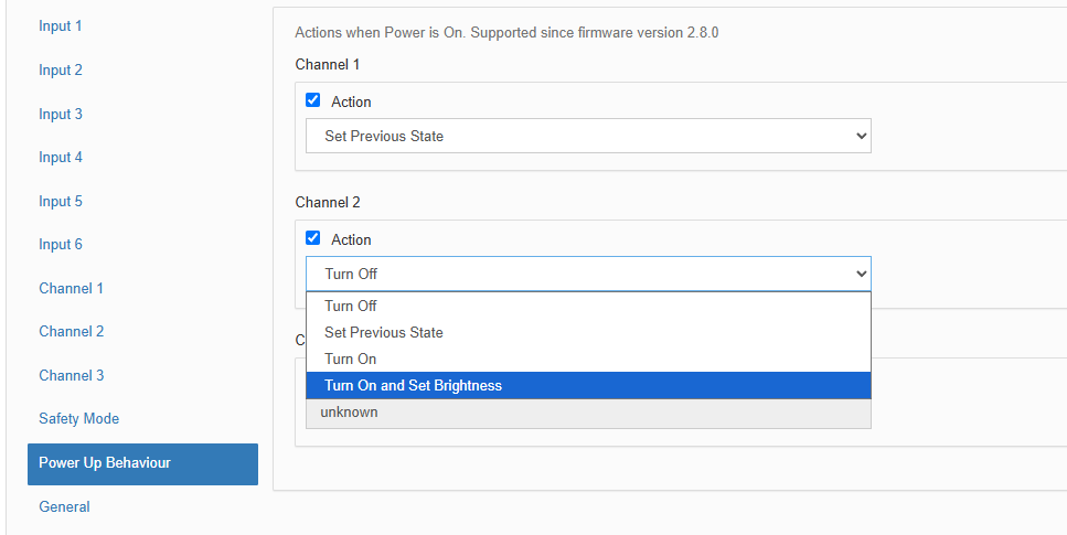
For each channel, select its power-on behaviour:
- Switch off — the channel can subsequently be enabled by its switch or by changing brightness from 0% to N%;
- Restore previous state — restores the channel state before the power loss;
- On;
- Set brightness — switches the channel on at the configured level. A 0% setting switches it off; changing brightness from 0% to N% switches it on.
Modbus operation
Wiren Board devices use Modbus RTU. The physical connection uses the RS-485.
interface. All main commands for reading and writing one or multiple registers are supported. See the list in the Modbus protocol description.
The module can be configured:
- in the Wiren Board controller web interface;
- using the Wiren Board device web configurator;
- using third-party software.
Default port settings
| Value default |
Parameter name in the web interface |
Parameter |
|---|---|---|
| 9600 | Baud rate | Baud rate, bit/s |
| 8 | Data bits | Number of data bits |
| None | Parity | Parity |
| 2 | Stop bits | Number of stop bits |
In current firmware, setting Stop bits is optional: the device also operates correctly when its number of stop bits differs from the Modbus master setting.
For a faster response, we recommend increasing the baud rate to 115200 bit/s; see Communication parameter settings
Modbus address
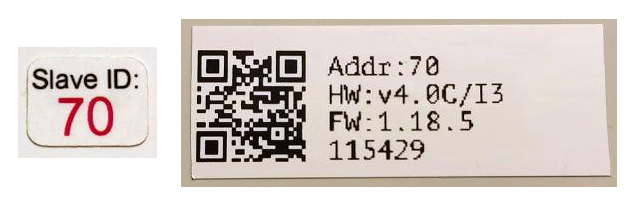
Each device on the bus must have a unique address from 1 to 247. The factory-assigned address is printed on labels on the enclosure (top cover, side or underside). Devices in a production batch are assigned different addresses, so devices in one order will usually have different addresses.
For instructions on finding, changing or resetting the address, see Wiren Board device Modbus address.
Remote smooth brightness adjustment
Available from firmware 2.12.0
Without this feature, smooth remote dimming must be implemented by the master, repeatedly writing level values every few milliseconds and increasing RS-485 traffic and the polling cycle for other devices. With Auto-Change the master writes an action once, and the dimmer periodically adjusts brightness as if a local button were held.
Action register values:
- 0 — stop smooth adjustment;
- 1 — decrease brightness;
- 2 — increase brightness;
- 3 — alternate between decreasing and increasing brightness, like the local Increase/decrease level action. The initial direction is opposite to the last local long-press direction on that channel.
Adjustment stops at 1% or 100% brightness, or when the channel is switched off through its coil. The dimmer then clears the action register to 0 so the master can see the current state.
The adjustment speed follows the local button action-repeat setting, which also determines adjustment while an input is held.
Fast Modbus extension
Fast Modbus extends standard Modbus with rapid discovery of Wiren Board devices on RS-485 and event polling.
These features are enabled by a special command from the master, so Wiren Board devices remain compatible with third-party equipment.
Not every register supports event generation. Check the register map: event-capable registers are marked with ⚡. See Fast Modbus.
Register map
Channel and brightness control
Write coil registers to switch channels on or off. Set brightness by writing 1–100 to the brightness register, where 1 is the minimum lit level. Writing 0 switches the channel off and clears its coil. A subsequent nonzero brightness write switches it on and sets the coil to 1.
Firmware updates and resetting settings
Wiren Board devices support firmware updates over Modbus. This allows bugs to be fixed at the installation site and, where technically possible, new features to be added. Settings stored in the device are retained during a firmware update.
Instructions:
- Firmware update ()
- Resetting settings
- Connection parameter settings
- Modbus address: find, reset or change
- Updating the bootloader
New firmware releases are listed in the firmware changelog.
Software
WB-MDM3 dimmer software — description of the embedded software operation.
Known issues
Hardware revisions
Device images and drawings
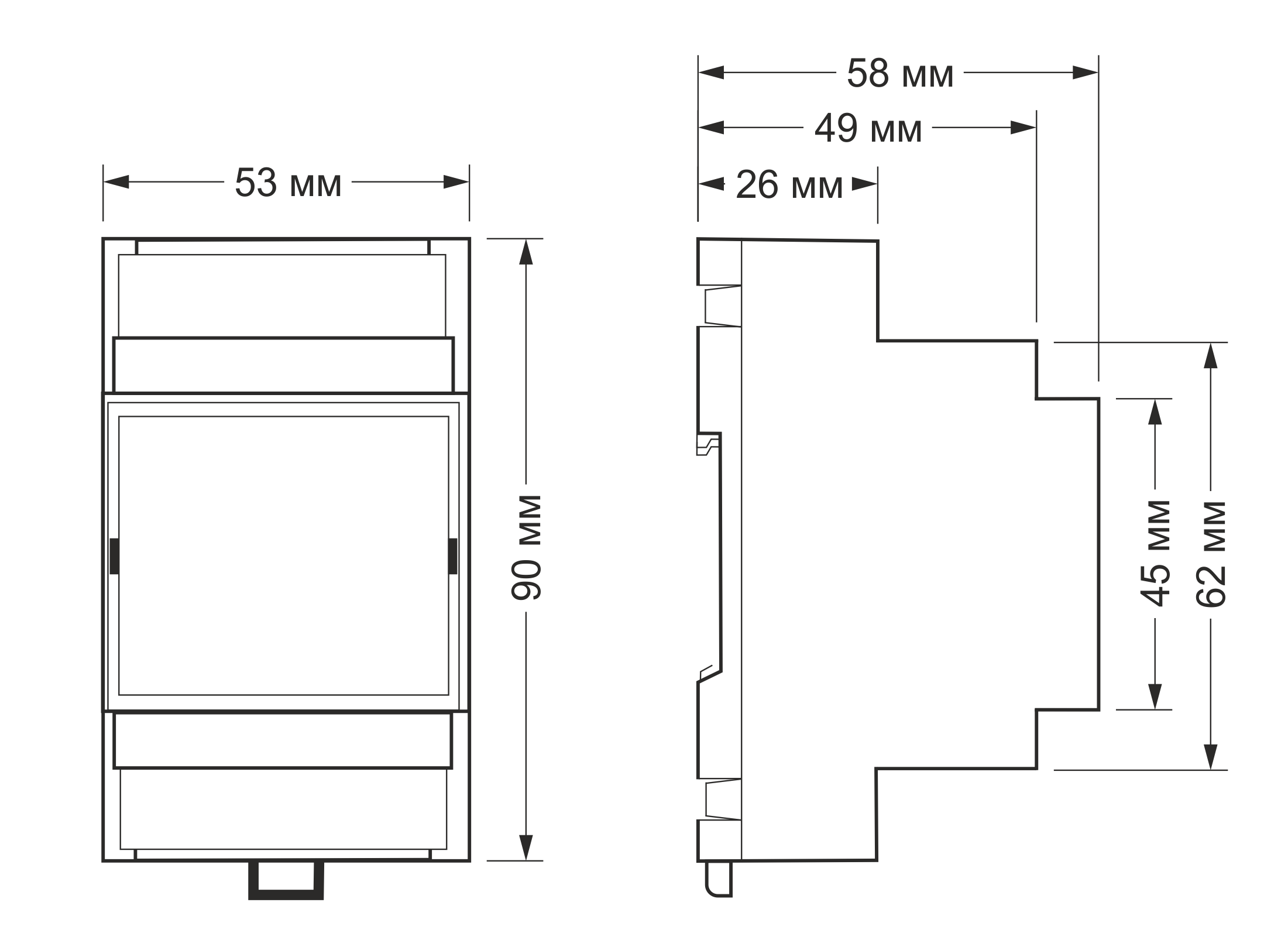
CorelDRAW 2018 (font: Ubuntu): File: WB-Library.cdr.zip
Visio:
- Wiren Board devices: File: WB-Visio-Lib.zip.
- Enclosures, circuit breakers, contactors and other third-party symbols.

Autocad 2013 DXF: File: WB-MDM3.dxf.zip
AutoCAD Electrical schematic symbol library: File: Wirenboard-AE-base.zip
Images and diagrams for earlier hardware versions
-
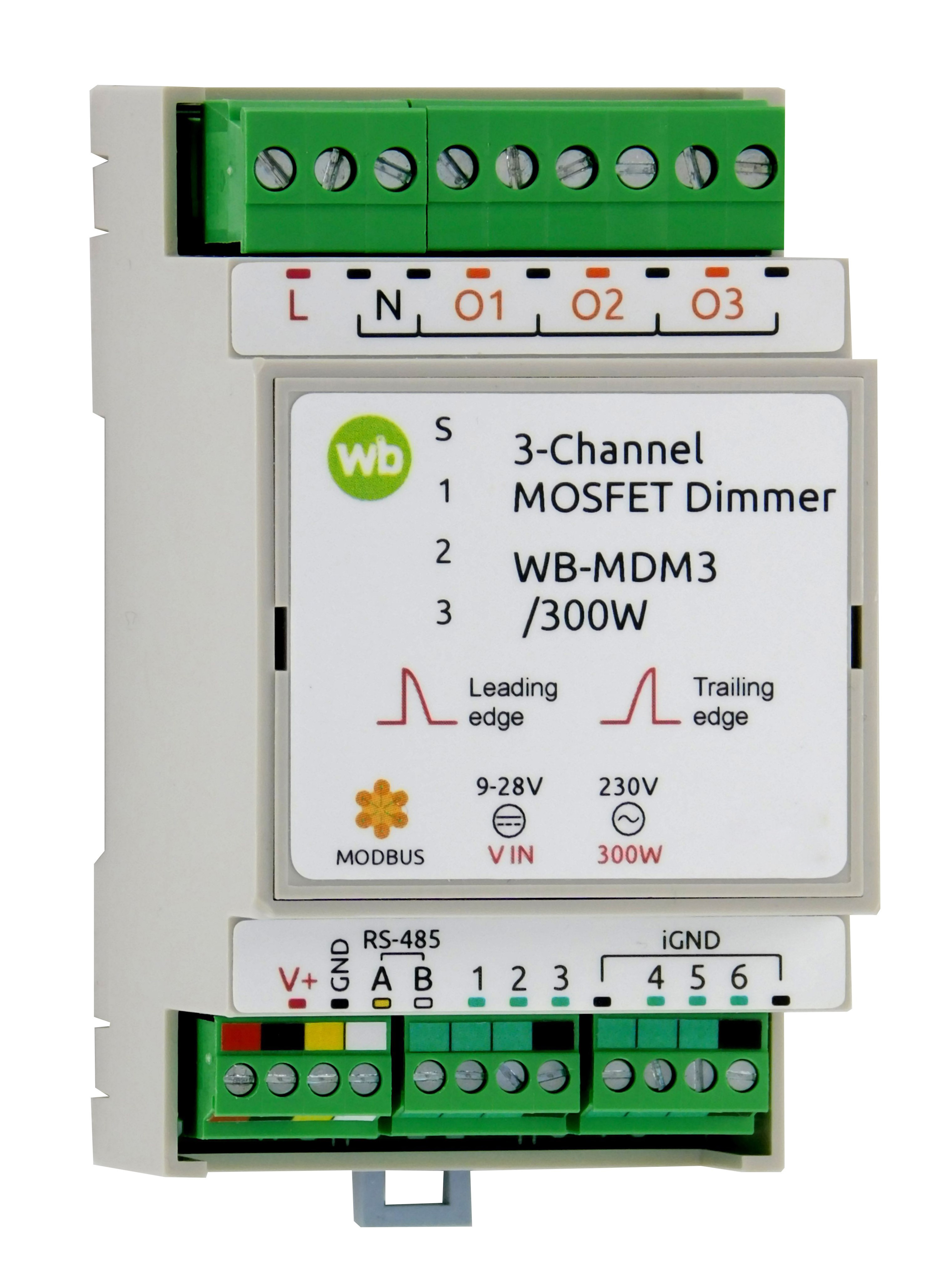 WB-MDM3 before revision v2.10
-
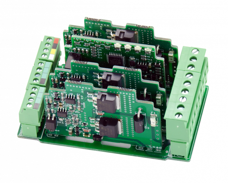 WB-MDM3 PCB before revision v2.10
-
 WB-MDM3 connection diagram before revision v2.10