 Documentation
WBE2-DI-DR-3
3-channel dry-contact input expansion module
Covered order codes (1)
WBE2-DI-DR-3
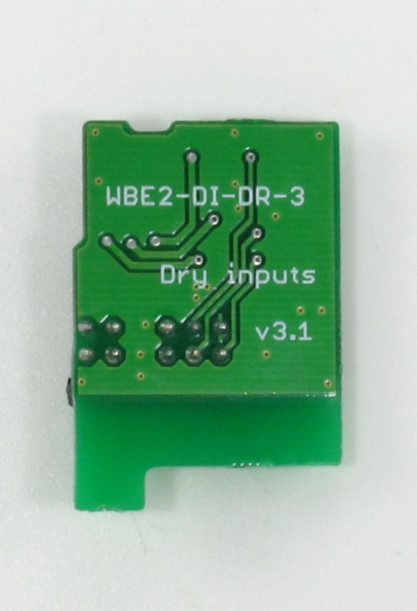
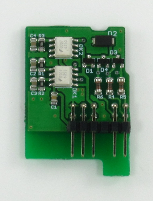
Module overview
A three-channel module for connecting sensors and meters with dry-contact or open-collector outputs.
Logic 0: the input is floating.
Logic 1: the input is connected to the controller ground (GND), either directly or through a resistance of no more than 300 Ω.
The module has no hardware pulse-counting function. Pulse counting can be implemented in software, or by using a WB-MCM8 module. Example wb-rules rules: Counting pulses on a digital input.
Technical specifications
| Parameter | Value |
|---|---|
| Minimum detectable pulse width | 12 ms |
| Maximum pulse frequency | 40 Hz |
| Warranty | 2 years |
| Service life | 8 years |
Expansion module terminals:
| Terminal | Function |
|---|---|
| O1 | Input 1 |
| O2 | Input 2 |
| O3 | Input 3 |
Installation
When modules are ordered together with a Wiren Board controller, the manufacturer installs them at the factory. You only need to configure the modules in the controller web interface .
If you purchased the modules separately, install them as follows:
- Open the controller enclosure.
- Install the module with the correct polarity: its locating tab must enter the slot on the controller PCB.
-
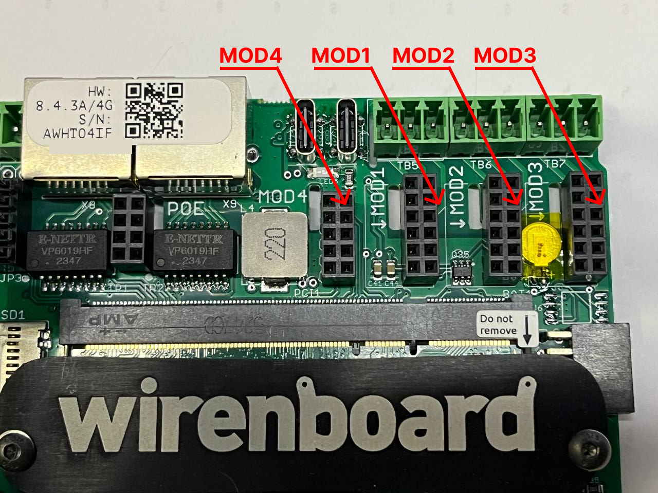 Expansion module port numbering (WB 6.7–8.4)
-
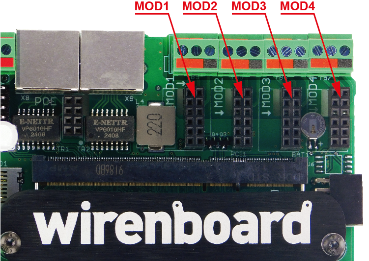 Expansion module port numbering (WB 8.5, 8M)
The module is compatible with all revisions of the Wiren Board 6, Wiren Board 7 and Wiren Board 8 controllers, subject to the compatibility table below:
| Model | WB6.3-6.6 | WB6.7/WB7 | WB8.4 | WB8.5 | |||||||||||
|---|---|---|---|---|---|---|---|---|---|---|---|---|---|---|---|
| MOD1 | MOD2 | MOD3 | MOD1 | MOD2 | MOD3 | MOD4 | MOD1 | MOD2 | MOD3 | MOD4 | MOD1 | MOD2 | MOD3 | MOD4 | |
| WBE2-DI-DR-3 | + | + | - | + | + | + | - | + | + | + | - | + | + | + | + |
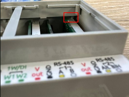
When installing the module in the MOD3 connector of a Wiren Board 6.7–8.4 controller, or in the MOD4 connector of a Wiren Board 8.5 controller, remove the obstructing tab on the controller enclosure using cutters or a file.
Configuration
Access permissions
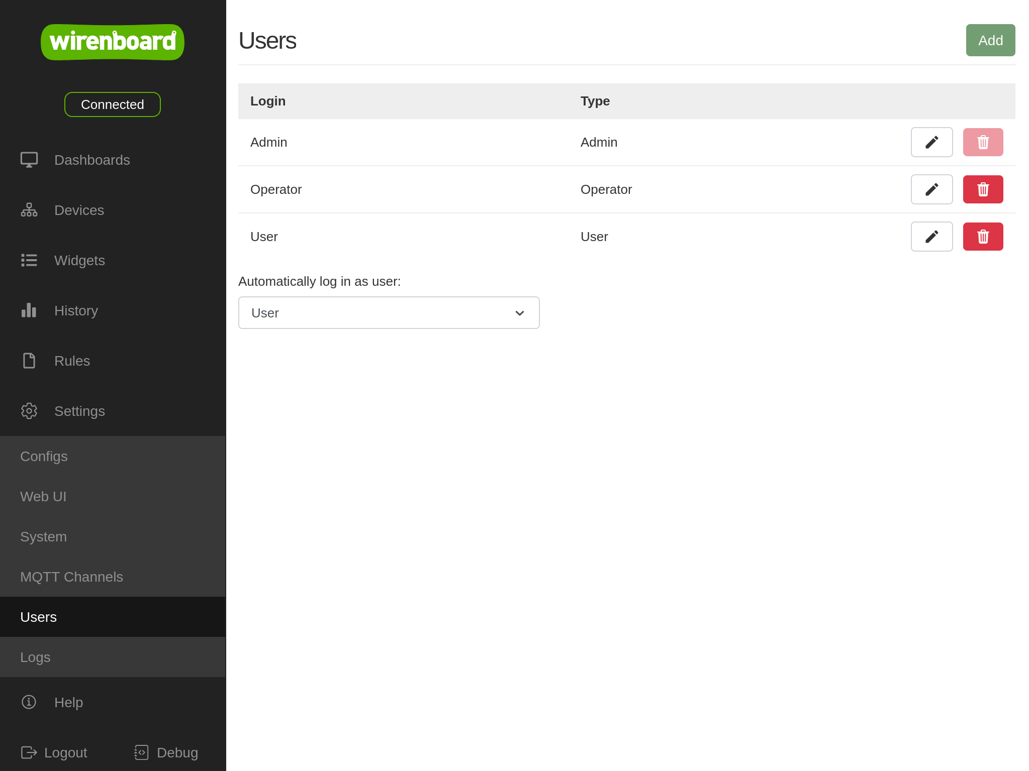
The access level depends on the user account. Users authenticate with a username and password. To change the controller settings, your account must have the following access level: Admin. User accounts are managed under Settings → Users. See User authentication and authorization.
In releases earlier than wb-2602 there are no user accounts; the access level is configured under Settings → Permissions.
Configuration
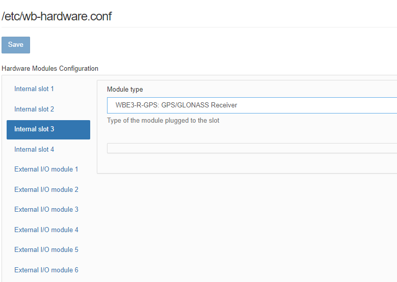
After physically connecting the module, add it to the controller configuration:
- In the web interface, open Settings → Configs → Expansion modules and ports and select the Internal slot in which the expansion module is installed.
- In the Module type list, select the name of the installed module.
- Click Save. The controller will enable the ports required by the module.
To remove a module from the configuration, select Not installed.
Controller integration
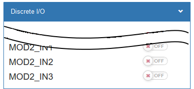
| Slot | Terminal | Input | Channel (MQTT) | Topic (MQTT) | GPIO name |
|---|---|---|---|---|---|
| MOD1 | O1 | IN1 | wb-gpio/MOD1_IN1 | /devices/wb-gpio/controls/MOD1_IN1 | MOD1 TX |
| O2 | IN2 | wb-gpio/MOD1_IN2 | /devices/wb-gpio/controls/MOD1_IN2 | MOD1 RX | |
| O3 | IN3 | wb-gpio/MOD1_IN3 | /devices/wb-gpio/controls/MOD1_IN3 | MOD1 RTS | |
| MOD2 | O1 | IN1 | wb-gpio/MOD2_IN1 | /devices/wb-gpio/controls/MOD2_IN1 | MOD2 TX |
| O2 | IN2 | wb-gpio/MOD2_IN2 | /devices/wb-gpio/controls/MOD2_IN2 | MOD2 RX | |
| O3 | IN3 | wb-gpio/MOD2_IN3 | /devices/wb-gpio/controls/MOD2_IN3 | MOD2 RTS | |
| MOD3 | O1 | IN1 | wb-gpio/MOD3_IN1 | /devices/wb-gpio/controls/MOD3_IN1 | MOD3 TX |
| O2 | IN2 | wb-gpio/MOD3_IN2 | /devices/wb-gpio/controls/MOD3_IN2 | MOD3 RX | |
| O3 | IN3 | wb-gpio/MOD3_IN3 | /devices/wb-gpio/controls/MOD3_IN3 | MOD3 RTS |
Hardware revisions
The batch number is printed on a label on the side of the enclosure or on the PCB.
| Revision | Batches | Release date | Changes from the previous revision |
|---|---|---|---|
| 3.4 | v3.4A, v3.4B, v3.4C, v3.4D - ... | 10.2023 - ... |
|
| 3.3 | v3.3A, v3.3B, v3.3C | 10.2022 - 10.2023 |
|
| 3.2 | v3.2A, v3.2B, v3.2C, v3.2D, v3.2E, v3.2F, v3.2G, v3.2H | 08.2020 - 10.2022 |
|
| 3.1 | ... | Before 08.2020 |
|