 Documentation
WBE2R-R-ZWAVE-ZWAY
Internal Z-Wave expansion module with Z-Way software licence
Covered order codes (1)
WBE2R-R-ZWAVE-ZWAY— Internal Z-Wave expansion module with Z-Way licence
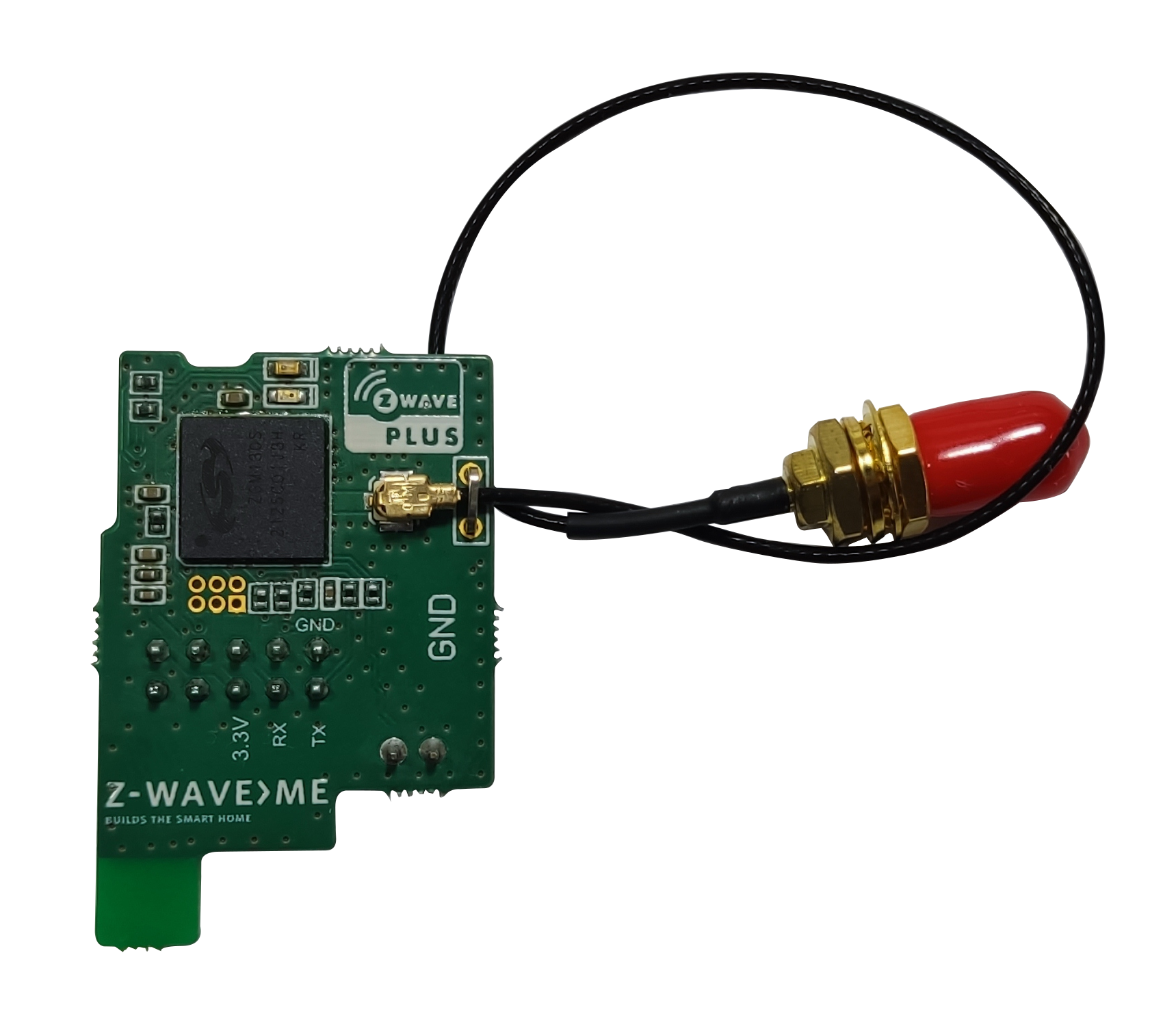
Module overview
The WBE2R-R-ZWAVE-ZWAY expansion module adds Z-Wave device support to a Wiren Board controller.
The module has no built-in antenna. Connect an external antenna through the RP-SMA connector. When a Wiren Board controller is ordered with the module, the external-antenna connector is factory-installed on the controller enclosure.
Technical specifications
| Parameter | Value |
|---|---|
| Protocol | Z-Wave |
| Z-Wave chip generation | 7 |
| Operating frequency | Software-selectable:
|
| Z-Wave.Me Z-Way software-stack licence | Yes |
| Maximum supported network devices | 232 |
| Power consumption, W | 0,15 |
| Warranty period | 2 years |
| Service life | 8 years |
The module supports the standard Zensys Serial API and is compatible with HomeSeer, Z-Command, mControl and LinuxMCE.
Installation
The module is compatible with all revisions of Wiren Board 6, Wiren Board 7 and Wiren Board 8 controllers; compatible slots are listed below:
| Model | WB6.3 — 6.6 | WB6.7/WB7 | WB8.4 | WB8.5 | |||||||||||
|---|---|---|---|---|---|---|---|---|---|---|---|---|---|---|---|
| MOD1 | MOD2 | MOD3 | MOD1 | MOD2 | MOD3 | MOD4 | MOD1 | MOD2 | MOD3 | MOD4 | MOD1 | MOD2 | MOD3 | MOD4 | |
| WBE2R-R-ZWAVE-ZWAY | + | + | + | + | + | + | + | - | + | + | - | + | + | + | + |
When modules are ordered with a Wiren Board controller, they are installed at the factory. You only need to configure the modules in the controller web interface.
If you purchased the modules separately, install them as follows:
- Disassemble the controller enclosure.
- Install the module with the correct orientation: the tab on the module must fit into the slot on the controller PCB.
-
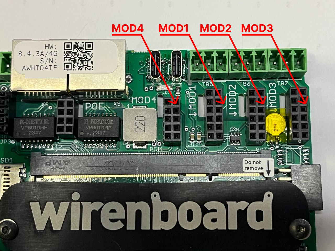 Expansion module port numbering (WB 6.7–8.4)
-
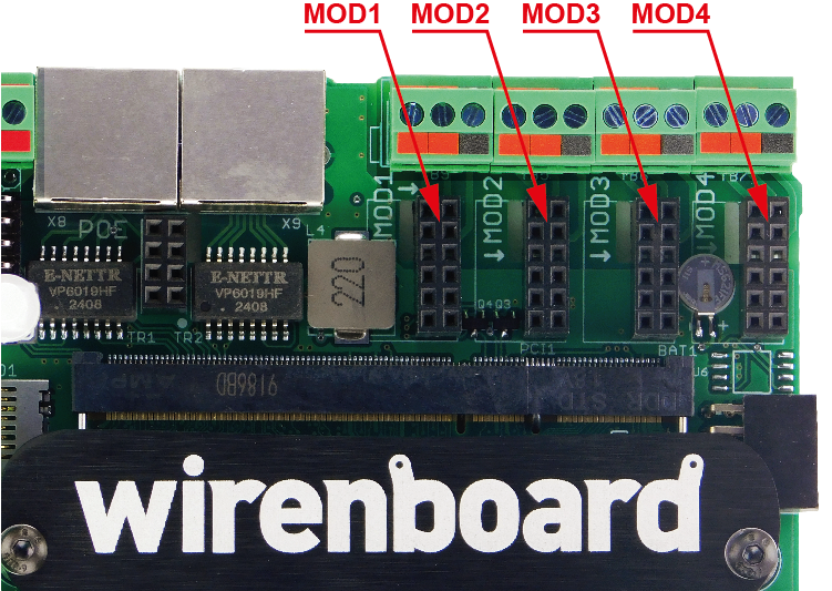 Expansion module port numbering (WB 8.5, 8M)
- Secure the SMA socket in the enclosure hole above the Ethernet connectors using its nuts. The socket and enclosure hole have a flat section that aligns the connector and prevents rotation. Enclosures earlier than Wiren Board 6.5 require drilling a 6.5 mm hole.
- Reassemble the enclosure. The cable between the module and SMA socket must not be pinched, sharply bent or trapped between the LED and the top-cover light guide.
- Screw the external antenna onto the SMA socket.
- For reliable radio communication in a metal cabinet, position the antenna outside it.
- Expansion module installation
-
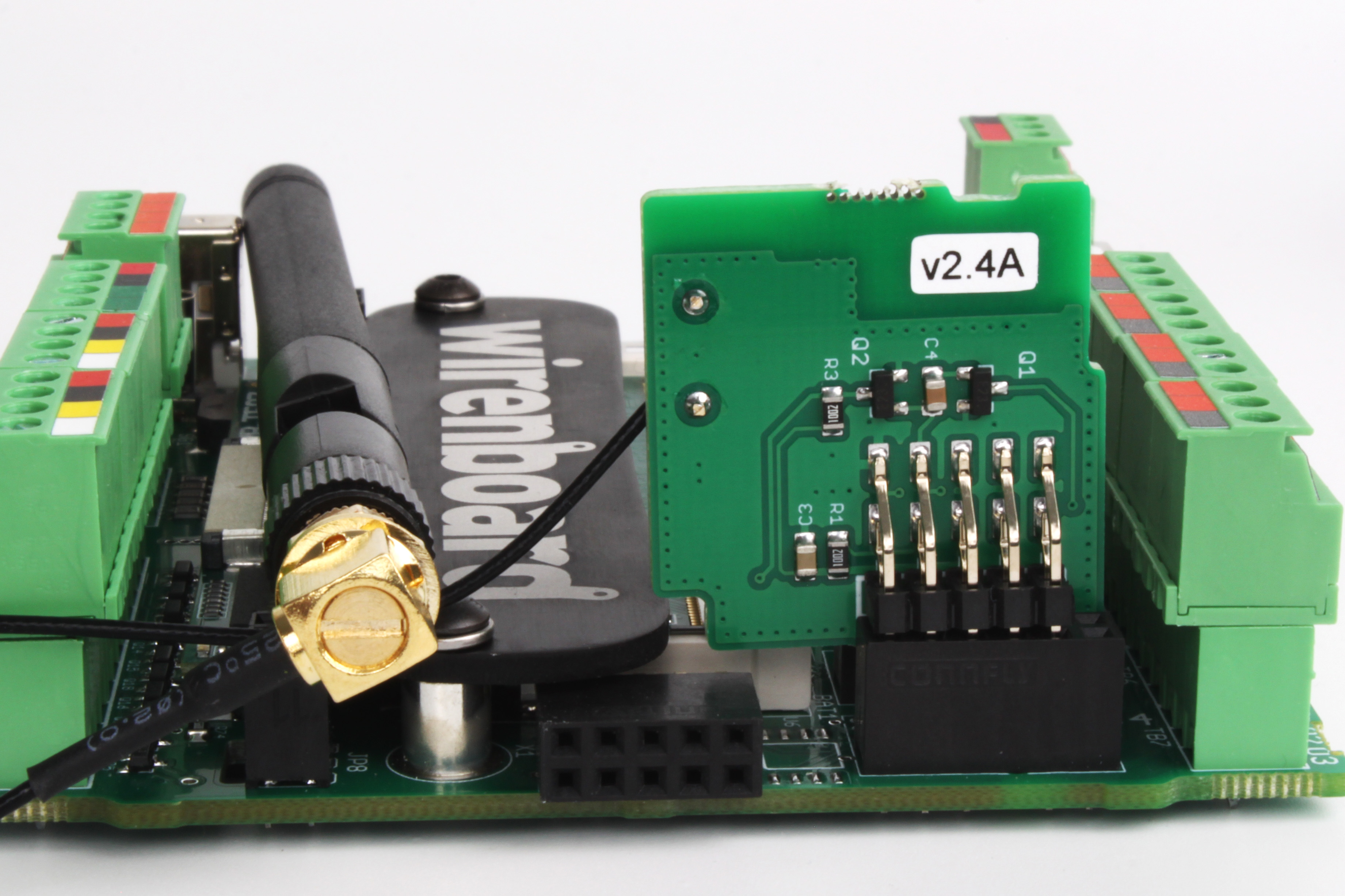 Inserting the module into its connector
-
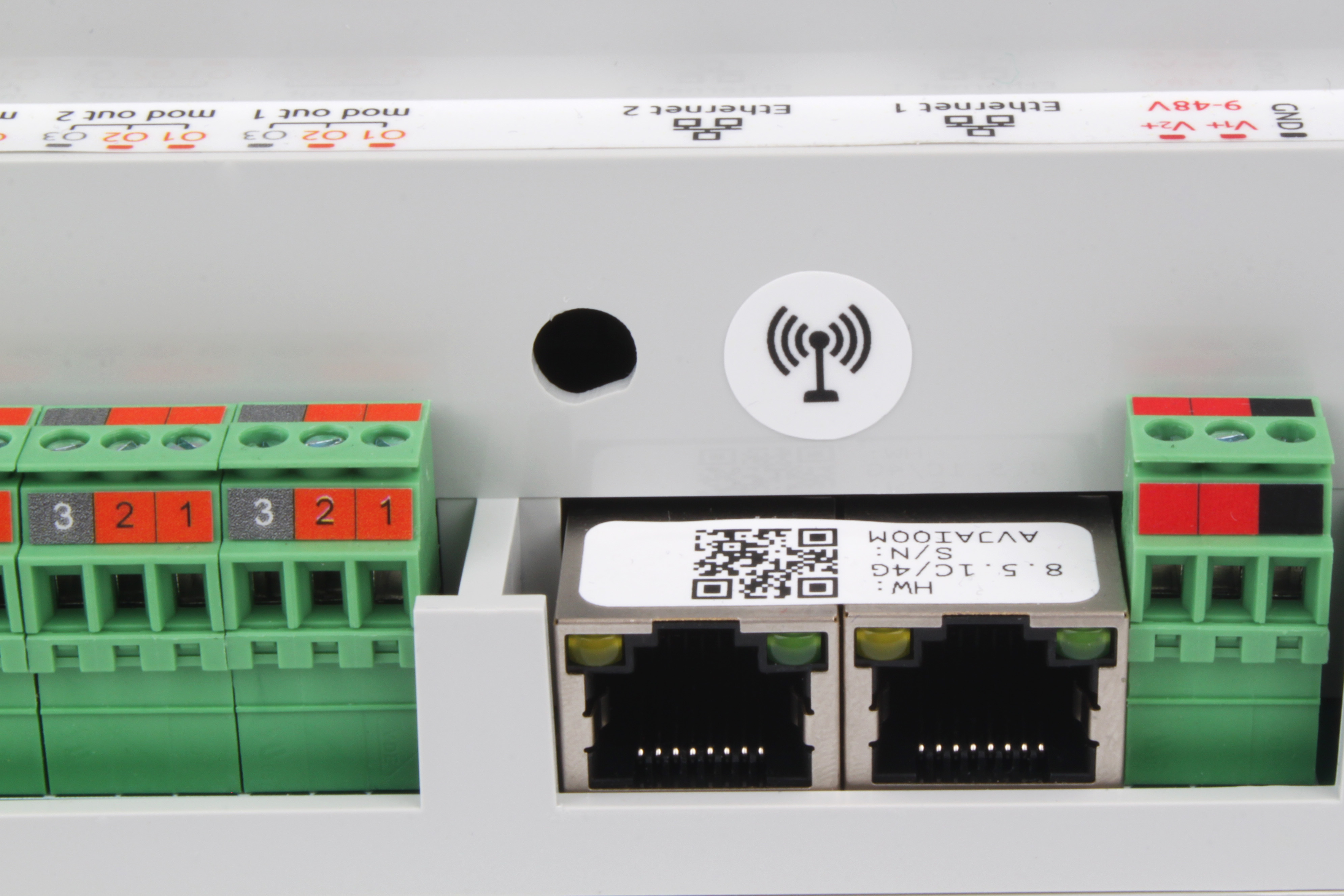 Hole for the SMA antenna socket
-
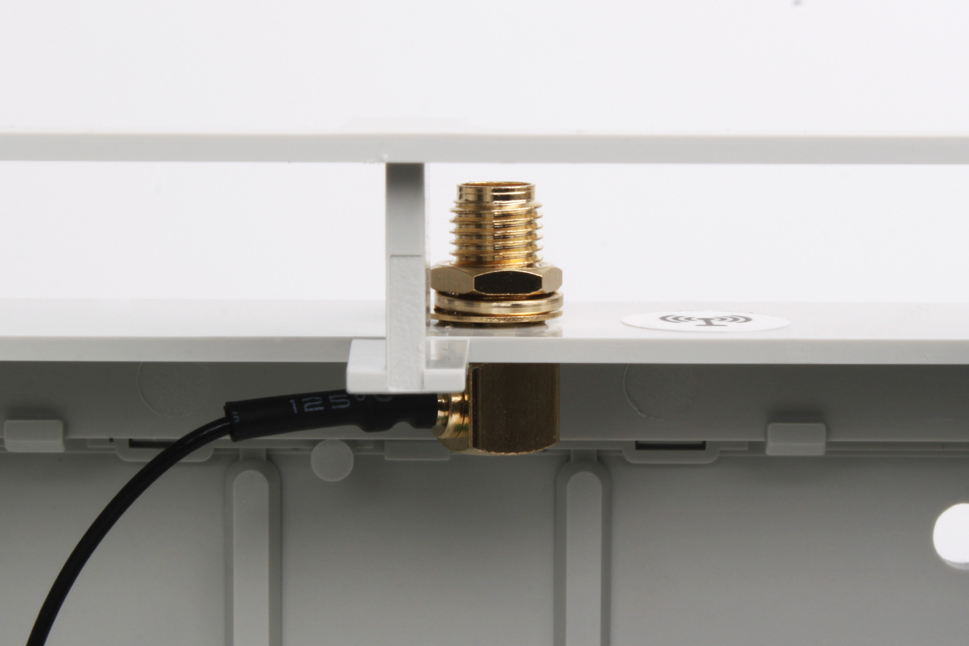 Installing the SMA antenna socket
-
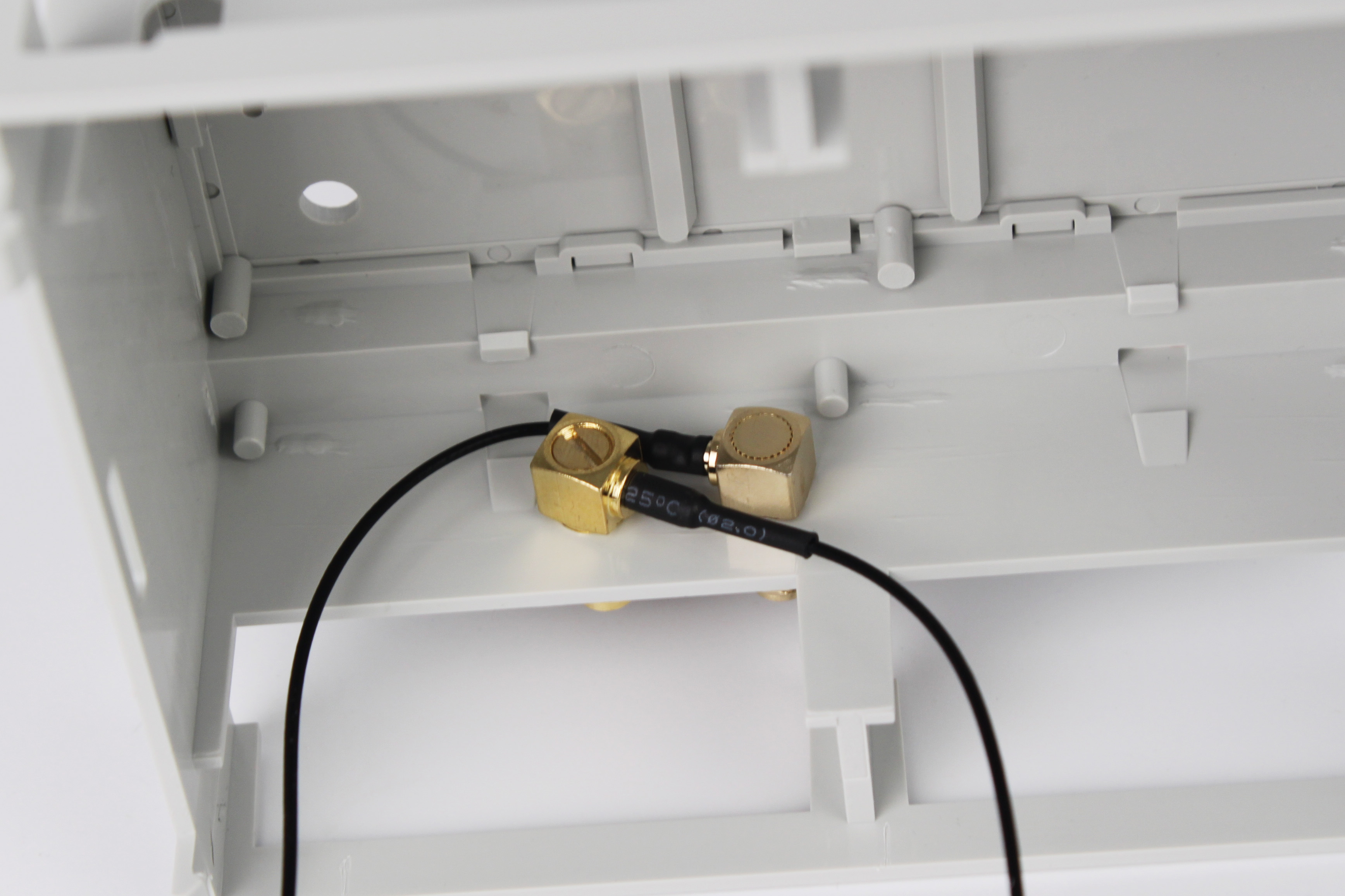 Two right-angle SMA connectors installed in opposite orientations
Configuration
Access permissions
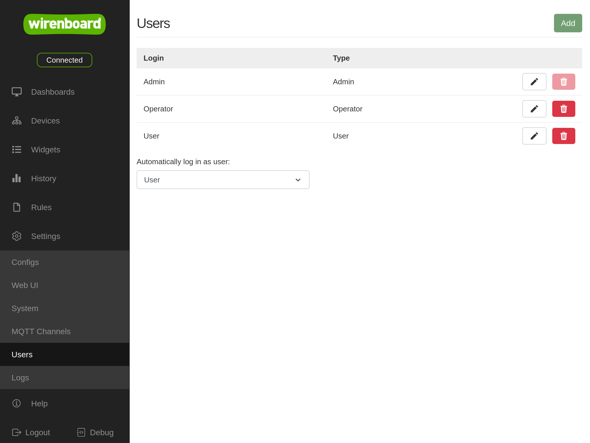
The access level depends on the user account. Users authenticate with a username and password. To change the controller settings, your account must have the following access level: Admin. User accounts are managed under Settings → Users.
Releases earlier than wb-2602 do not have user accounts; configure the access level under Settings → Permissions.
Configuration
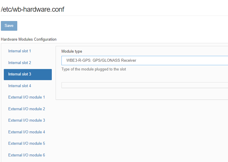
After physically connecting the module, add it to the controller configuration:
- In the web interface, open Settings → Configs → Expansion modules and ports and select the Internal slot in which the expansion module is installed.
- In the Module type list, select the name of the installed module.
- Click Save. The controller will enable the ports required by the module.
To remove a module from the configuration, select Not installed.
For WBE2R-R-ZWAVE-ZWAY, set Module type to Expose UART Pins (DIY).
Controller integration
Communication with the module uses a serial port whose name depends on the connector containing the module.
Configure the Z-Wave network with the controller's Z-Wave software and the serial port listed below.
| Expansion module | Serial port |
|---|---|
| MOD1 | /dev/ttyMOD1 |
| MOD2 | /dev/ttyMOD2 |
| MOD3 | /dev/ttyMOD3 |
| MOD4 | /dev/ttyMOD4 |
Hardware revisions
The batch number (Batch No.) is shown on a label on the side of the enclosure or on the printed circuit board.
| Revision | Batches | Production period | Changes from the previous revision |
|---|---|---|---|
| 3.4 | v3.4A, v3.4B - ... | 02.2026 - ... |
|
| 3.3 | v3.3B, v3.3C - ... | 01.2025 - ... |
|
| 3.3 | v3.3A | 11.2024 - 12.2024 |
|
| 1.x | 03.2022 | Internal test version |