 Documentation
Connecting open-collector outputs
Introduction
An open-collector output is a transistor whose collector is not connected to other internal circuits, while its emitter is connected to the common rail. The transistor operates as a switch controlled by the preceding circuit. The off state (cutoff) corresponds to logic 1; the on state (saturation) corresponds to logic 0.
An open-collector output can increase the allowable digital-output current and directly switch a low-power load. An external resistor pulls the output up to an external supply, allowing devices with different operating-voltage levels to communicate.
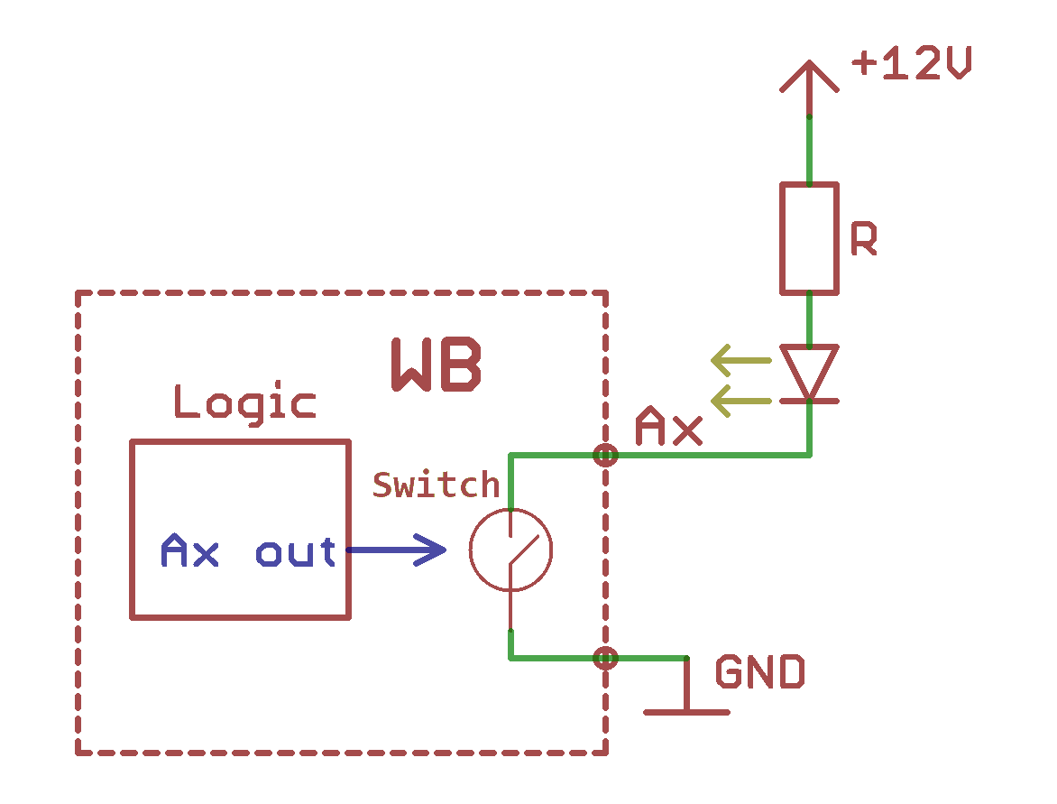
Connection rules
To generate a signal, connect the open-collector output to a supply through an external pull-up resistor, typically several hundred ohms. Select the resistance for the required switching speed and power consumption. Lower resistance increases speed and power consumption.
Paralleling open-collector outputs to control a higher-power load. The transistor's off-state resistance is high but not infinite, so a small leakage current still flows.
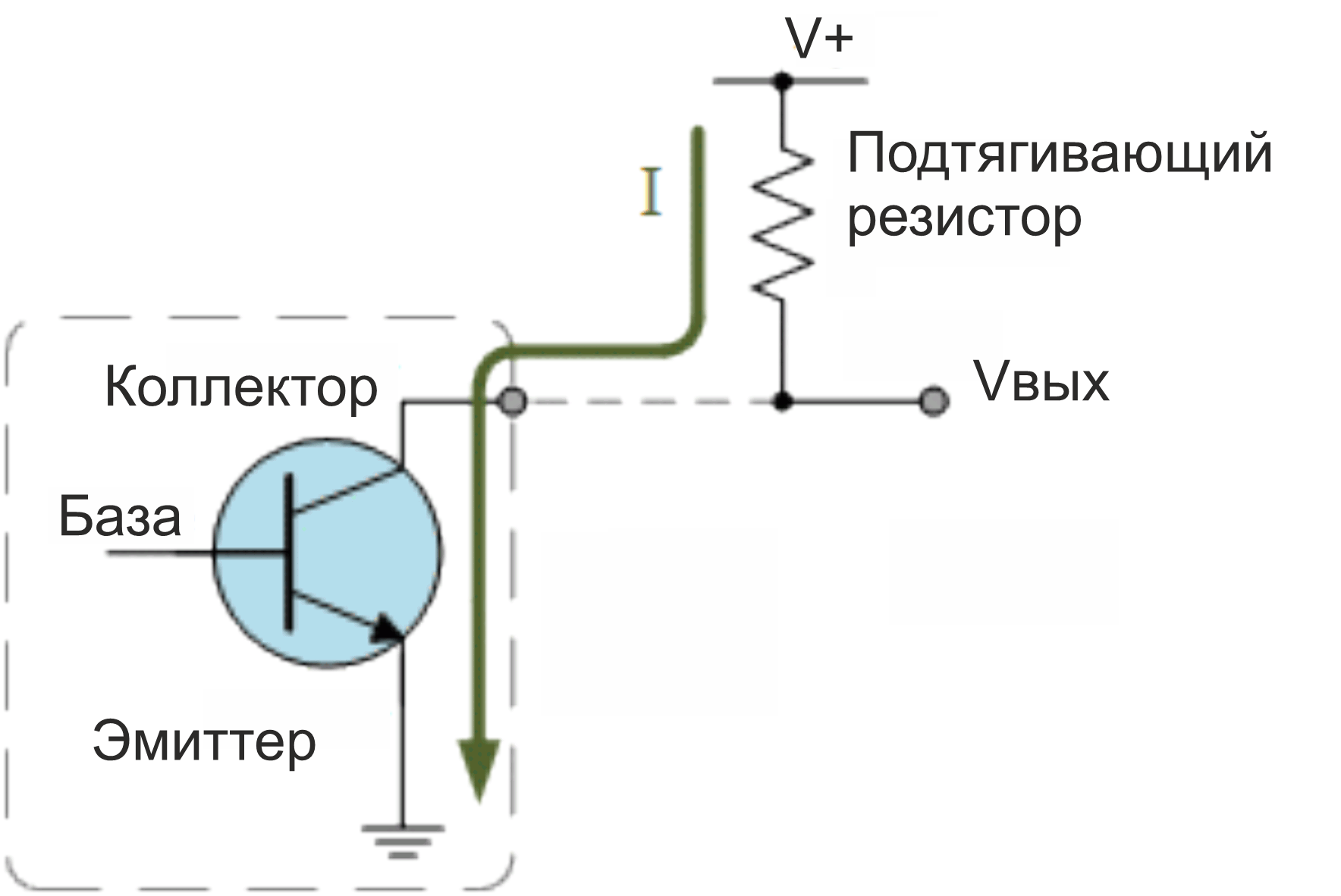
Connecting to a Wiren Board controller
Three connection methods are available:
- WBIO-DI-WD-14, 14 channels: connect the open-collector output to a Dx terminal and the device ground to the module's iGND.
- WBE2-DI-DR-3, 3 channels: connect the output to the Ox terminal corresponding to the expansion module and the device ground to the controller GND.
- Controller Ax (D1): add an external pull-up resistor of approximately 10 kΩ between 5Vout and the corresponding Ax terminal. Join the device and controller grounds.
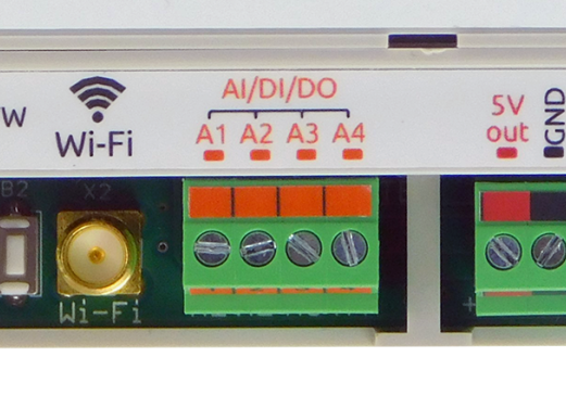
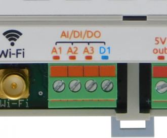
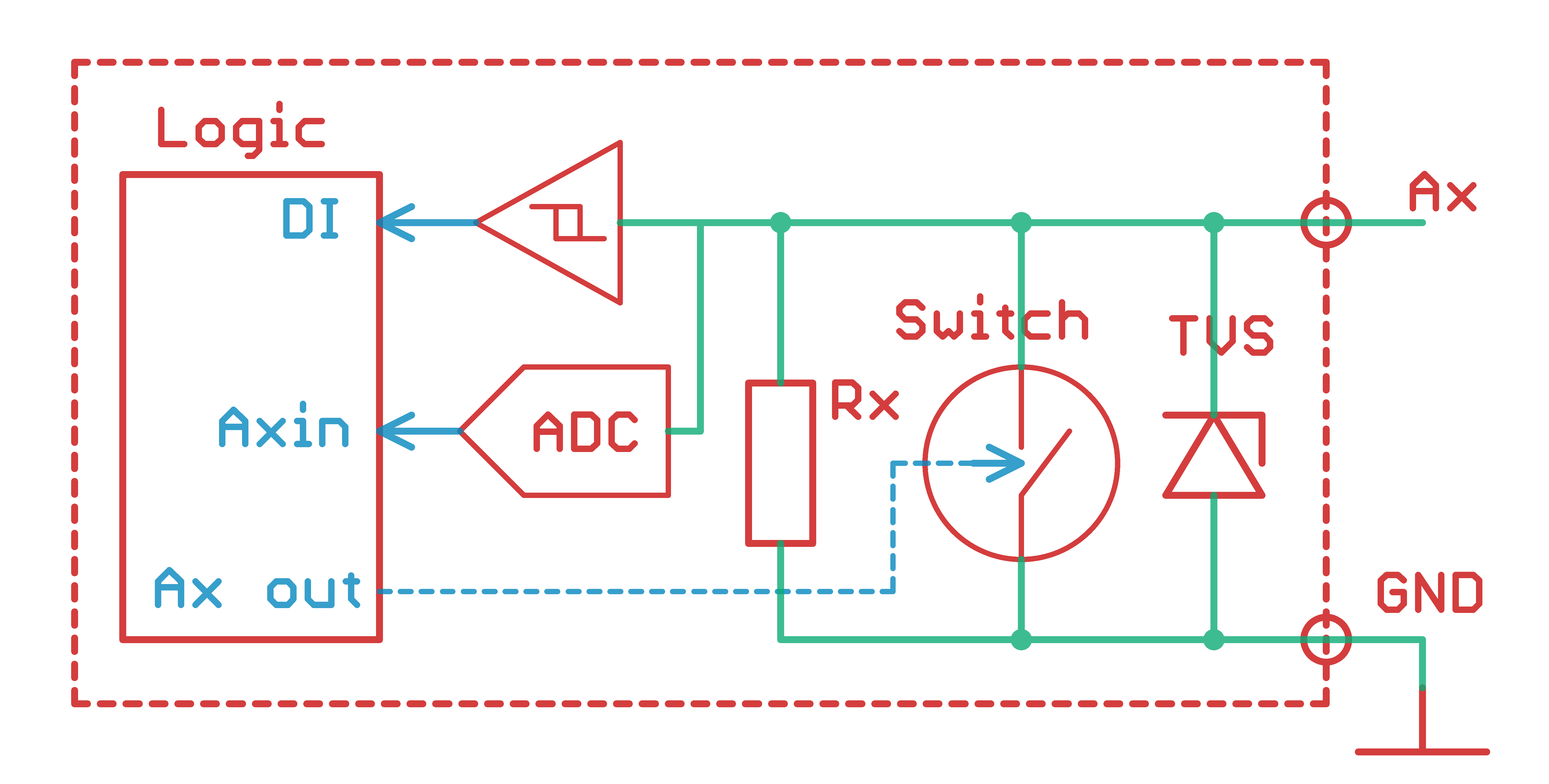
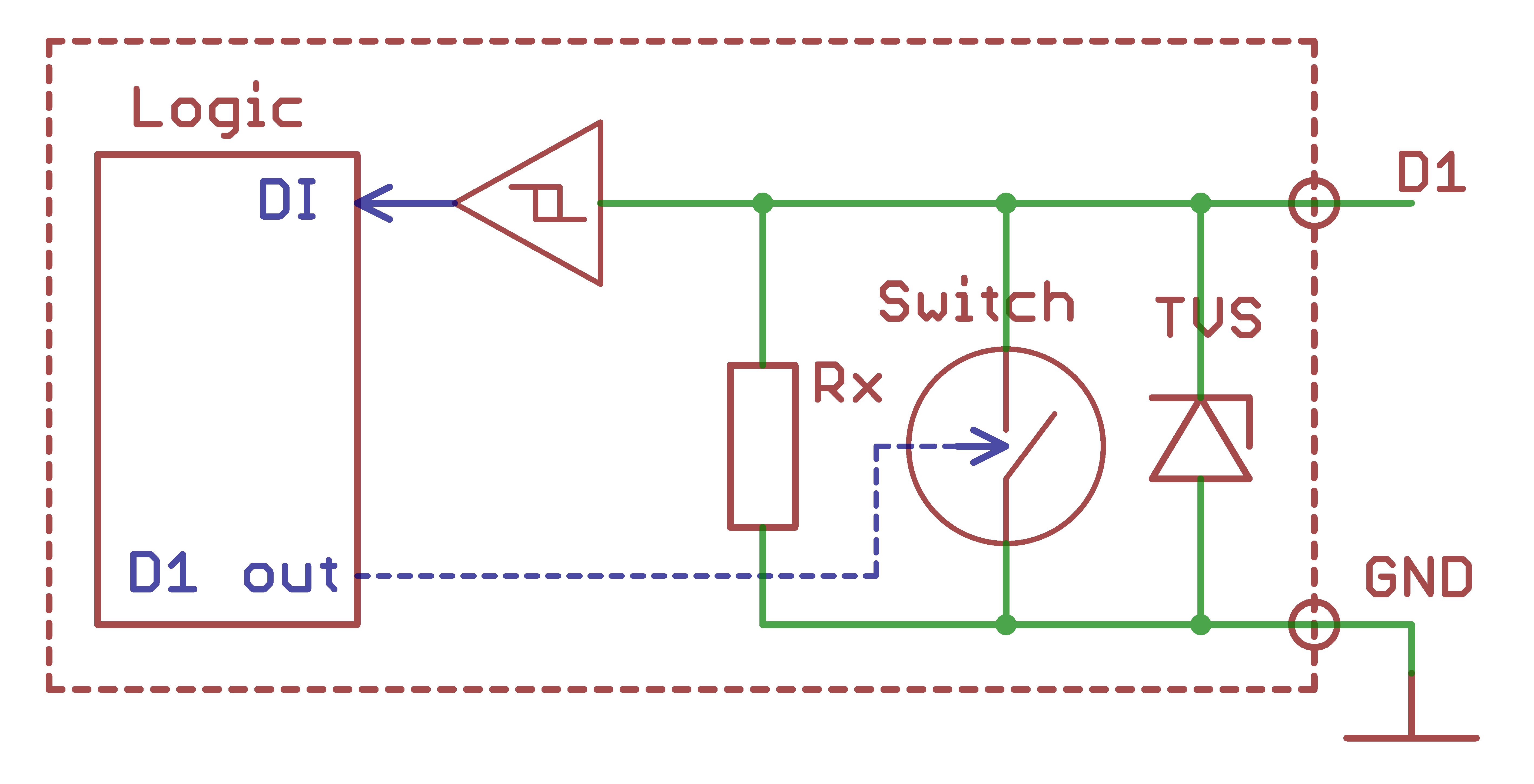
Example: WBIO-DI-WD-14
Other Wiren Board digital-input modules are connected similarly.
- Connect the device ground to iGND and the open-collector output to Dx. The module inputs are galvanically isolated from the controller, so the connected device and controller may have separate grounds.
- Apply power, start the controller and open its web interface.
- Add the module to the controller configuration.
- Check that the external module appears in the web interface.
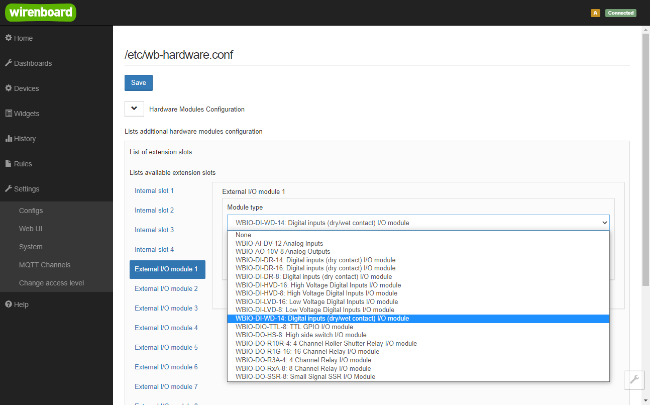
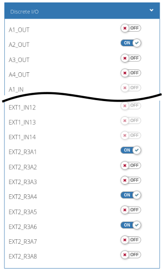
Web-interface controls
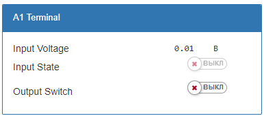
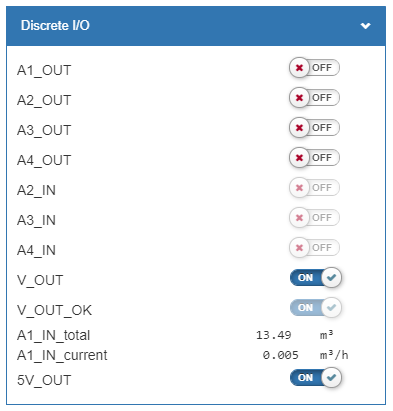
For the internal three-channel module, follow the WBE2-DI-DR-3 installation and configuration instructions.