Documentation
WBC2-4G
4G LTE cellular modem module for Wiren Board controllers
Covered order codes (1)
WBC2-4G— 4G / 3G / 2G modem for Wiren Board 7.4 and 8-series controllers
Overview
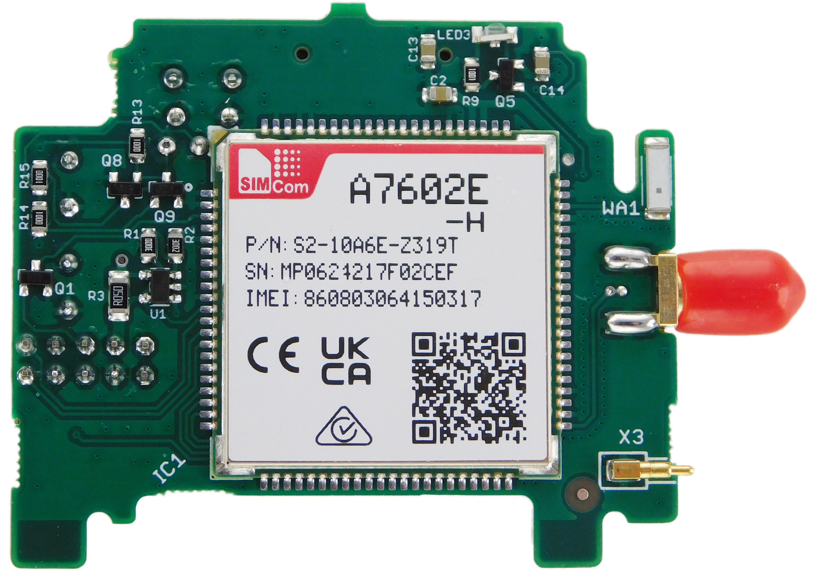
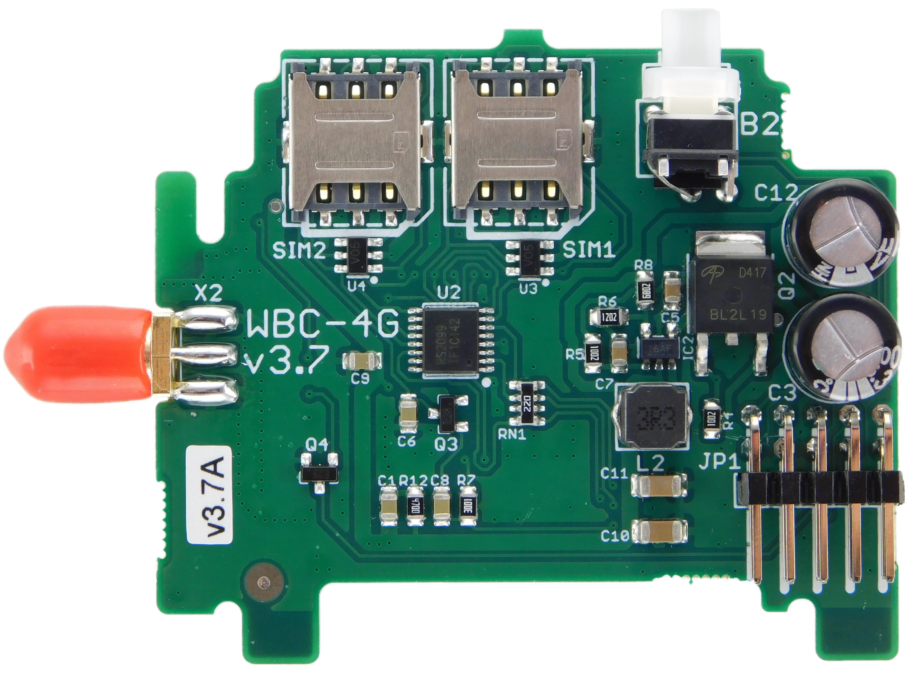
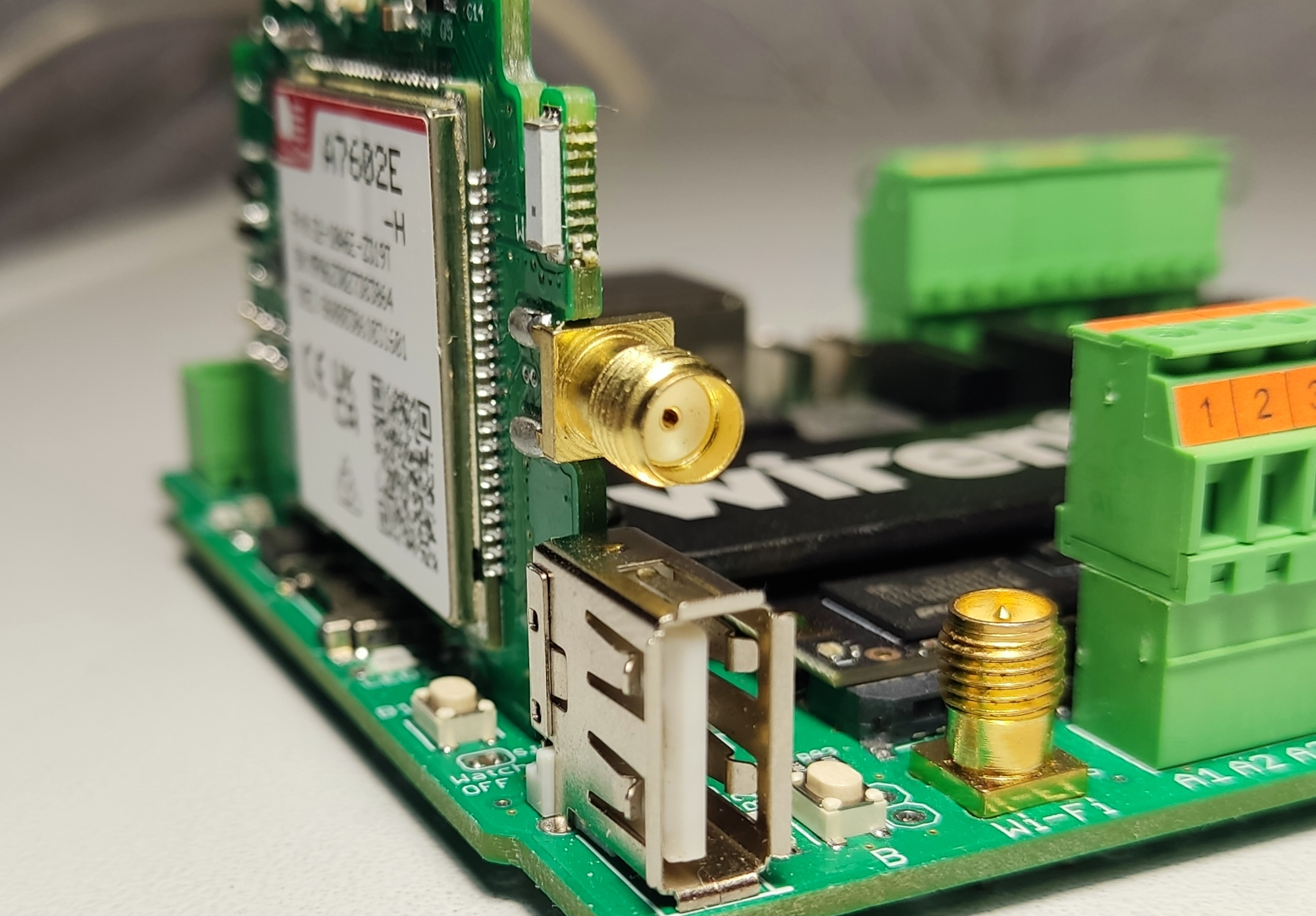
WBC2-4G is a cellular modem for Wiren Board 7.4 and Wiren Board 8-series controllers. It supports 4G, 3G and 2G networks.
The module is not compatible with Wiren Board 6.7–6.9 or 7.2–7.3 controllers. Those controller versions require the WBC-4G v.2 module.
| Parameter | Value |
|---|---|
| Operating frequency bands | LTE-FDD B1, B3, B5, B7, B8, B20 LTE-TDD B38, B40 UMTS/HSPA 900/2100 MHz (B1, B8) GSM/GPRS/EDGE 900/1800 MHz |
| Data rates | FDD-LTE Cat 4: up to 150 Mbit/s download, up to 50 Mbit/s upload TDD-LTE Cat 4: up to 130 Mbit/s download, up to 35 Mbit/s upload HSPA+: up to 42 Mbit/s download, up to 5.76 Mbit/s upload WCDMA: up to 384 kbit/s download and upload EDGE: up to 236.8 kbit/s download GPRS: up to 85.6 kbit/s download and upload |
| SMS | Supported |
| Voice calls | Not supported |
| SIM cards | Two nano-SIM cards |
| SIM operating mode | Alternating |
| Antenna connector | SMA |
| Supply voltage | 5 V |
| Power consumption | Registered on the network: 0.1 W Average during data transmission: up to 3 W Peak: up to 5 W |
Warranty and service life
| Parameter | Value |
|---|---|
| Warranty period | 2 years |
| Service life | 8 years |
Status indication
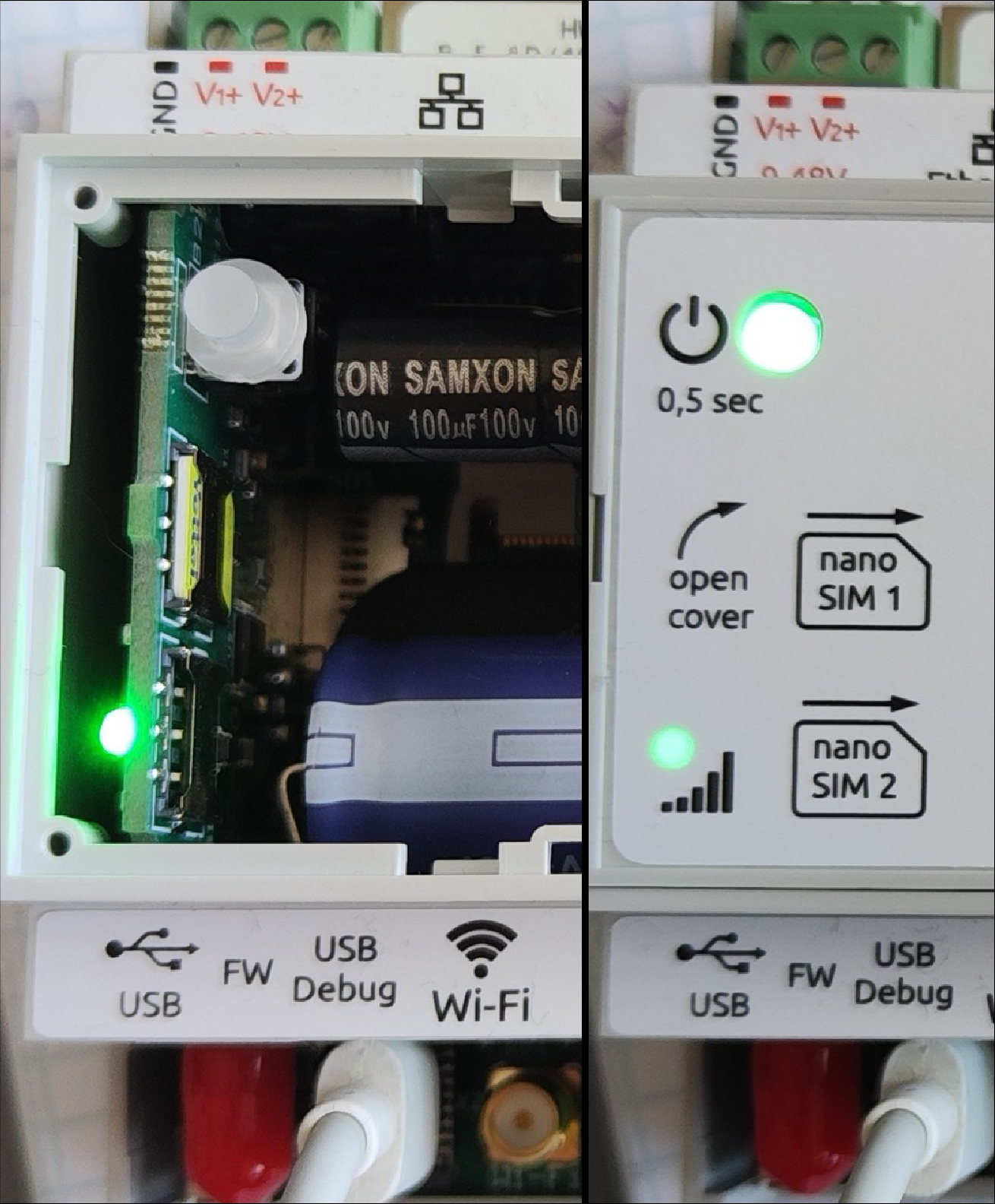
The modem indicator is located under the label on the controller cover.
| Indicator state | Description |
|---|---|
| Continuously on | Searching for a network or an active voice call |
| Flashes every 200 ms | Registered on a 4G network |
| Flashes every 800 ms | Registered on a 2G or 3G network |
| Off | Modem power is off or the modem is in sleep mode |
Installing the module
When expansion modules are ordered together with a Wiren Board controller, they are installed at the factory and configured in the controller web interface.
To install a separately purchased module:
- Disassemble the controller enclosure.
- Install the module with the correct orientation: the protrusion on the module must fit into the slot on the controller board.
- Insert a nano-SIM card.
- Reassemble the controller enclosure.
- Connect an external antenna to the SMA socket. When the controller is installed in a metal enclosure, place the antenna outside the enclosure to ensure reliable radio communication.
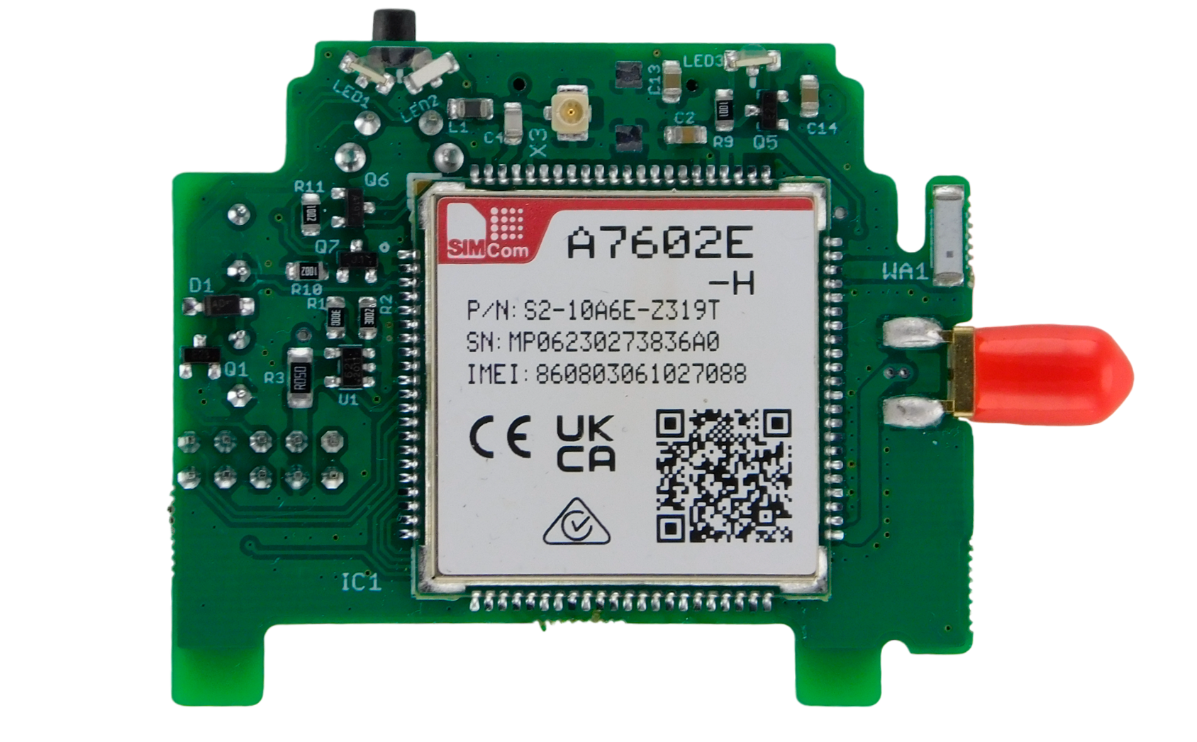
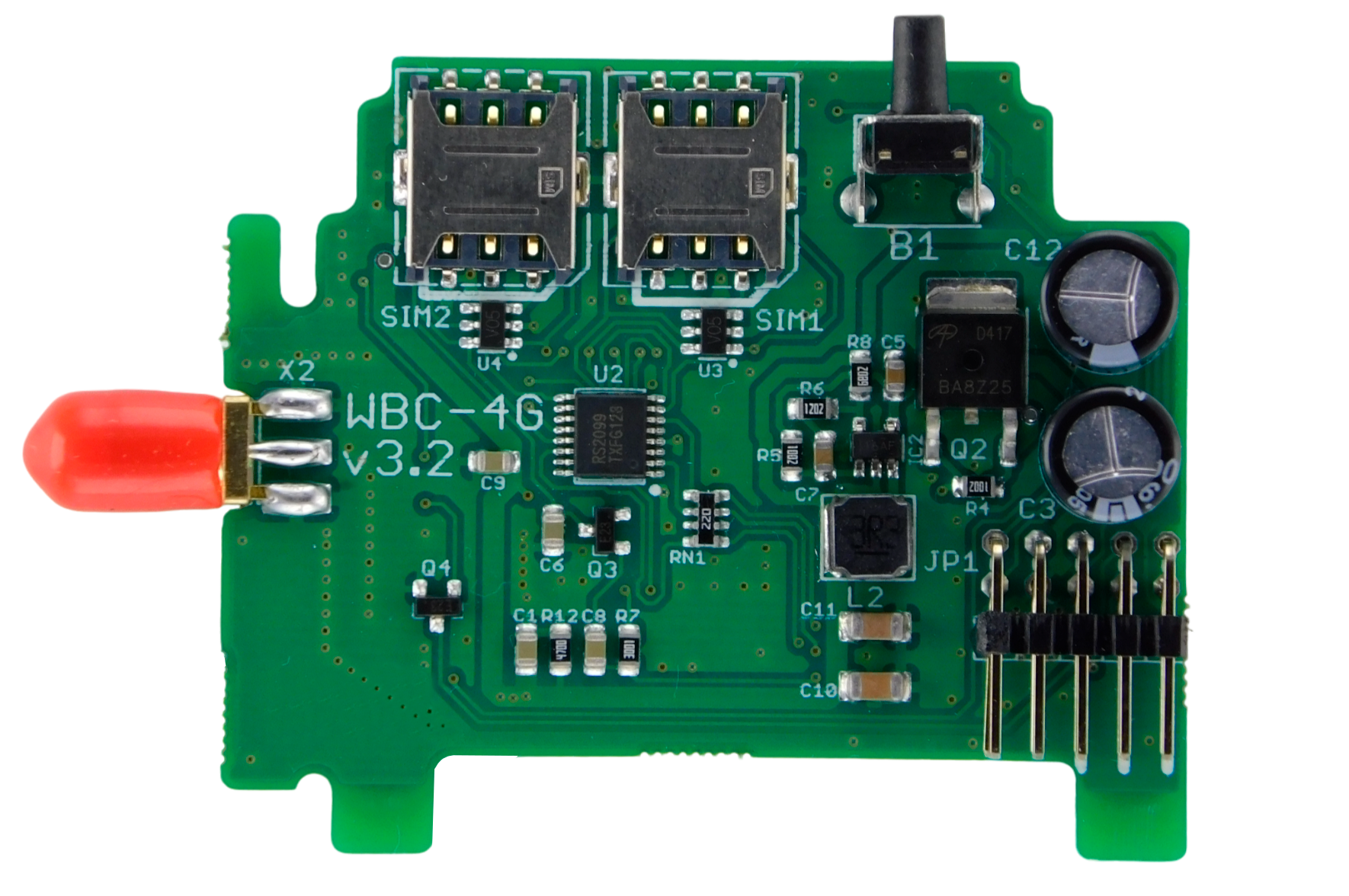
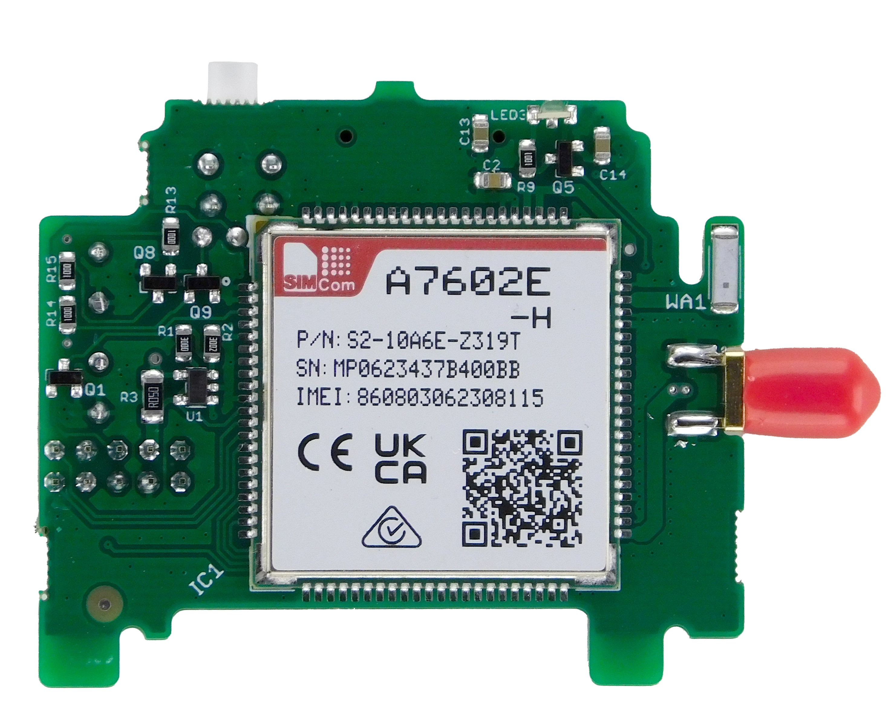
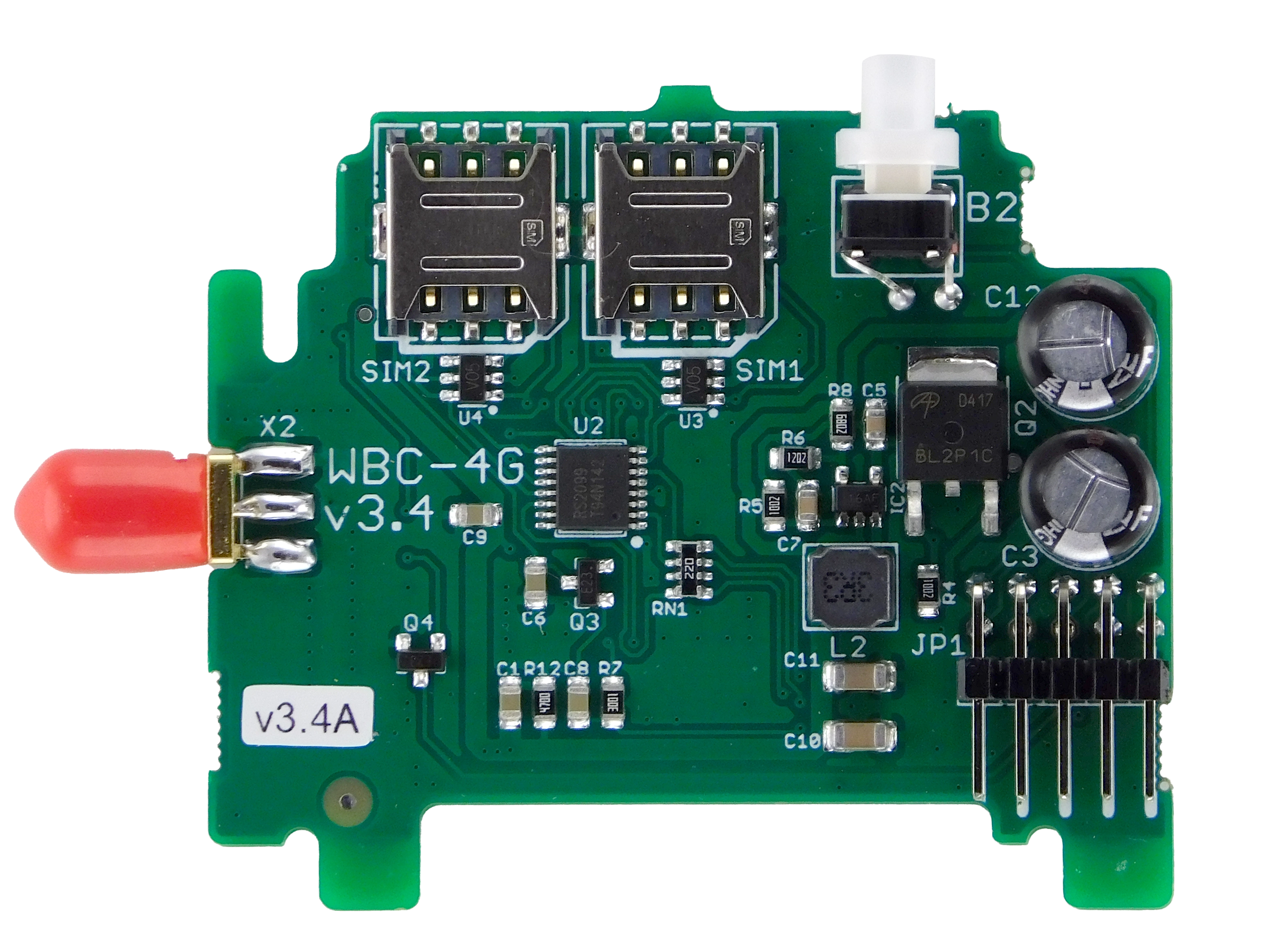
The module exists in two enclosure configurations: one with a separate controller status indicator and another with the indicator integrated into the button. Each configuration requires the corresponding controller top cover.
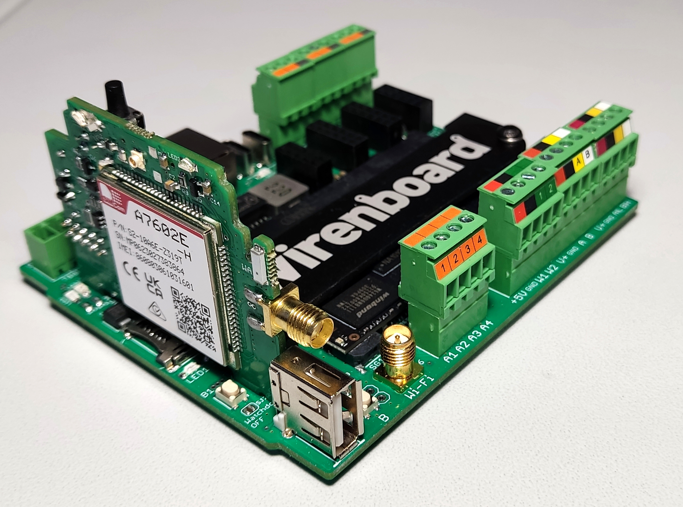
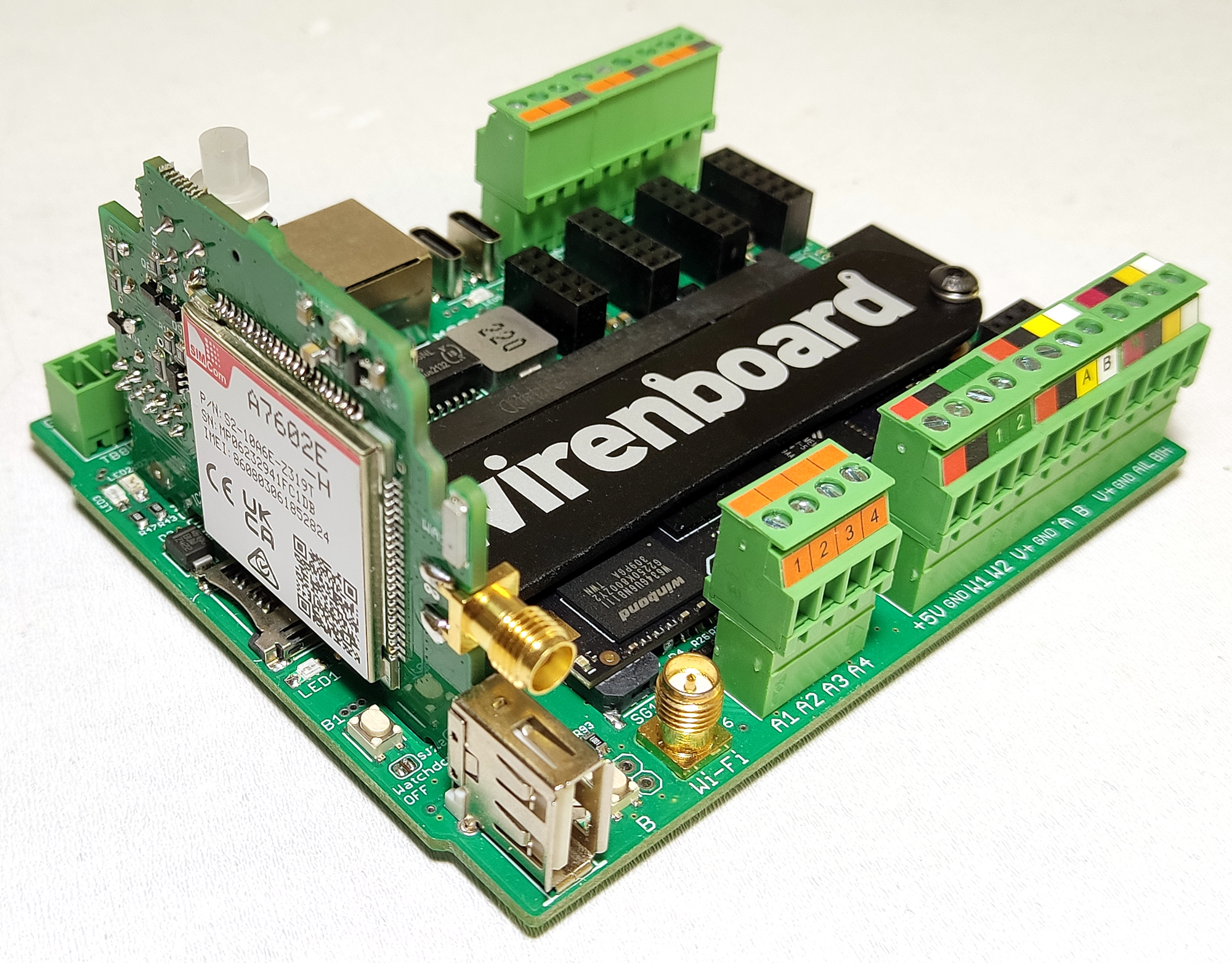
Configuration
After physically installing the modem, add it to the controller configuration:
- In the controller web interface, open Settings → Configs → Expansion modules and ports, then select Modem slot.
- In the Module type list, select the installed module.
- Select Save. The controller enables the ports required by the modem.
To remove the module from the configuration, select Not installed. After configuring the module, configure the cellular internet connection.
Configuring the internet connection
Configure the controller's cellular connection using its 4G modem settings. Because 4G coverage is not available in every region, check the current network-mode setting with AT+CNMP?. To enable automatic network-type selection, send AT+CNMP=2.
Serial interface
The controller communicates with the module through the /dev/ttyGSM and /dev/ttyUSBx serial ports. The USB ports are normally /dev/ttyUSB0 and /dev/ttyUSB1.
Default connection parameters
| Value | Parameter | Description |
|---|---|---|
| Auto-bauding | Baud rate | Set the connection program to 115200 bit/s. After connecting, send AAAAAAAT; the modem will detect the baud rate automatically. |
| 8 | Data bits | Number of data bits |
| None | Parity | Parity bit |
| 1 | Stop bits | Number of stop bits |
| Off | Hardware flow control | Hardware data-flow control |
| Off | Software flow control | Software data-flow control |
The connection parameters can be changed with AT commands when required.
Modem documentation
The modem is based on the SIMCom A76xxE-H family. The following manufacturer documents apply:
- A76XX Series AT Command Manual V1.08
- A76XX Series Dual SIM Application Note V1.02
- A76XX Series Enhance Sleep Mode Application Note V1.00
- A76XX Series JD Application Note V1.00
- A76XX Series LBS Application Note V1.03
- A76XX Series Linux USB Application Note V1.03
- A76XX Series Sleep Mode Application Note V1.03
Known issues
Before commissioning, check whether the hardware revision used in the installation has any known limitations. Identify the revision from the batch number printed on the side label or on the PCB.
Hardware revisions
The batch number is printed on a label on the side of the enclosure or directly on the PCB.
| Revision | Batches | Production dates | Changes from the previous revision |
|---|---|---|---|
| 3.9 | v3.9A, v3.9B, v3.9C, v3.9C/1 and later | April 2026 onward | PCB layout changes to improve noise immunity |
| 3.7 | v3.7A, v3.7A/1, v3.7B, v3.7C, v3.7D, v3.7E, v3.7E/1 and later | August 2024 – March 2026 | Improved noise immunity by adding a pogo-pin USB contact; minor PCB layout changes |
| 3.4 | v3.4A, v3.4A/1, v3.4B, v3.4C, v3.4C/1 through v3.4C/6, v3.4D, v3.4D/1 | February – July 2024 | New illuminated button; GNSS support removed; minor internal changes |
| 3.2 | v3.2A, v3.2B, v3.2C, v3.2C/1 | July 2023 – January 2024 | Switch replaced with a button; minor internal changes |
Troubleshooting
Interference from relays and contactors
Relays and contactors can generate interference that affects nearby devices. When switching loads—especially inductive loads—the contacts can produce high-frequency transients with amplitudes of several kilovolts. These transients may couple into other circuits. Install suitable snubber circuits across the switched load to suppress voltage spikes and improve system stability.
Device images and drawings