 Documentation
WB-MGE v.3
RS-485, Ethernet, Wi-Fi and WBIO gateway
Covered order codes (1)
WB-MGE v.3— Model designation; SmartSD does not list a separate SKU
This page describes the new device WB-MGE v.3; for the previous version, see WB-MGE v.2.
This page describes the latest hardware revision with the latest stable firmware. If your device runs older firmware, update it where possible (see Firmware update).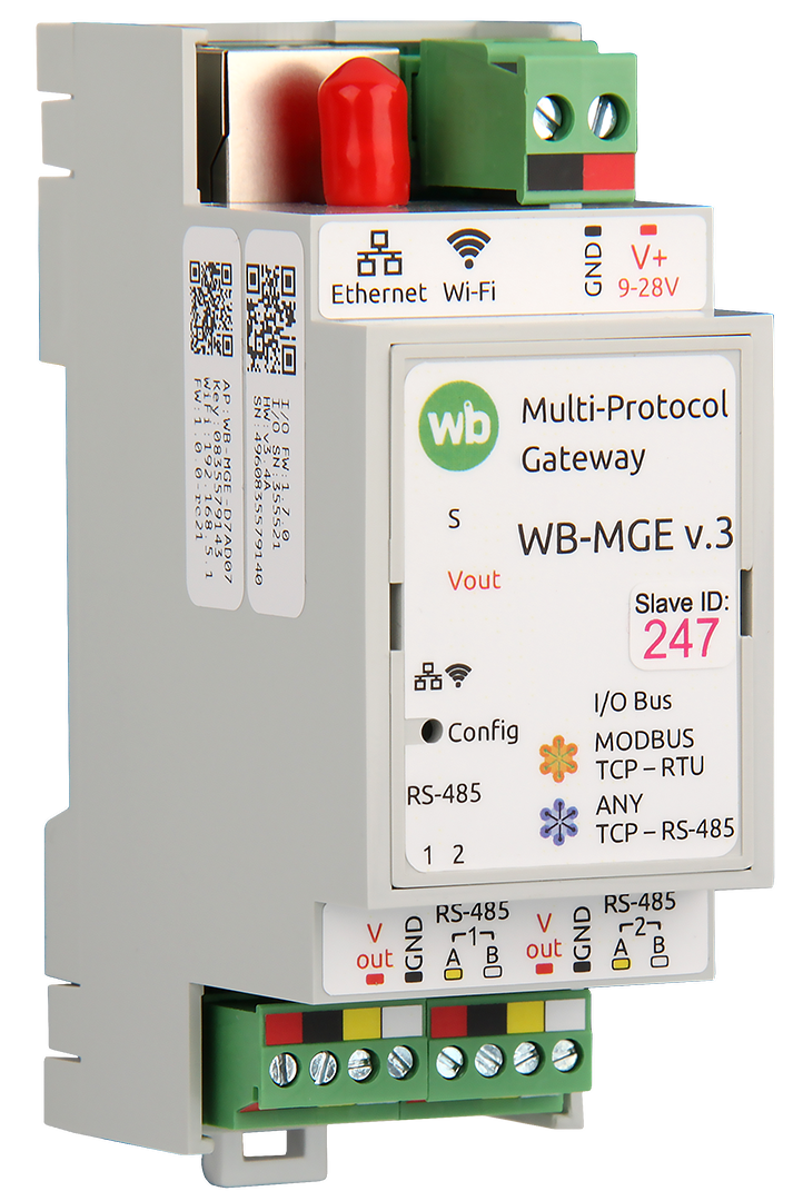
Purpose
Designed for connecting devices with an RS-485 interface and WBIO side input/output modules to an automation server via Ethernet or Wi-Fi. The server can be a Wiren Board controller or any controller / computer supporting the required protocols.
Two WB-MGE v.3 units can be used to set up a bridge over Ethernet or Wi-Fi. This is useful when a third-party controller has no network interfaces but a remote RS-485 segment has to be polled.
Each port is assigned a mode: «Modbus TCP», «Transparent bridge» or «Passive». On top of any mode, overlays can be enabled independently — a sniffer of Modbus traffic and a caching multimaster (a Modbus TCP server serving values from the cache). Both ports together can work as a repeater — a transparent RS-485 relay between Port 1 and Port 2.
The device is flashed and ready to use as a gateway. The firmware is open source (MIT-WB license), sources: github.com/wirenboard/wb-mge. You can add any functionality you need for your own tasks or write your own firmware. Read more about developing DIY firmware.
Changes from the previous version
Differences between WB-MGE v.3 and WB-MGE v.2:
- a modern multilingual web interface (Russian, English, German, Italian and Kazakh), usable on a computer or mobile phone;
- 2 RS-485 ports that can use any protocols on each port;
- Wi-Fi in addition to Ethernet, which can be disabled when not needed — including permanently (important for projects that prohibit wireless communication);
- optional PoE 802.3af/802.3at through the WBP-ACTIVE-POE module, with the ability to power devices connected to WB-MGE v.3;
- support for WBIO side input/output modules;
- electronic control of termination and fail-safe biasing;
- power control for connected devices;
- Factory mode to restore operation if the main firmware fails;
- a USB-C debug port;
- a Modbus traffic sniffer with decoding directly in the web interface;
- a caching multimaster: the gateway collects bus values and serves them through a separate Modbus TCP server without polling devices again, allowing several masters to read data simultaneously;
- disabling transmission (TX) on a port — the transceiver is physically switched to receive-only mode for a completely non-intrusive connection to existing systems;
- repeater mode — transparent RS-485 forwarding between the two ports;
- open-source firmware (MIT-WB license);
- developers can use the module hardware with their own firmware.
Technical specifications
| Parameter | Value |
|---|---|
| Power supply | |
| Interface supply voltage | 9–28 V DC |
| Power consumption at 24 V | 1 W |
| Maximum Vout current | 2.5 A |
| Maximum continuous Vout current when powered by PoE | 500 mA |
| Power inputs |
|
| Power input priority |
the input with the higher voltage |
| Power output for external devices | |
| Vout | The terminals supply the module's input voltage, with overcurrent protection above 2.5 A, software switching and retention of the output state after reboot.
When powered by PoE, Vout supplies a regulated 24 V. The available Vout current is lower when powered by PoE. |
| Terminal blocks and wire cross-sections | |
| Recommended wire cross-section with insulated wire-end ferrules | 0.35–1 mm2 — single ferrule; 0.35–0.5 mm2 — twin ferrule |
| Standard ferrule sleeve length | 8 mm |
| Screw tightening torque | 0.2 N·m |
| Communication | |
| Communication protocol |
Ethernet or Wi-Fi: Modbus TCP, or a transparent TCP connection carrying serial data. RS-485 terminals: Modbus RTU in Modbus TCP gateway mode; any supported serial protocol in Transparent bridge mode. The gateway converts Modbus TCP to Modbus RTU and back; the transparent bridge forwards serial data unchanged. Side I/O connector: WBIO. |
| Interfaces |
|
| Simultaneous TCP connections per port |
|
| RS-485 interface parameters | Software-configurable; defaults:
9600 bit/s; 8 data bits; no parity (N); 2 stop bits |
| Ready after power-on | 8 s |
| Operating conditions | |
| Ambient air temperature | −40 to +70 °C |
| Relative humidity | Up to 95%, non-condensing |
| Climatic classification under GOST 15150-69 | O2.1* |
| Warranty period | 2 years |
| Service life | 8 years |
| Dimensions | |
| Width, DIN modules | 2 |
| Overall dimensions (L × W × H) | 36 × 90 × 58 mm |
| Weight (including box) | 105 g |
Operating principle
Hardware
The module is based on the ESP32 chip, which implements the functions of an RS-485 gateway, allows controlling peripherals and indicators, and provides a web interface and API for configuring the module.
Network interfaces and packet handling
The module has two network interfaces: Ethernet and Wi-Fi, which can act as an access point or a client.
The module firmware receives packets over Ethernet / Wi-Fi and sends them to one of the RS-485 ports, then relays the device responses back. The port is selected by the TCP port the packet arrived on, by default: 502 — RS485-1, 503 — RS485-2.
Besides pass-through forwarding, two independent tools that work passively with the bus traffic can be enabled on top of any port:
- sniffer — captures and decodes Modbus frames in both directions and shows them in real time in the web interface (diagnosing the exchange without an external analyzer);
- a caching multimaster — collects the latest device register values from the traffic and serves them over a separate Modbus TCP server without re-polling the bus, removing the «one master per line» restriction.
Both are described in detail in the Operating modes section.
WBIO support
To connect WBIO side modules , there is an additional WB-MIO inside, which presents all side modules as a single Modbus device on the RS-485-2 port. Read about addressing and configuration in the configuration section: I/O Bus (WBIO side expansion modules).
Fast Modbus
The specific feature of Fast Modbus is the presence of arbitration packets:
- Transparent mode — we pass the packets through as is;
- Modbus TCP — we handle the arbitration packets separately in the gateway firmware.
As a result, Fast Modbus works in both modes.
Power supply
The module can be powered in two ways: directly from the Vin terminal or, optionally, over PoE conforming to the IEEE 802.3af / 802.3at standards.
Powering over PoE requires a separate WBP-ACTIVE-POE module with a built-in voltage converter, which is installed inside the device. It converts the incoming PoE voltage to 24 V and supplies it to the internal power bus of the gateway.
The WBP-PASSIVE-POE module may be used, but only at a supply voltage no higher than 24 V DC. Exceeding this voltage will damage the gateway.
The module has two power outputs (Vout) for connecting peripheral devices. The outputs are controlled as a group: both channels are switched on and off simultaneously via the web interface. The total load on both outputs must not exceed the value given in the table.
| Connected load power | Vin (24 V) | Active PoE mode | Passive PoE mode | |
|---|---|---|---|---|
| 802.3af | 802.3at | |||
| Nominal | 60 W | 15 W | ||
| Maximum short-term | 120 W | 12 W | 28 W | 30 W |
Indicators
On the front panel, under the label, there are indicators that show the state of the module and its outputs.
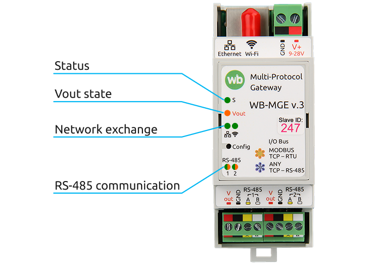
| Designation | Color | State | Value |
|---|---|---|---|
| Status | Green | blinking | the device has booted and is operating normally |
| on | power is present, problem with the firmware | ||
| Vout | Orange | on | device power ON |
| off | device power OFF | ||
| Ethernet | Green | on | link present |
| blinking | data exchange in progress | ||
| off | no link | ||
| Wi-Fi | Green | on | enabled, no data exchange |
| blinking | data exchange in progress | ||
| off | disabled | ||
| RS485 1/2 | Green (RX) | blinking | receiving data from the port |
| Orange (TX) | blinking | sending data to the port |
Installation
The WB-MGE v.3 is mounted on a standard 35 mm wide DIN rail and occupies the width of 2 DIN modules.
Wiring
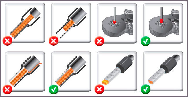
Use flexible stranded wire with insulated wire-end ferrules (NSHVI).
Strip the insulation to the sleeve length, or strip a little more and trim the protruding wire after crimping. Use a ferrule crimping tool. A crimped ferrule protects the strands from the screw clamp and secures the connection.
Do not overtighten the terminal screws: excessive force damages the screw terminal.
Module power supply
The V+ GND terminal block with a 5.08 mm pitch is used to connect the power supply.
The module can also be powered over Ethernet PoE.
Network interfaces
The module is connected to a Wiren Board controller or another device directly over Ethernet or via Wi-Fi, including through a router or a VPN. The main requirement is that the IP address of the module must be reachable from the controller.
RS-485
The V+ GND A B terminal block with a 3.5 mm pitch is used to connect devices over the RS-485 bus. Power for the connected devices can also be taken from these terminals. For a stable connection with a device it is important to wire the RS-485 bus correctly, read about it in the article RS-485 bus wiring and connection.
The RS-485 interfaces are independent, each has individual settings for speed, stop bits and other parameters. The terminator and fail-safe biasing are enabled by default. They can be disabled in the settings. The RS-485 grounds in the WB-MGE v.3 are not isolated from the power ground.
I/O Bus
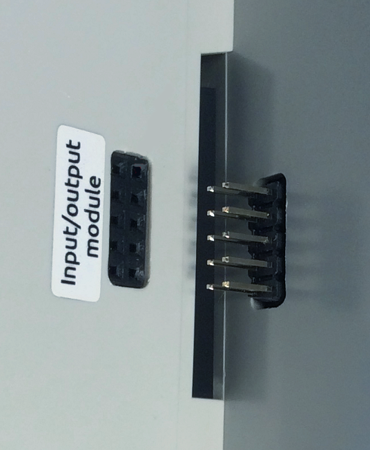
Up to 8 modules can be connected in series: up to 4 input modules (type «I») and up to 4 output modules (type «O»).
WBIO side input/output modules are connected to the I/O Bus port located on the right side of the module. Make sure that all pins of the module fit into the holes of the mating connector.
The device makes it possible to separate the input/output modules from the Wiren Board controller and move them to another DIN rail or another cabinet. In addition, this interface converter allows using the input/output modules as a standalone device with controllers from other manufacturers.
- Connecting devices to the WB-MGE v.3
-
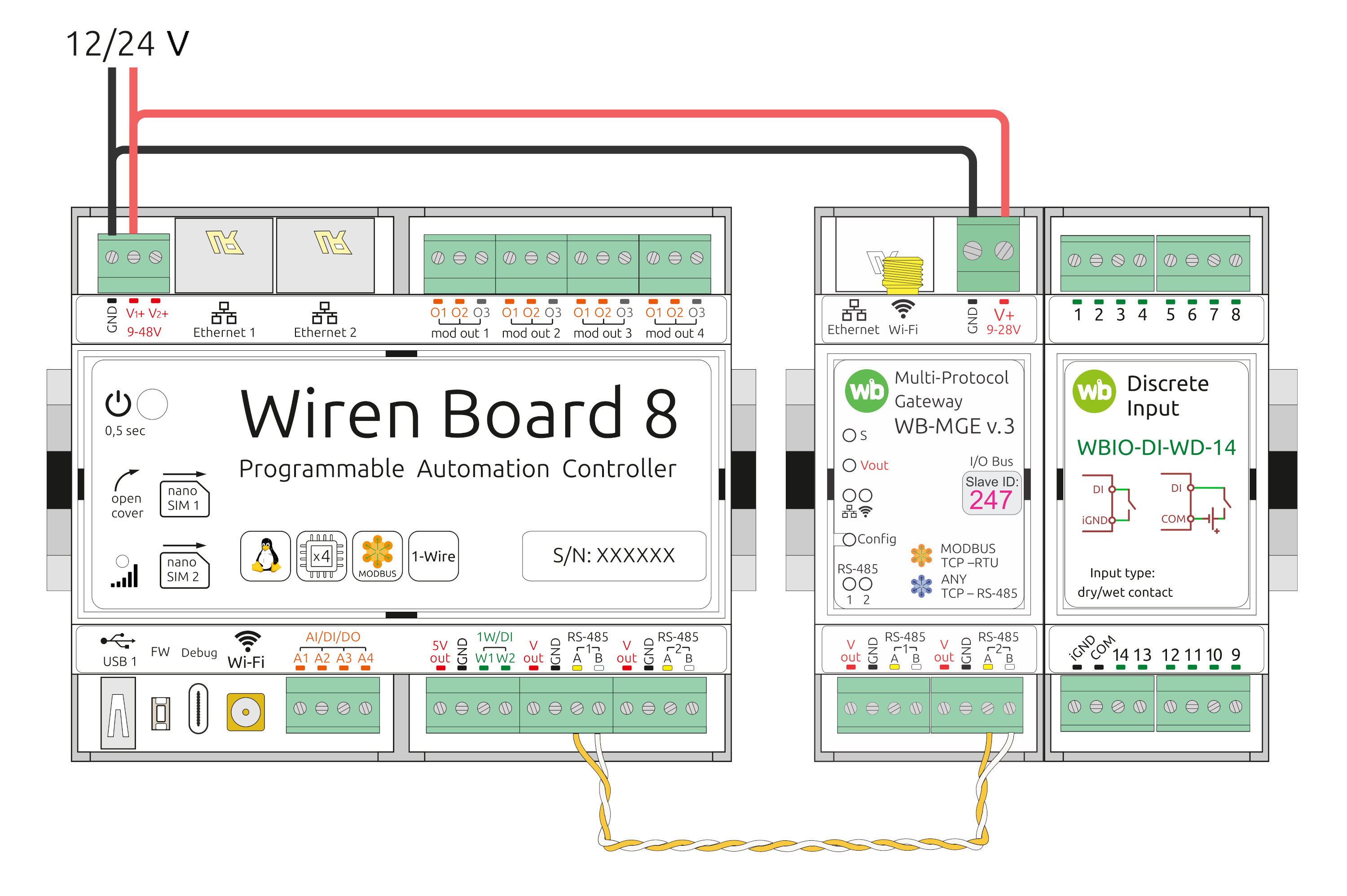 Side modules
-
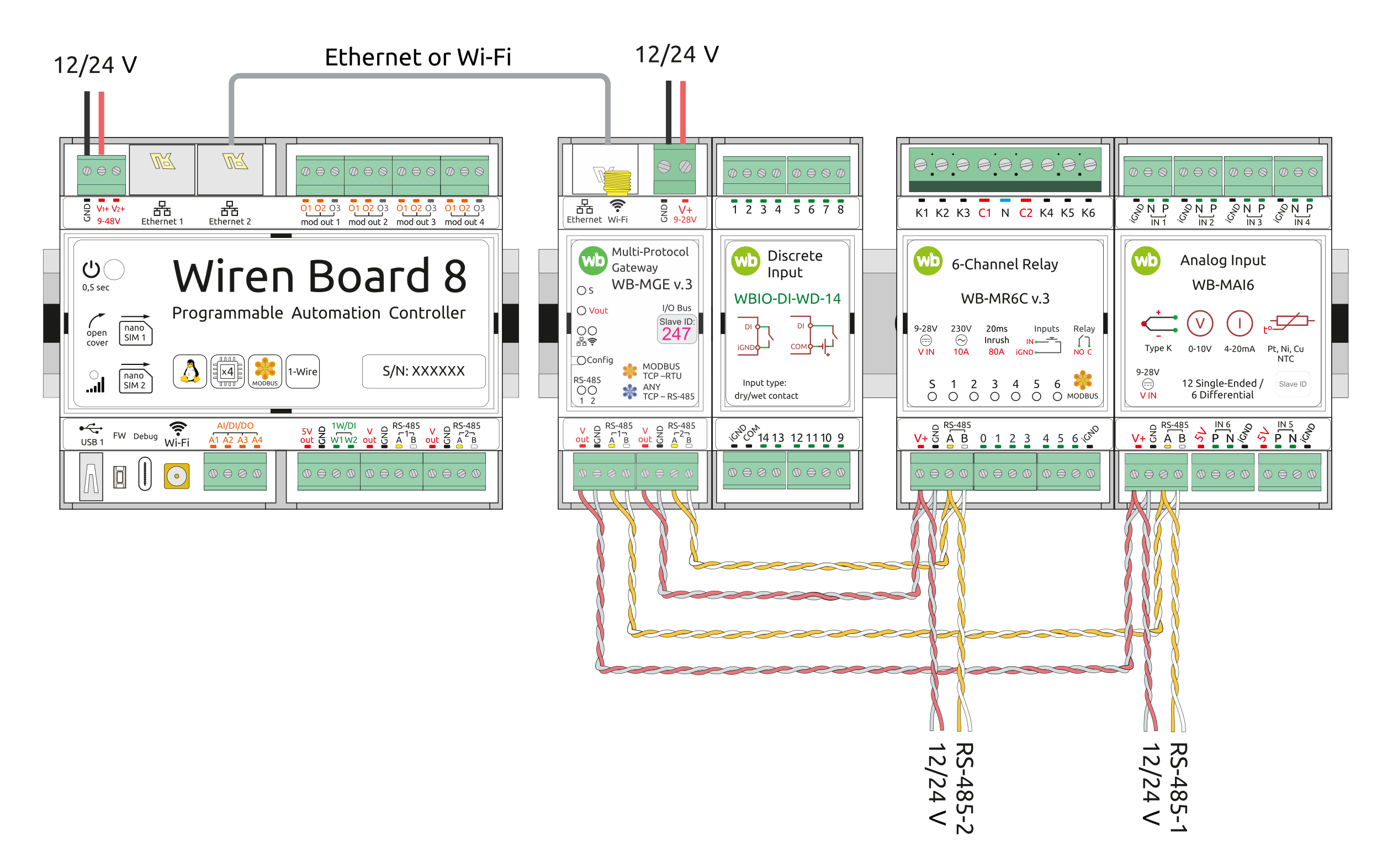 A side module and RS-485 devices at the same time
Operating modes
Modbus TCP mode
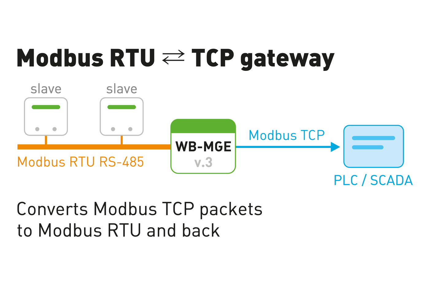
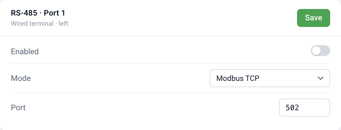
In this mode the module receives Modbus TCP requests over the network interfaces, converts them into Modbus RTU and passes them to one of the RS-485 ports. The received RTU response is converted back into Modbus TCP and returned to the client that sent the request.
The mode is selected for each port separately:
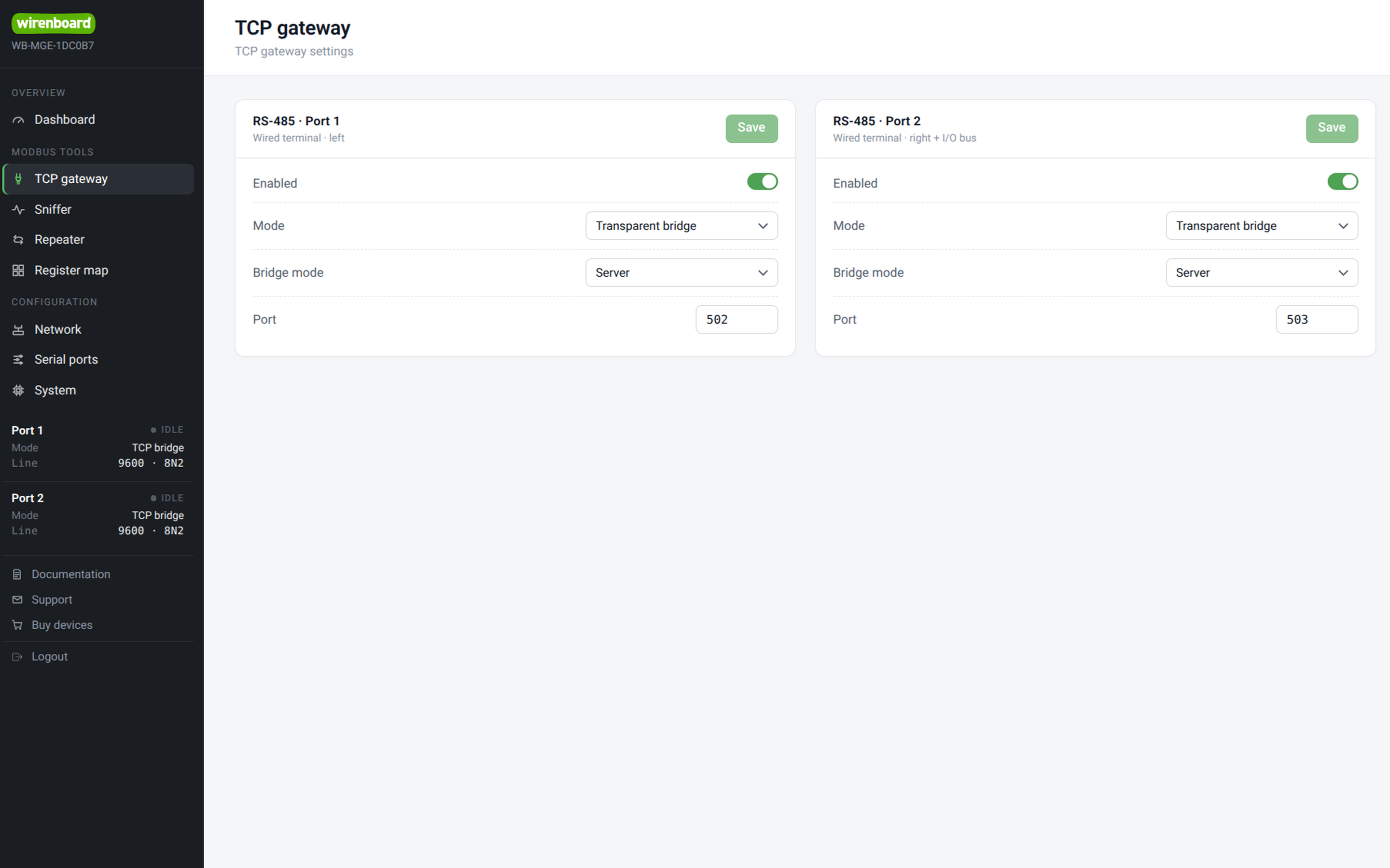
- Go to Modbus Tools → TCP gateway and select the card of the required port.
- In the Mode field select «Modbus TCP».
- If necessary, specify the TCP port whose requests will be forwarded to this RS-485 port. By default: 502 — RS-485-1, 503 — RS-485-2.
In Modbus TCP mode the module works only as a server. Several TCP clients (up to 8) can be connected to each port at the same time.
Transparent bridge mode
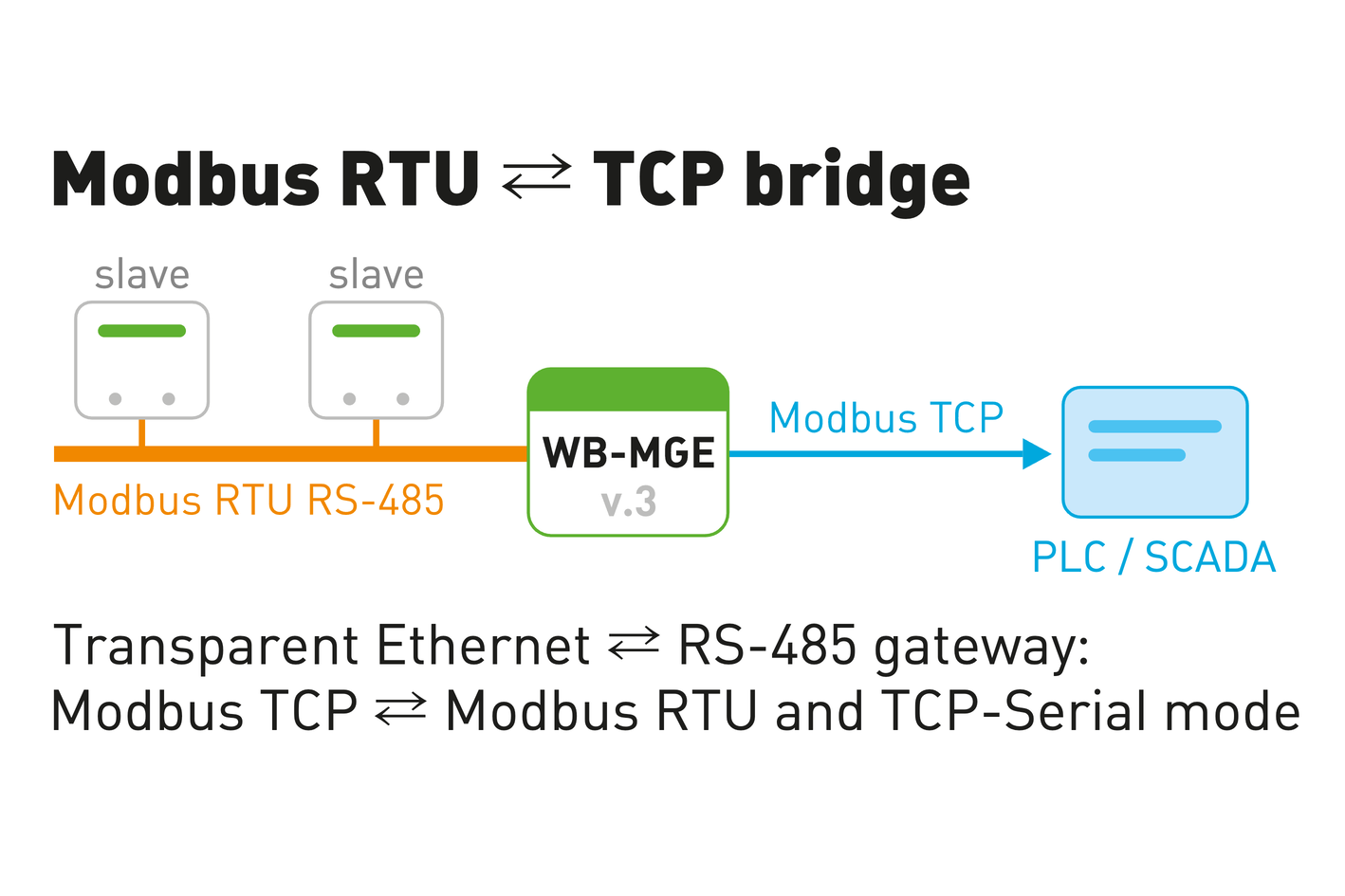
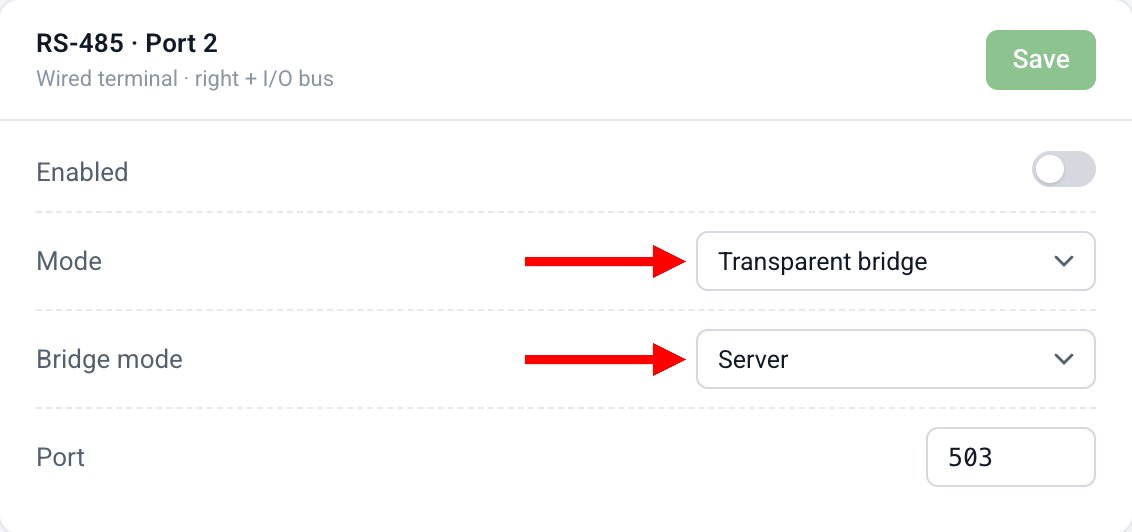
In this mode the module receives, over the network interfaces, TCP packets with data of any protocol (for example, Modbus RTU over TCP) and passes them byte for byte to one of the RS-485 ports. The received response is likewise passed back unchanged to the client the request came from.
The mode is selected for each port separately:
- Go to Modbus Tools → TCP gateway and select the card of the required port.
- In the Mode field select «Transparent bridge» and select the required role in the Role field.
- If necessary, specify the TCP port whose requests will be forwarded to this RS-485 port.
The following roles are available in the «Transparent bridge» mode:
- Server — used when, for example, a Wiren Board controller connects to it.
- Client — used when the WB-MGE v.3 connects to another module of the same kind.
In this mode only one master is allowed.
Sniffer
Available from firmware 1.3.0
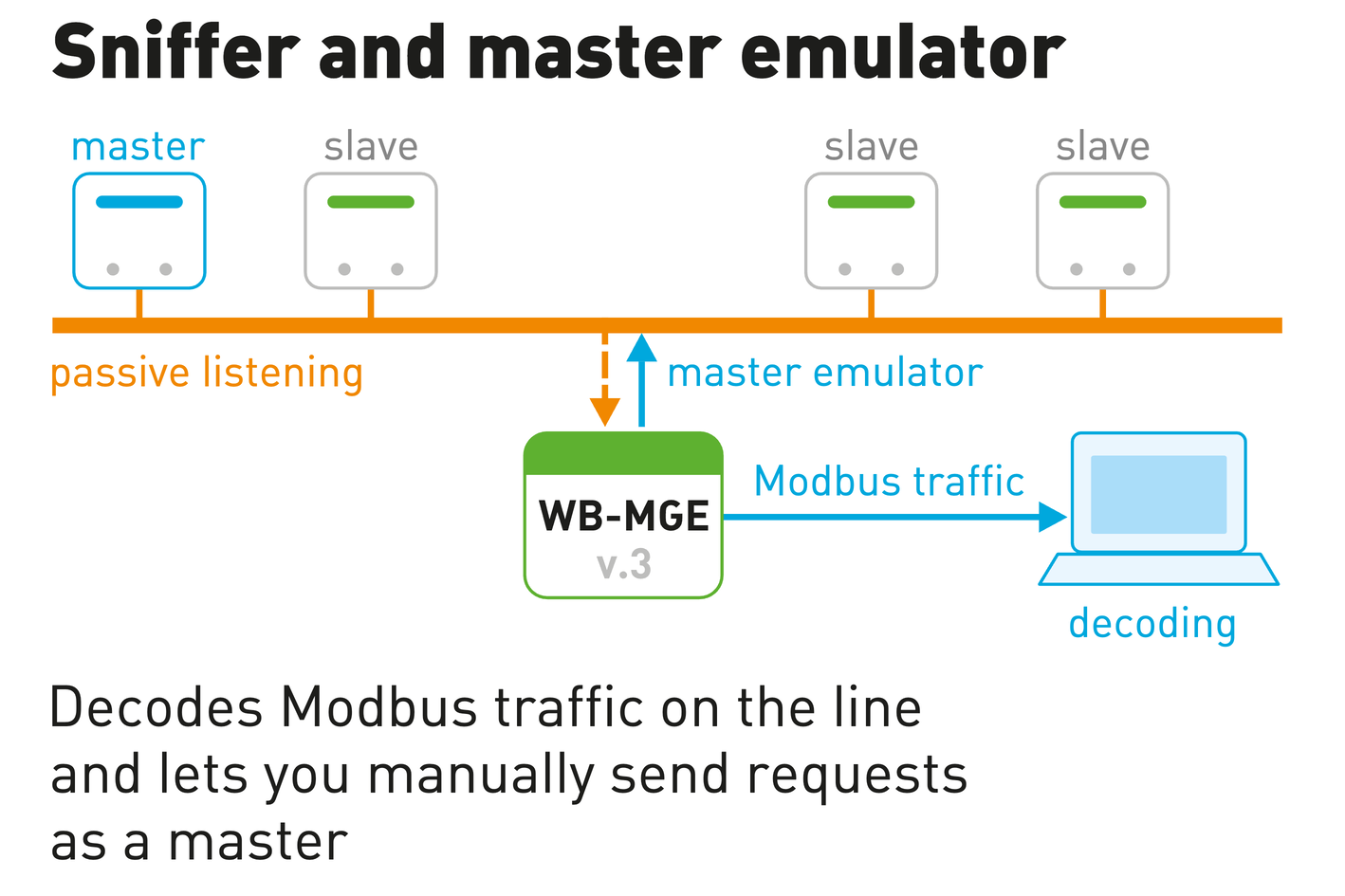
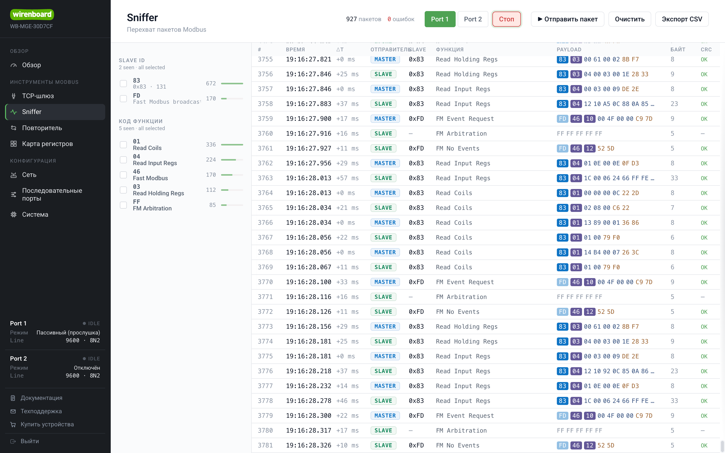
The sniffer captures traffic on the selected RS-485 port in both directions, decodes Modbus frames (including Fast Modbus) and displays them in real time in the web interface over WebSocket. Convenient for diagnosing the exchange without an external analyzer.
Open Modbus Tools → Sniffer, select a port and click Start. For each frame the following is shown: the sender (master/slave), the device address, the function code, the data (HEX), the length and the CRC check result. Available:
- filters by Slave ID and function code, packet and CRC error counters;
- the Send packet button — compose and send a read (FC01–FC04) or write (FC05/06/15/16) request to the bus; the CRC is calculated automatically, a frame preview is shown;
- export of the captured packets to CSV.
The sniffer is an overlay on top of an already open port: it does not switch the transport mode and works in parallel with the cache.
Caching multimaster mode
Available from firmware 1.3.0
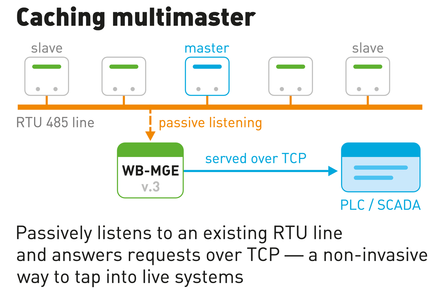
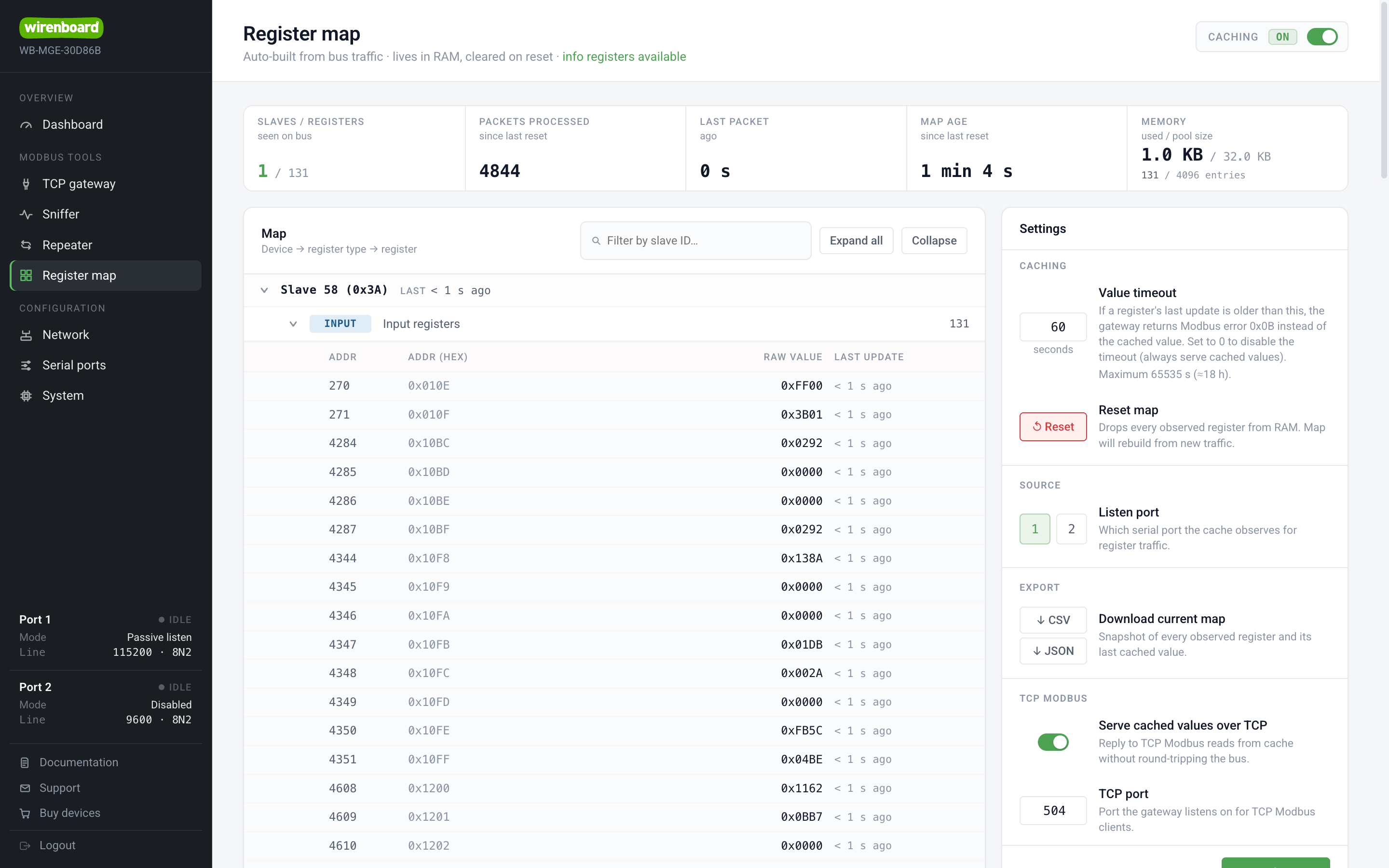
The gateway can passively monitor the Modbus exchange on the bus, remember the latest register and bit values of all devices and serve them over a separate Modbus TCP server (port 504 by default) — without re-polling the devices. This removes the «one master per bus» restriction: the real masters keep polling, while additional TCP clients read the data from the cache.
Open Modbus Tools → Register map and turn on the Caching toggle. On the page:
- the automatically collected map (device → register type → register) and statistics (number of devices, processed packets, map age, memory usage);
- Value timeout — after how many seconds a value in the cache is considered stale. If at the moment of the request the value has not been updated for longer than the timeout, the cache returns not the old number but the Modbus exception 0x0B («gateway target device failed to respond»); 0 disables the check. See below for details;
- Listening port — the source port for the cache; TCP port — the port of the cache Modbus TCP server (504 by default);
- export of the map to CSV/JSON and resetting the map.
How the value timeout works. Every value in the cache has an age counter: it is reset on every new device response on the bus and grows by 1 second per second. On a Modbus TCP request the cache compares the age with the timeout:
- age ≤ timeout — the cached value is served;
- age > timeout — the 0x0B exception is returned instead of the value. This is how the client tells live data from «frozen» data: if a device has disappeared from the bus, its registers start returning an error rather than the last remembered value. When reading a range in a single request, one stale value is enough for the whole response to become the 0x0B exception (a register missing from the cache gives the 0x02 exception).
The age counter is capped and stops at 65535 seconds (≈18.2 hours) — this is also the maximum allowed timeout. Therefore the «shelf life» of a value cannot be set longer than ~18 hours. A special case is a timeout set to the maximum (65535): the age never exceeds this threshold, so the value is never marked stale at all and the check effectively does not fire — the same as with the value 0.
The cache is an independent overlay: it can be enabled on a port in any transport mode (enabling it on a disabled port opens the port in «Passive (listening)» mode).
The gateway's own register map (Unit ID 255)
Available from firmware 1.3.0 The gateway responds over Modbus TCP to a request addressed to its own Unit ID 255 (0xFF) — this address is reserved for the TCP gateway. It works in the «Modbus TCP» and «Cache TCP» modes regardless of the cache state (in Modbus TCP mode such a request is not forwarded to RS-485).
There is a single address space. Functions FC03 (holding) and FC04 (input) functions serve a common map: any address from the table below returns the same value on both functions. In the common Wiren Board register map the fields are formally listed either as input or as holding, but the reference firmware responds with the whole map on both functions, and the standard utilities rely on this: wb-mcu-fw-flasher --get-device-info and modbus_client -t3 -r <address> read the signature and the info block over FC03, while pollers use FC04.
| Address (dec) | Address (hex) | Registers | Type | Description |
|---|---|---|---|---|
| 104–105 | 0x0068–0x0069 | 2 | u32 | Uptime since boot, seconds |
| 121 | 0x0079 | 1 | u16 | Current supply voltage, mV |
| 200–219 | 0x00C8–0x00DB | 20 | string (1 char/reg) | Device model |
| 220–244 | 0x00DC–0x00F4 | 25 | string (2 chars/reg) | Commit hash and the branch the firmware was built from |
| 250–265 | 0x00FA–0x0109 | 16 | string (1 char/reg) | Firmware version (as a string) |
| 266–267 | 0x010A–0x010B | 2 | u32 | Serial number generation scheme (4 — the number is derived from the 48-bit MAC) |
| 268–271 | 0x010C–0x010F | 4 | u64 | Serial number, high word first (the 48-bit MAC in the low bits) |
| 290–301 | 0x0122–0x012D | 12 | string (1 char/reg) | Firmware signature |
| 320 | 0x0140 | 1 | u16 | Firmware version: MAJOR |
| 321 | 0x0141 | 1 | u16 | Firmware version: MINOR |
| 322 | 0x0142 | 1 | u16 | Firmware version: PATCH |
| 323 | 0x0143 | 1 | s16 | Firmware version: SUFFIX (+N for +wbN, −N for -rcN, 0 if none) |
| 324–325 | 0x0144–0x0145 | 2 | u32 | Version in numeric format (word order little-endian: 324 — low word) |
| 326–327 | 0x0146–0x0147 | 2 | u32 | Version in numeric format (word order big-endian: 326 — high word) |
| 330–337 (0x014A–0x0151) — the bootloader version field of the common WB map, not defined here (see below) | ||||
| 528–529 | 0x0210–0x0211 | 2 | u32 | Number of processed packets (since the last cache reset) |
| 530–531 | 0x0212–0x0213 | 2 | u32 | Seconds since the last packet on the bus |
| 532 | 0x0214 | 1 | u16 | Number of devices on the bus (unique slave_id values in the cache) |
| 533 | 0x0215 | 1 | u16 | Average bus polling rate, polls/min |
| 534 | 0x0216 | 1 | u16 | Cache value timeout, seconds |
| 65505 | 0xFFE1 | 1 | u16 | Total RAM, KB |
| 65506 | 0xFFE2 | 1 | u16 | Amount of used RAM, KB |
| 65507 | 0xFFE3 | 1 | u16 | Amount of free RAM, KB |
| 65508 | 0xFFE4 | 1 | u16 | Cause of last MCU reset |
Notes on the register map:
- String packing differs between fields — this is dictated by the common Wiren Board register map, otherwise the standard utilities read garbage:
- 1 character per register, the character in the low byte (the high one is 0x00): model (200–219), firmware version (250–265), signature (290–301). The sign of this layout is that the number of registers equals the number of characters. The standard calls
modbus_client -t3 -r 290 -c 12 | sed 's/ 0x00/\x/g'andwb-mcu-fw-flasher --get-device-info; - 2 characters per register, the first character of the pair is in the low byte, the second in the high one: git info (220–244, 25 registers = 50 characters).
- The tail of a field is padded with zeros.
- 1 character per register, the character in the low byte (the high one is 0x00): model (200–219), firmware version (250–265), signature (290–301). The sign of this layout is that the number of registers equals the number of characters. The standard calls
- Serial number is laid out according to the reference WB map: 266–267 — the generation scheme, 268–271 — the value itself. Reading 270–271 as a separate request gives the low 32 bits of the number — the same as in the reference map.
- The bootloader zone 330–337. The bootloader version field of the common WB map is read as eight registers starting at address 330 (
modbus_client -t0x03 -r330 -c8), so the whole range is left unoccupied — there are no registers of our own here, all the more so on FC03. For the same reason the statistics block is moved outside the common WB map, to 528–534 — seven consecutive registers are read in a single request. - Multi-register integers (except 324–325) are stored in big-endian word order — the high word at the lower address.
- The numeric version is calculated according to the Wiren Board rule (Modbus-hardware-version):
if (SUFFIX >= 0) enc = SUFFIX + 128; else enc = -1 - SUFFIX;VERSION = (MAJOR << 24) | (MINOR << 16) | (PATCH << 8) | enc. - Memory (65505–65507) follows the order of the common WB map — total, used, free — but in kilobytes, not in bytes: the internal ESP32 heap amounts to hundreds of kilobytes, and a byte value would hit the u16 ceiling (65535). «Total» here is the memory managed by the allocator (around 300 KB), not the whole SRAM of the chip. Register 65504 (maximum used stack) is not implemented: the firmware is multitasking, it has no single stack, and reading this address returns exception code 0x02.
- The reboot reason (65508): 1 — LPWR (brownout/wake from sleep), 2 — WWDG (interrupt watchdog), 3 — IWDG (task/general watchdog), 4 — SFT (software reset/panic), 5 — POR (power-on), 6 — PIN (external reset), 0 — unknown.
- The bus statistics (528–534) are taken from the multimaster cache; when the cache is inactive the corresponding fields read as 0.
- Reading a range where at least one address is undefined returns the 0x02 exception (illegal data address); a function other than FC03/FC04 — the 0x01 exception (illegal function). No more than 125 registers are read in a single request.
Serial repeater
Available from firmware 1.3.0
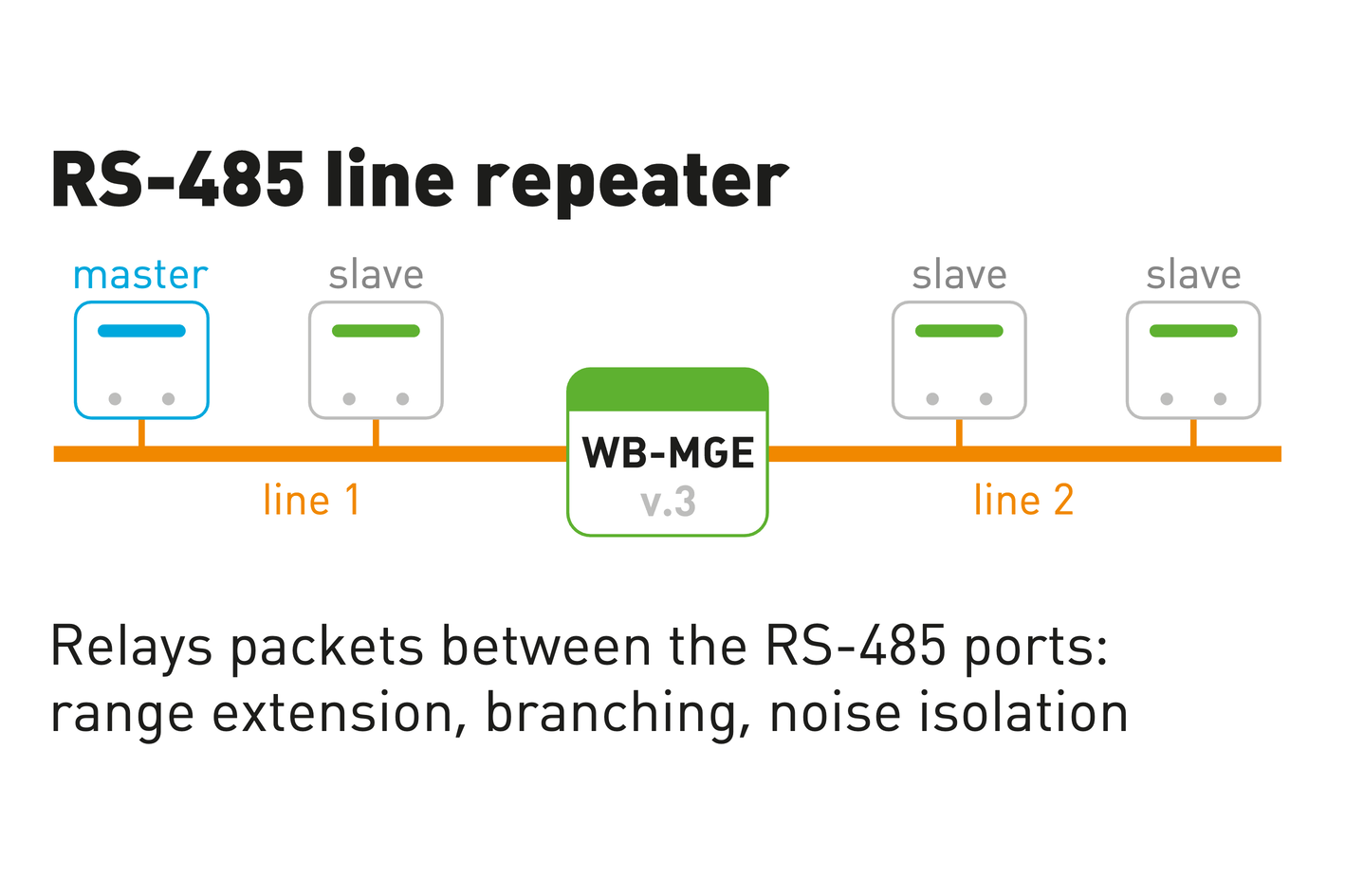
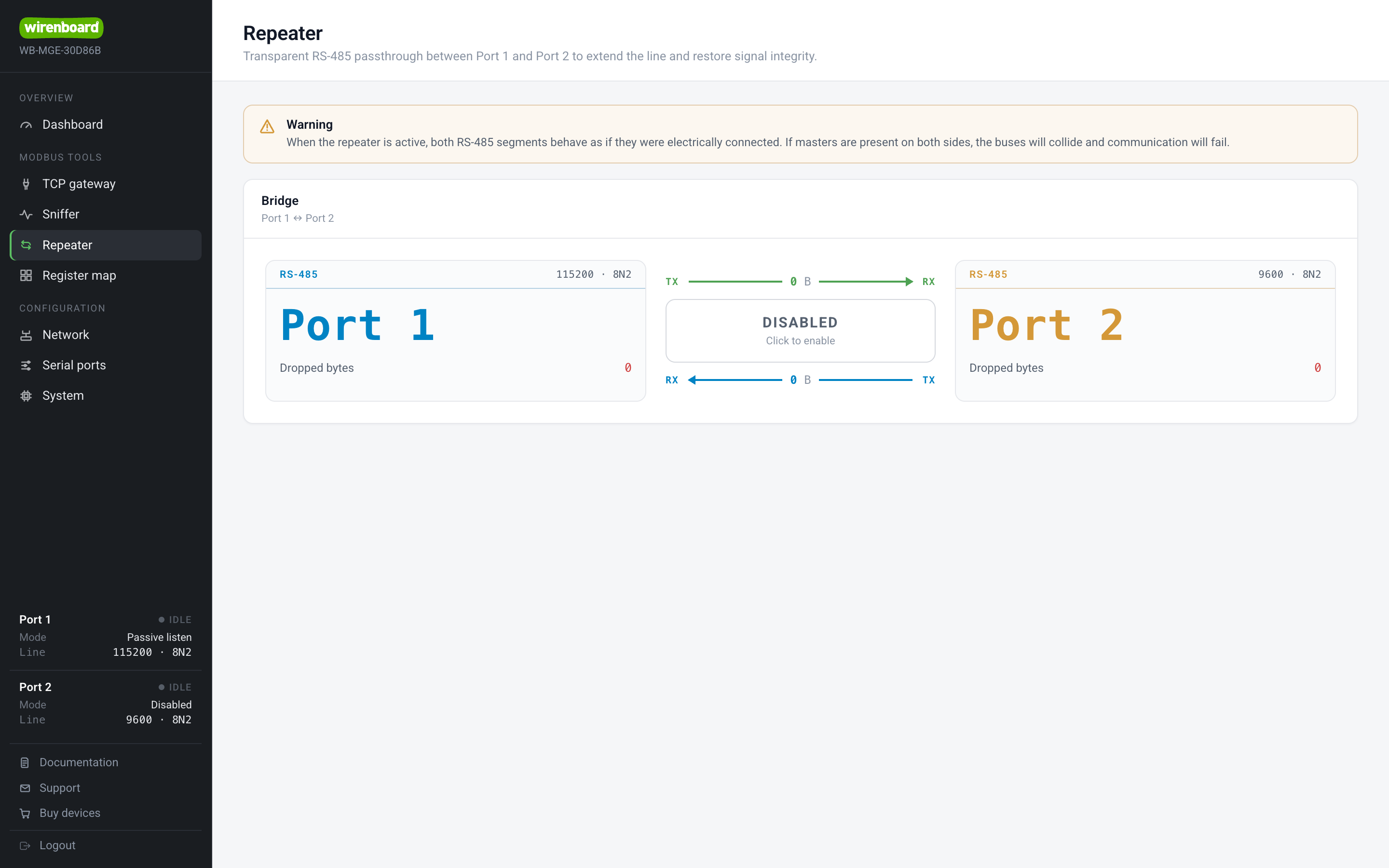
The repeater is a transparent «Serial↔Serial» transfer: the bytes received on Port 1 are forwarded byte by byte to Port 2 and vice versa, without parsing frames. It is used to extend an RS-485 line and to restore signal integrity.
Open Modbus Tools → Repeater and click the toggle — it switches both ports into repeater mode (clicking again turns it off). The page shows the forwarding statistics in real time: bytes forwarded in each direction, bytes lost on each port, uptime and average speed.
Bytes lost is the counter of bytes received on a port that could not be forwarded to the opposite port (its transmit buffer is full): the incoming stream briefly exceeded the transmit throughput. In normal operation it is zero.
Different port speeds. The port speeds are independent, and the repeater can work at different speeds, but not always reliably. It works best in the asymmetric case: the master on the slow line (for example, 9600), the slave on the fast one (for example, 115200). Then the master sends requests slowly, and only the responses to its requests are relayed back — there is little oncoming traffic. But even so the line can be overloaded if a very large chunk of data is requested in a single request: the size of one frame is limited by a 1000-byte buffer, and if the slave responds with a packet longer than that, the frame will overflow the buffer and will be dropped already on reception.
Attention: while the repeater is active, both RS-485 segments behave as if electrically connected. If there are masters on both sides of the bus, collisions on the bus and loss of communication are possible. This is a local connection of two ports of one module; joining segments through two modules over IP is described in the section Repeater using two modules over TCP.
Repeater mode limitations
They apply to both schemes — the Port 1 ↔ Port 2 bridge and two modules joined over TCP.
Fast Modbus. Devices with events must all be on the same side of the repeater. A single Wiren Board device on one segment is enough for events from the rest of the bus to stop being delivered.
There are two ways to meet this requirement:
- one of the segments has no Wiren Board devices at all — only the WB-MGE v.3;
- or event polling is disabled on all devices on the bus (how to disable event polling).
Response timeout. In the RS-485 port settings of the wb-mqtt-serial driver, explicitly set «Response timeout» to at least 200–250 ms.
Delay before writing to the port. Required if, besides the WB-MGE v.3, slave devices are connected to the bus on the controller side: it keeps a reply delayed by the repeater from overlapping the next request. At least 50000 µs for 9600 baud; the value can be reduced as the speed increases.
Scanning. Fast device discovery through the repeater finds only the devices of the segment the controller is connected to. Look for devices beyond the repeater with the slow scan (scanning devices on the bus). It requires «Response timeout» and «Delay before writing to the port» to be set — without them the scan returns an empty result.
Repeater using two modules over TCP
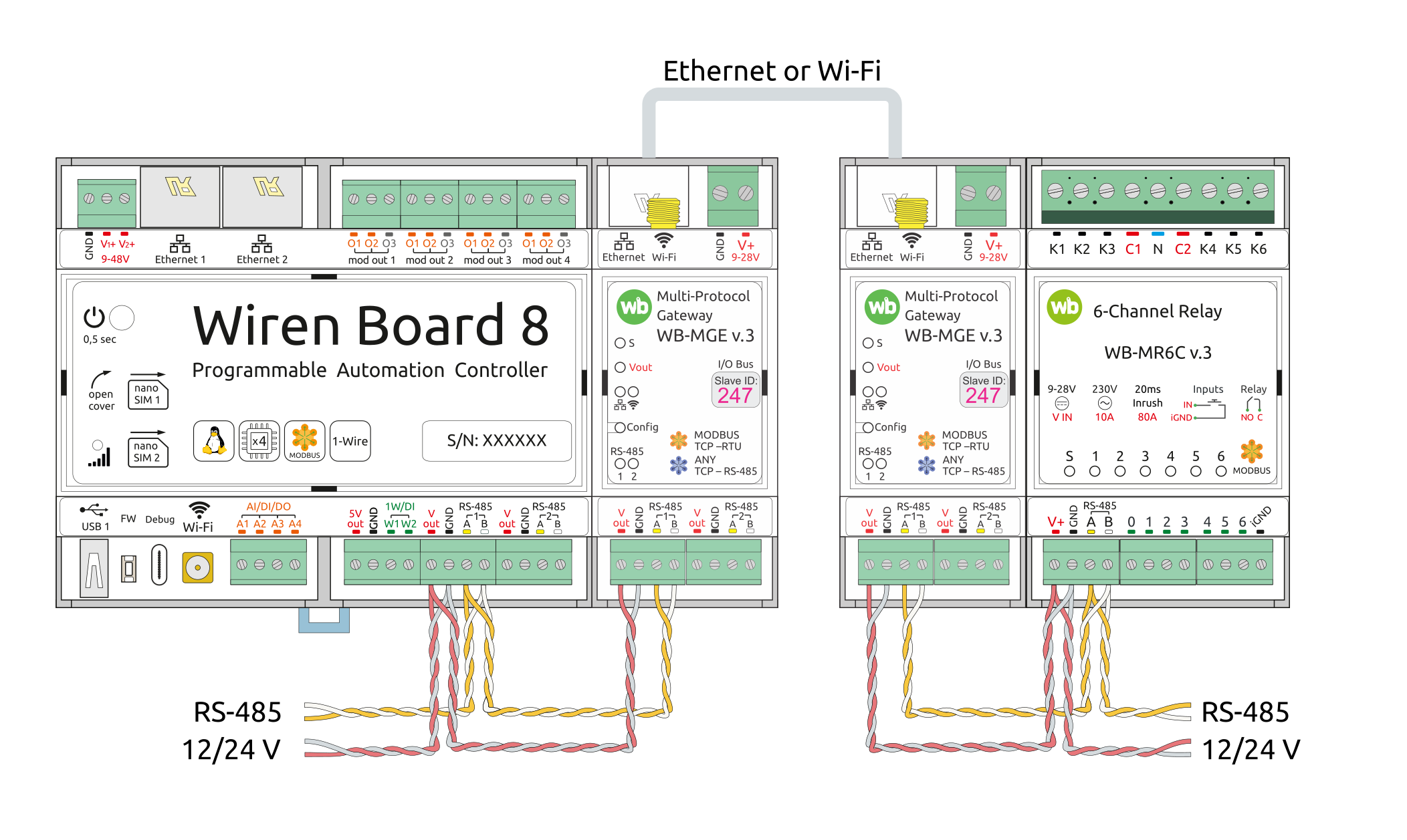
To connect two RS-485 bus segments over a LAN or VPN using WB-MGE v.3, set one module to Transparent mode with the role Server, and the other to Transparent mode with the role Client , specifying the server IP address.
If the modules are connected directly without a switch or DHCP server, assign both static IP addresses in the same subnet under Configuration → Network → Ethernet.
Important! This arrangement is recommended only when the WB-MGE v.3 gateway cannot be connected directly to the Wiren Board controller over Ethernet or Wi-Fi. It is subject to the repeater mode limitations, with one change: set Response timeout to at least 350 ms when using Wi-Fi or a VPN.
I/O Bus (WBIO side expansion modules)
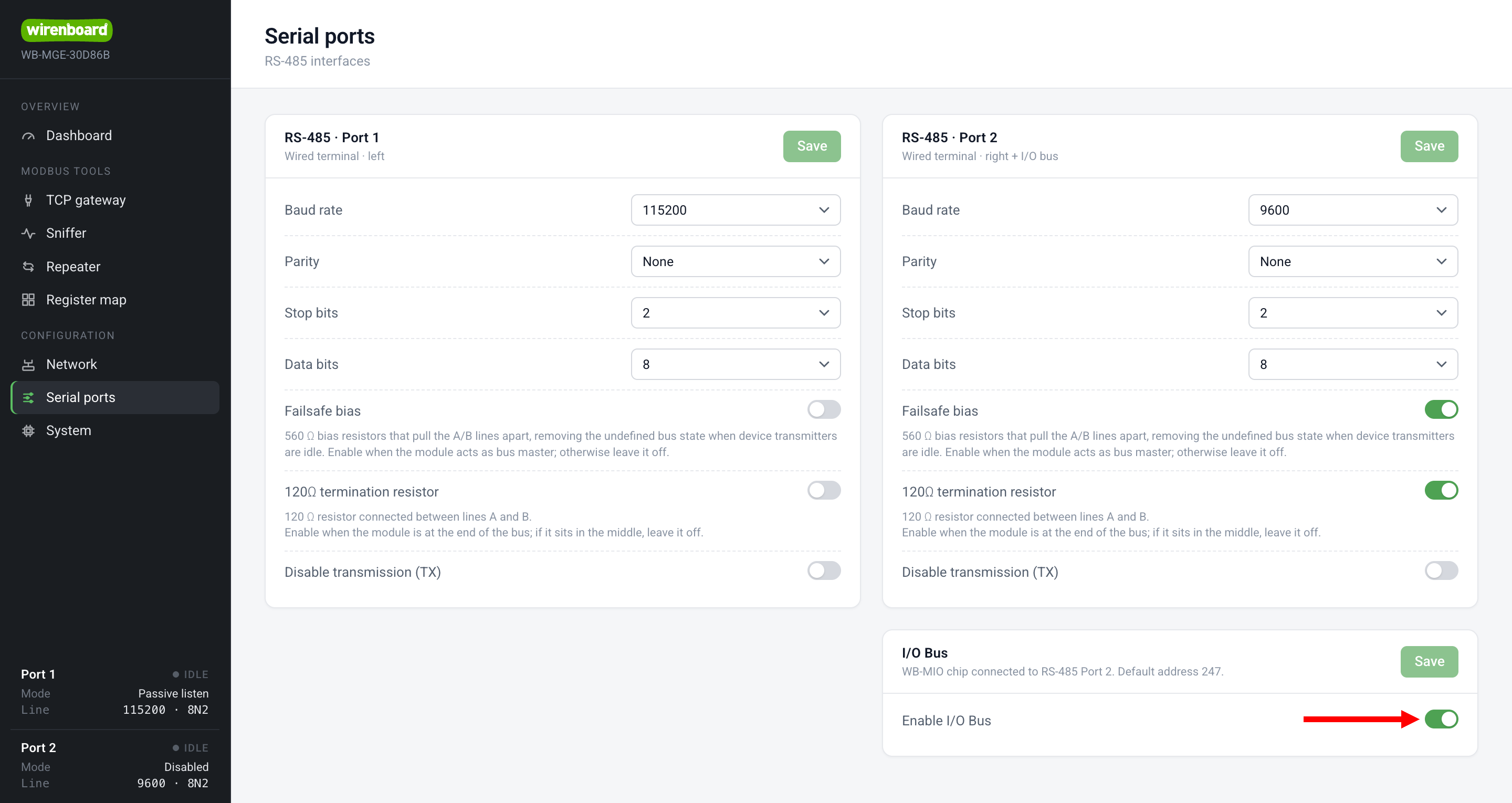
Side modules operate through the built-in WB-MIO, which presents them as a Modbus device on RS485-2 with the standard Wiren Board defaults:
- address: 247;
- communication settings: 9600 8N2.
To enable or disable the built-in WB-MIO in the module web interface:
- Go to Configuration → Serial ports and find the card I/O Bus.
- Set Enable I/O Bus to the required state.
WB-MIO is enabled by default. Disable it to free its Modbus address or to use a protocol on RS485-2 that conflicts with Modbus RTU.
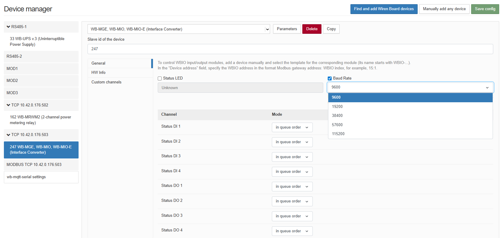
Important! The communication settings of connected devices and the built-in WB-MIO must match. If connected devices use different settings, change the WB-MIO settings by writing new register values. You can write values:
- in the controller web interface through the driver settings wb-mqtt-serial;
- from the controller SSH console using Modbus-client; RS485-2 must be in Modbus TCP mode;
- Stop the wb-mqtt-serial driver:
systemctl stop wb-mqtt-serial
- Write the new WB-MIO RS-485 baud-rate value:
modbus_client --debug -mtcp -a247 -c1 -r110 -t0x06 -o300 -p503 10.42.0.176 1152
- where
247is the WB-MIO address,10.42.0.176is the module IP address,1152corresponds to 115,200 bit/s with the register’s ×100 scaling.
- Start the wb-mqtt-serial driver:
systemctl start wb-mqtt-serial
- Stop the wb-mqtt-serial driver:
- by connecting directly to RS485-2 through the WB-USB485 interface converter.
| Address | Register parameters | Description | Values | Note | |||
|---|---|---|---|---|---|---|---|
| Dec | Hex | Type | Access | Format | |||
| Connection settings | |||||||
| 110 | 0x006E | Holding | RW | u16 | RS-485 baud rate. RS-485 connection parameter settings |
×100, baud 12 — 1200 bit/s, 24 — 2400 bit/s, 48 — 4800 bit/s, 96 — 9600 bit/s, 192 — 19200 bit/s, 384 — 38400 bit/s, 576 — 57600 bit/s, 1152 — 115200 bit/s |
|
| 111 | 0x006F | Holding | RW | u16 | RS-485 parity setting | 0 — no parity (none), 1 — odd, 2 — even |
|
| 112 | 0x0070 | Holding | RW | u16 | RS-485 stop bits See: stop-bit tolerance |
1, 2 | |
| 128 | 0x0080 | Holding | RW | u16 | Device Modbus address (details) | ||
Selecting the port mode
The mode is selected separately for each port according to the devices connected to the RS-485 bus. Selecting the wrong mode disrupts communication with all devices behind the gateway.
| Devices connected to the bus | Mode to select |
|---|---|
| Wiren Board devices only | Either: Fast Modbus works in both modes. See repeater mode limitations |
| Wiren Board devices together with third-party Modbus devices | Modbus TCP: the gateway manages the order of bus requests |
| Devices that do not use Modbus (for example, curtain motors) | Transparent bridge only |
Flashing devices behind the gateway using socat
|
Transparent bridge. See Updating Modbus device firmware |
Testing with the utility modbus_client -mtcp
|
Modbus TCP only. In Transparent bridge mode, the utility reports Invalid transaction ID or a timeout
|
| Several clients on one port | Modbus TCP or a caching multimaster |
Configuration
Web interface
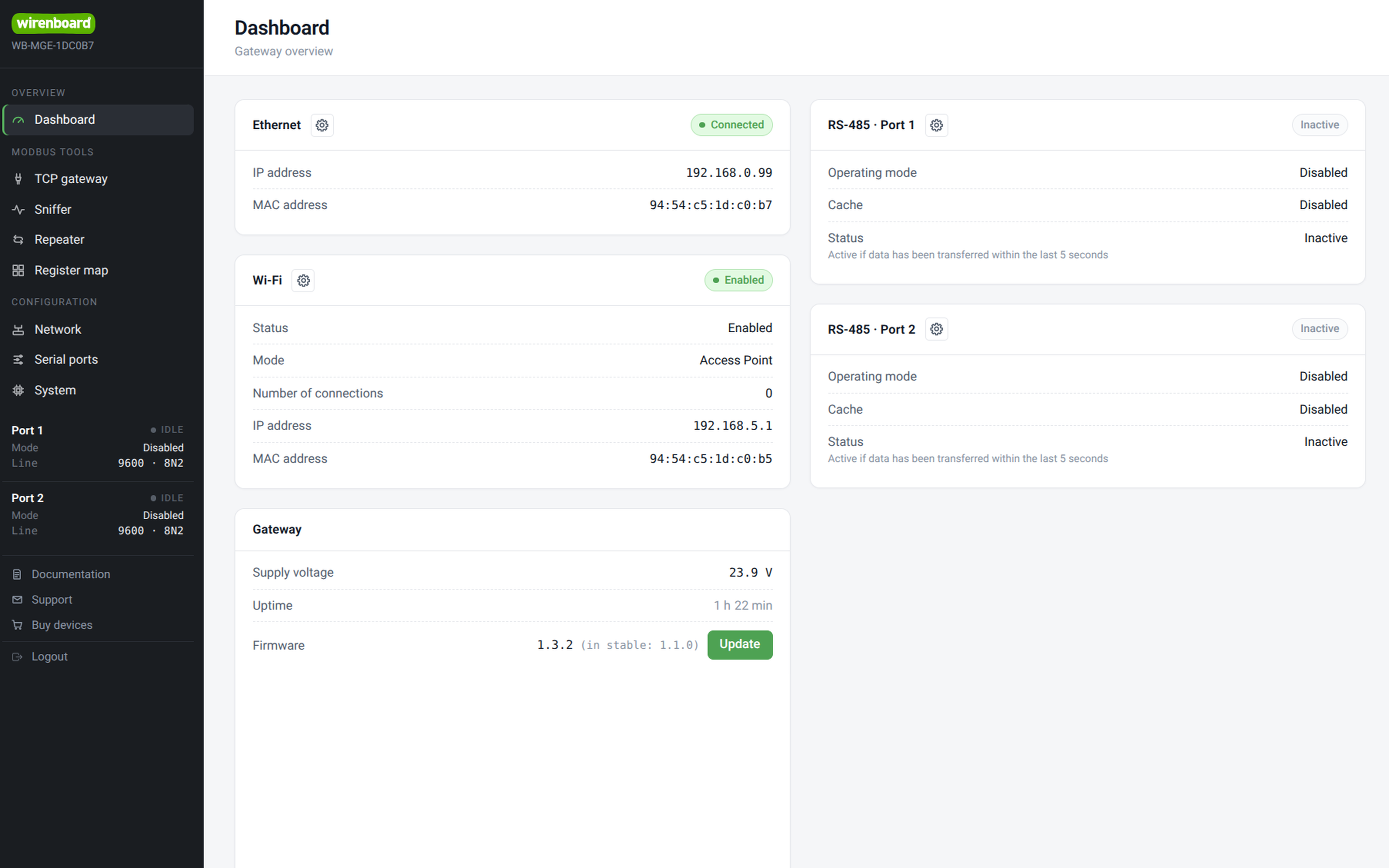
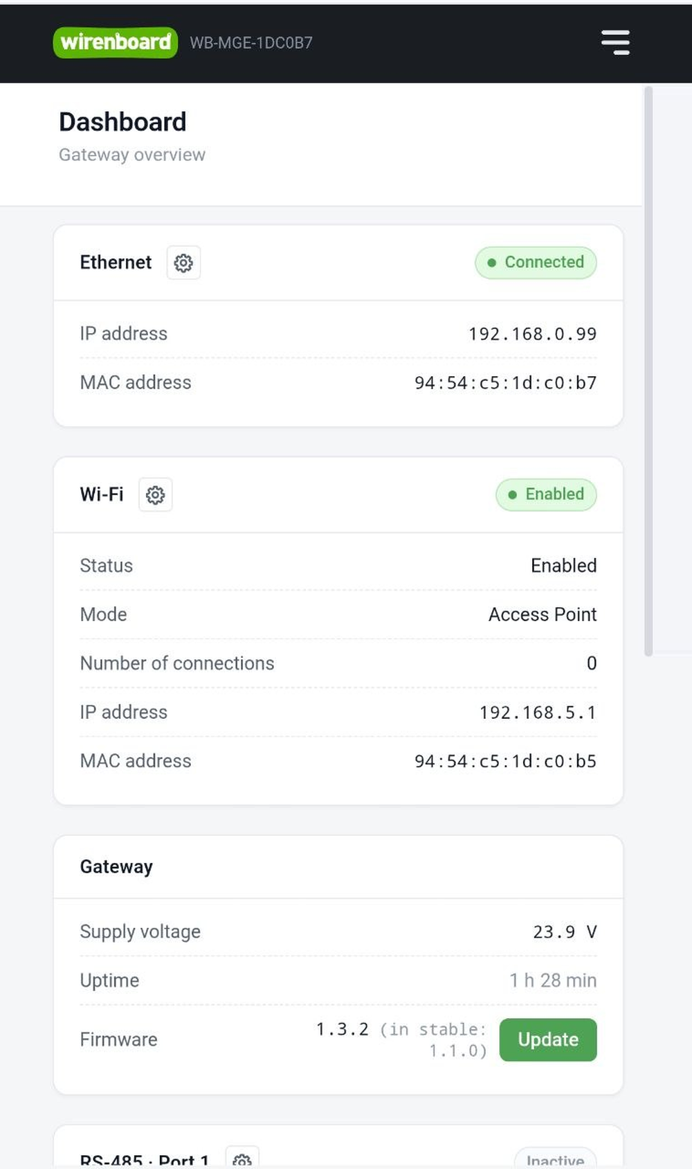
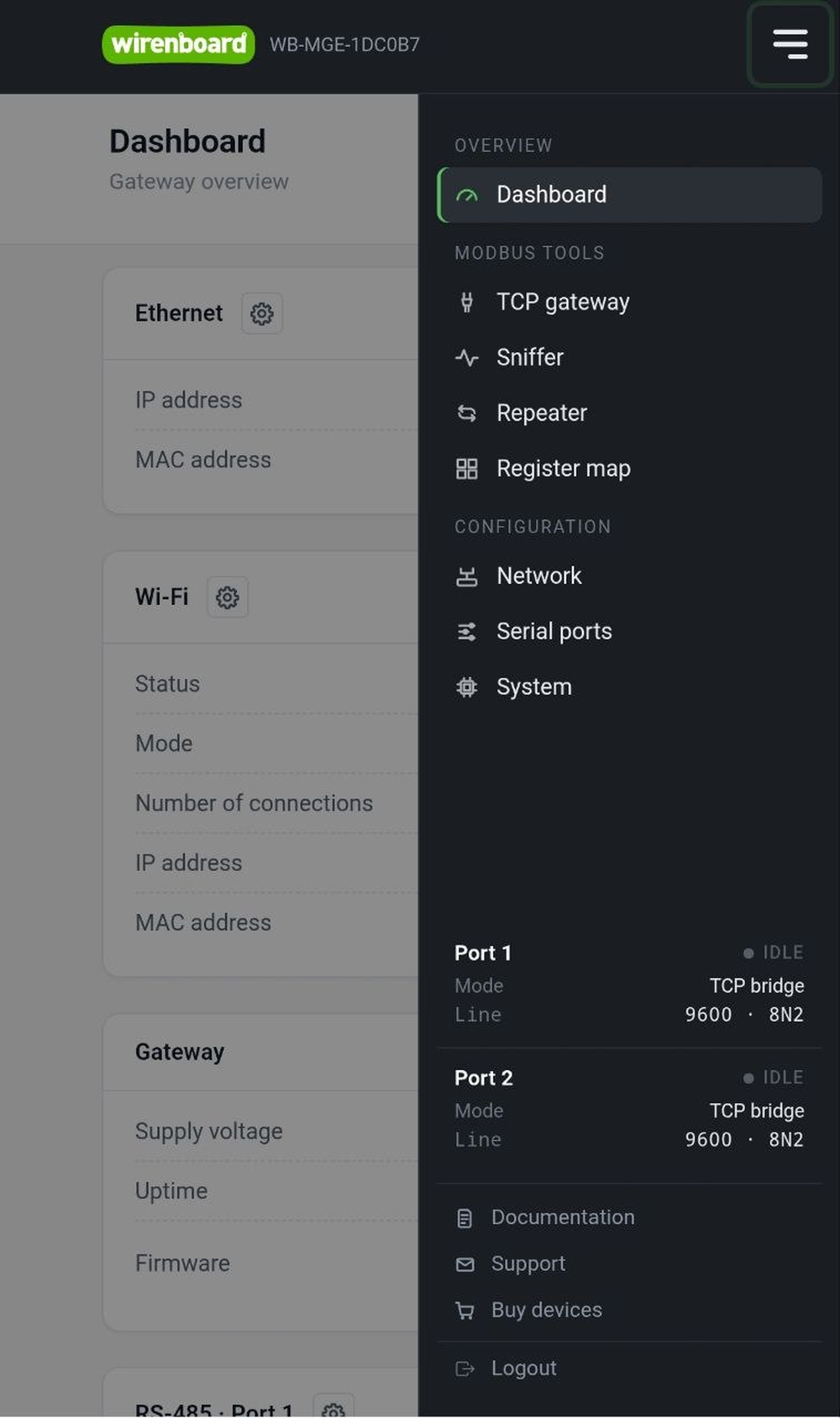
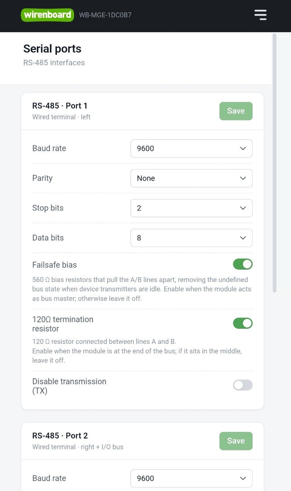
For convenient configuration the module has a web interface that works in modern browsers on a computer and on mobile phones. To access it you need to connect the computer and the module to the same network through one of the interfaces:
- Wi-Fi, where it brings up an access point and automatically assigns IP addresses to the clients.
- Ethernet, here no IP addresses are configured, the module must obtain them over DHCP, for example, from your router.
The default values are given in the table below. Information about the network settings is also printed to the debug console available through the USB-C connector under the cover of the module.
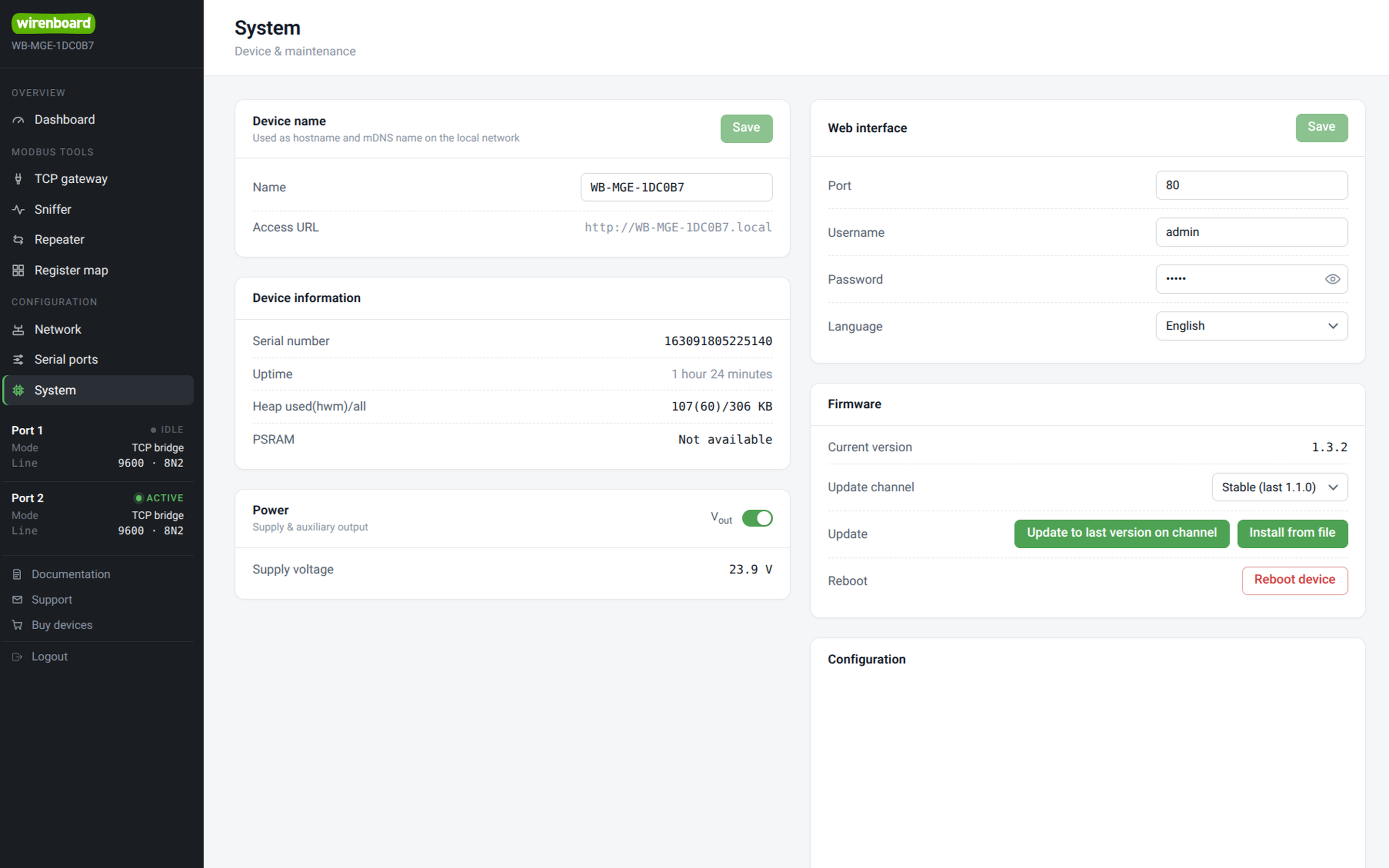
- Web interface screenshots
-
-
-
-
-
-
| Overview | |
|---|---|
| Login | admin |
| Password | admin |
| mDNS host name | wb-mge-XXXXXX.local, where XXXXXX are the last three bytes (six hexadecimal digits, without separators) of the Ethernet MAC address
You can also take the name of the access point printed on the label and append .local to it |
| Wi-Fi | |
| Access point | WB-MGE-XXXXXX, where XXXXXX are the last three bytes (six hexadecimal digits, without separators) of the Ethernet MAC address. |
| Key (password) | printed on the label on the side of the device. |
| IP address | 192.168.5.1 |
| Subnet mask | 255.255.255.0 |
| Ethernet | |
| IP address | DHCP |
| Subnet mask | DHCP |
Accessing the web interface
Via a Wi-Fi access point
By default Wi-Fi works in access point mode:
- Open the list of Wi-Fi access points on your laptop or phone and connect to WB-MGE-XXXXXX, where XXXXXX are the last three bytes (six hexadecimal digits, without separators) of the Ethernet MAC address.
- Enter the security key (password) printed on the label on the side of the device.
- The web interface will be available at 192.168.5.1, login / password — admin / admin.
Over Ethernet
By default the Ethernet port of the module is configured to obtain an IP address over DHCP, so you will need a router with IP address distribution configured — usually this is any router installed in a flat or an office:
- Connect the module to the router over Ethernet;
- Go to the settings of your router and see which IP address it has assigned to the module.
- Open a web browser on a computer connected to the same router. The web interface will be available at the IP address from the previous step, login / password — admin / admin.
Via the controller Ethernet port
If the module is connected to the Ethernet port of the controller and is on a different subnet, its web interface can be accessed through an SSH tunnel. In the example below you connect from your computer to the controller with the address 192.168.42.1, and the module has the address 192.168.0.7.
- Create an SSH tunnel:
- On Linux/macOS (OpenSSH) or Windows (PowerShell / CMD):
ssh -N -L 8088:192.168.0.7:80 root@192.168.42.1
- When prompted for the password enter — wirenboard (the default password). The -L option forwards the local port 8088 to 192.168.0.7:80 through the controller, -N does not run a remote command. If port 8088 is busy, specify another free local port. Keep the session open while you use the web interface.
- On Windows (PuTTY):
- In the Session category, enter the following address in the Host Name field: 192.168.42.1, then go to Connection → SSH → Tunnels.
- In the Source port field, enter 8088.
- In the Destination field, enter 192.168.0.7:80.
- The tunnel type is Local. Click Add.
- Return to Session, click Open and log in as the user root.
- On Linux/macOS (OpenSSH) or Windows (PowerShell / CMD):
- Open the web interface in a browser at the address, enter the login and the password:
http://127.0.0.1:8088/
Via Wiren Board Cloud
If the WB-MGE v.3 is connected to one of the network interfaces of the controller, and the controller is in Wiren Board Cloud — the web interface of the module can be proxied and accessed through the cloud. Details in Getting access to arbitrary web interfaces on the controller.
Module network configuration
The module can connect to the network over Ethernet and/or Wi-Fi, independently of each other.
Ethernet. Go to Configuration → Network → Ethernet:
- DHCP client (enabled by default) — the module obtains an IP address automatically from the router;
- Static IP address — when the DHCP client is disabled, set the IP address, subnet mask and gateway manually.
Wi-Fi. Configuration → Network → Wi-Fi, mode:
- Access point (AP) — the default mode, the module creates its own network
WB-MGE-XXXXXX(see #Via a Wi-Fi access point); the SSID, password, authentication type and the IP parameters of the created network itself (address, mask, gateway) are set here; - Client (station) — the module connects to an already existing Wi-Fi network as an ordinary device; specify the SSID and password of that network, and either the DHCP client or a static IP address/mask/gateway to obtain an address in it;
- Disabled — the module's Wi-Fi interface is switched off completely (for permanent disabling with no way to switch it back on, see #Permanently disabling Wi-Fi).
Ethernet and Wi-Fi can be used simultaneously (for example, Wi-Fi in access point mode for the initial setup, Ethernet — for permanent operation).
- Note. Configuring a DNS server is not provided for in the current firmware — the module works in the local network by IP addresses without resolving external domain names.
Saving and loading the configuration
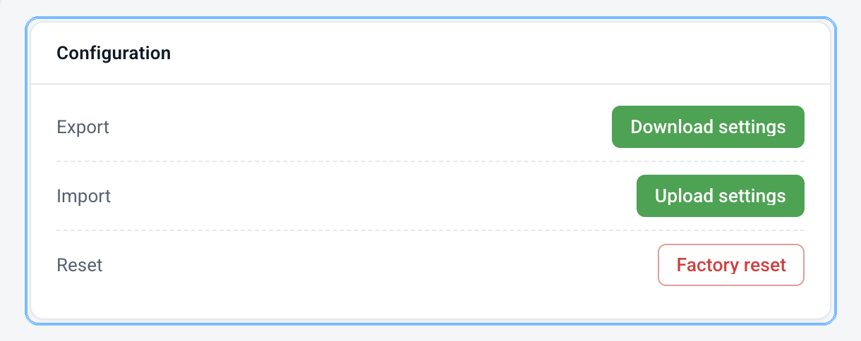
The configured parameters can be saved to a file and used to restore them on a new device or when creating identical installations.
All the settings of the web interface, the ports and the network interfaces are exported to the file.
Termination and fail-safe biasing
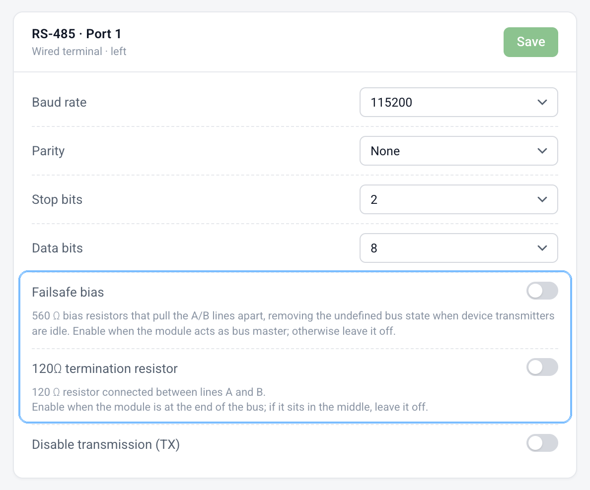
The module has the following installed and enabled by default:
- terminator — a 120 Ohm resistor connected between lines A and B. If the module is at the end of the bus — it must be enabled, if in the middle — disabled.
- fail-safe biasing — 560 Ohm pull-up and pull-down resistors that establish a defined idle differential voltage on the RS-485 bus while all transmitters are inactive (high impedance), preventing spurious reception. If the module works as a master — it must be enabled, in all other cases disabled.
The control is done in software: go to Configuration → Serial ports and set the required status in the card of the required port.
Disabling transmission (TX)
Available from firmware 1.3.0
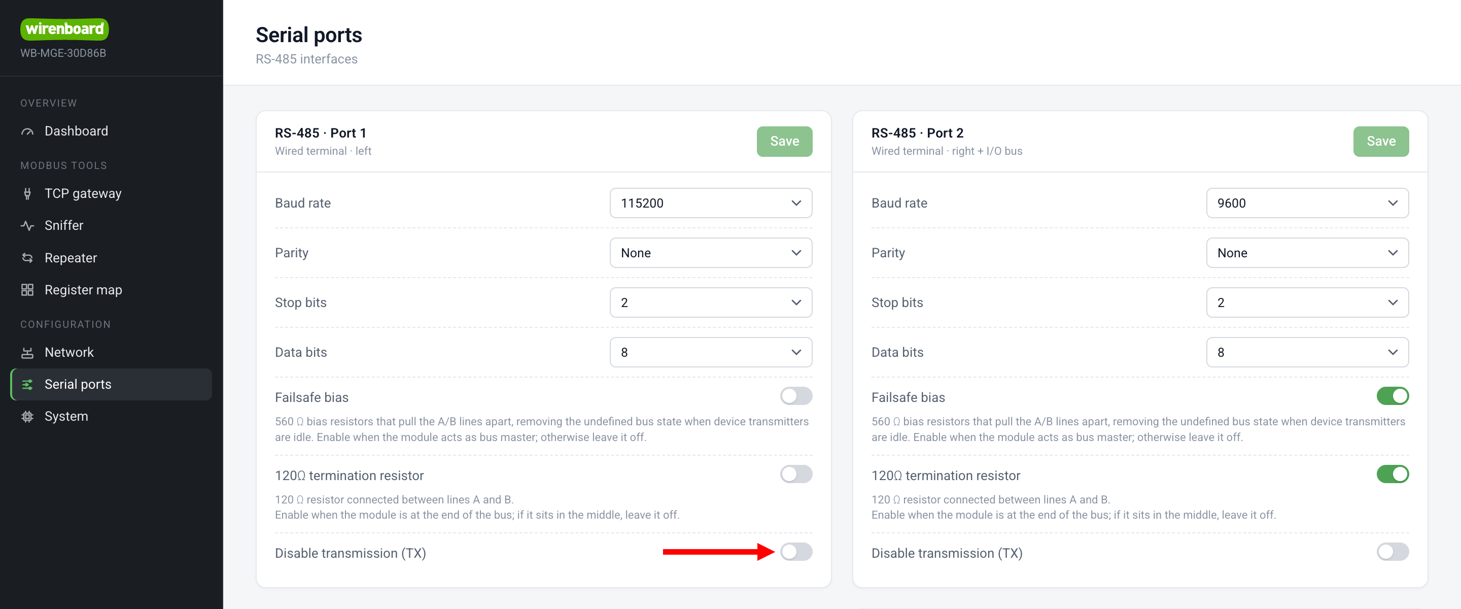
For each RS-485 port on the Configuration → Serial ports page there is a Disable transmission (TX) toggle. It physically switches the RS-485 transceiver into receive-only mode: the direction control pin (DE) is detached from the UART and held in the inactive state. While the mode is on, it is impossible to send anything to the line even in software — any attempt to transmit is silently discarded.
This makes it possible to safely connect to already operating installations and to analyze or mirror their traffic (with the sniffer or the caching multimaster) without the fear that an accidental transmission will disrupt the system. If a port is switched into receive-only mode, the Send packet button in the sniffer is unavailable.
Permanently disabling Wi-Fi
Available from firmware 1.3.0 The WB-MGE supports the permanent Wi-Fi disabling mode. After activation the Wi-Fi driver is no longer initialized — the radio module stays off on all subsequent boots, and the Wi-Fi settings section is hidden in the web interface. This mode cannot be undone through the API.
Activation through the API (requires a reboot to take effect):
# First, authenticate
curl -s -c cookies.txt -X POST http://192.168.0.7/auth -H 'Content-Type: application/json' -d '{"login":"admin","pass":"admin"}'

# Permanently disable Wi-Fi
curl -s -b cookies.txt -X POST http://192.168.0.7/settings -H 'Content-Type: application/json' -d '{"wifi_perm_disable": true}'

# Reboot to apply the changes
curl -s -b cookies.txt -X POST http://192.168.0.7/cmd -H 'Content-Type: application/json' -d '{"cmd": "reboot"}'
After the reboot GET /settings does not return the wifi group and contains "wifi_perm_disable": true. Sending {"wifi_perm_disable": false} is silently ignored.
This operation is irreversible through the API. To restore Wi-Fi, perform a factory reset with the Config button (hold for 5 seconds) or reflash the device.
Wiren Board controller configuration
The module and the controller must be on the same IP network. Choose one of the connection options below, set up the network, and then add the module ports to the wb-mqtt-serial driver. How to open the web interface of the module is described in the #Accessing the web interface.
The controller and the module are connected to the same network via a router and obtain IP addresses via DHCP
-
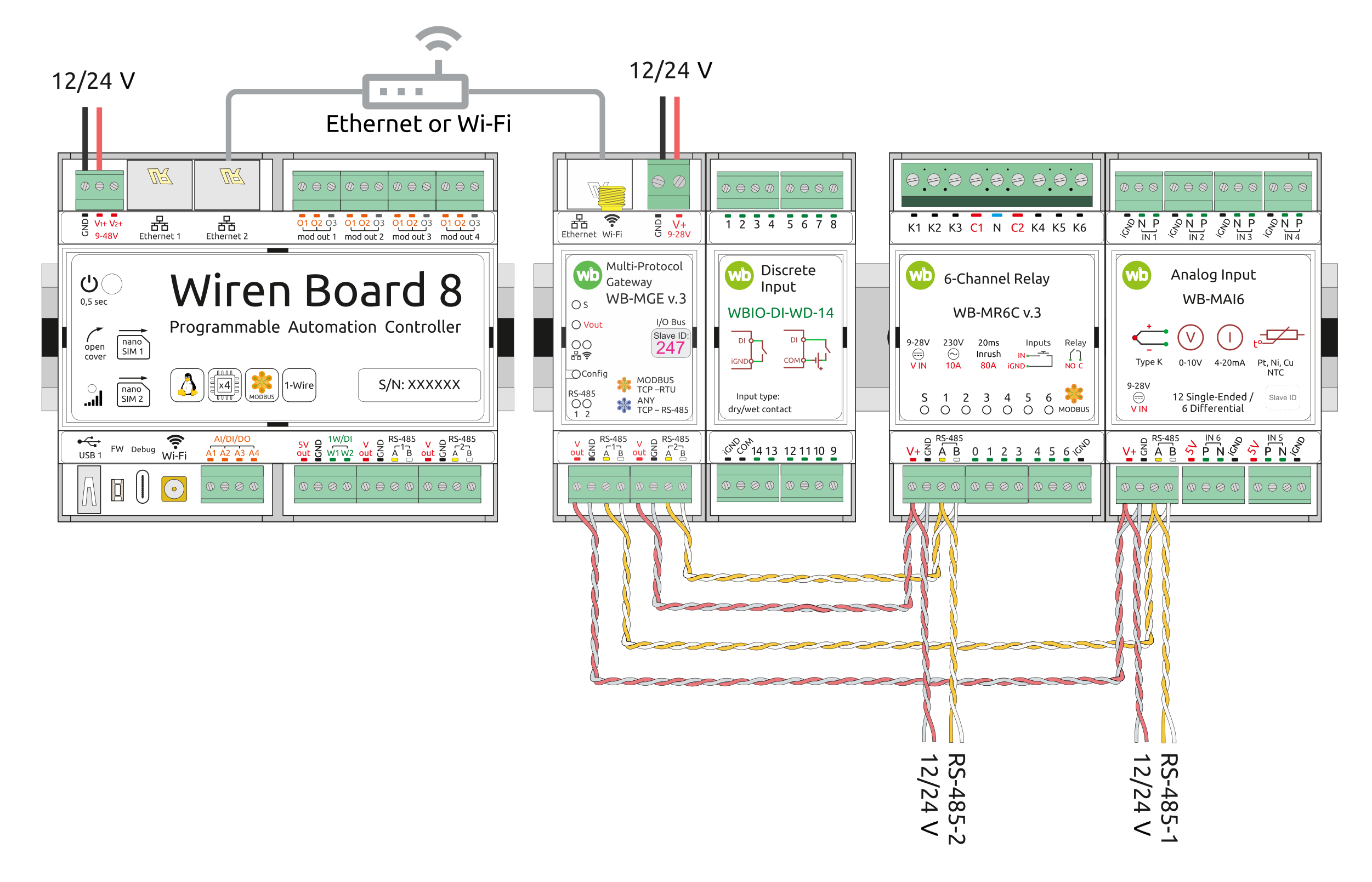 Connection diagram
-
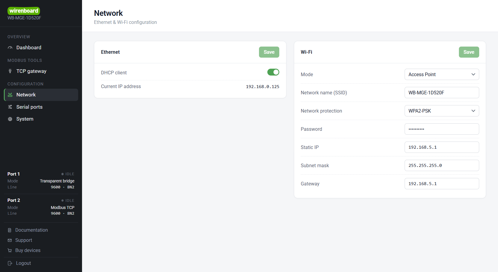 WB-MGE v.3 module settings, the obtained IP address 192.168.0.125
-
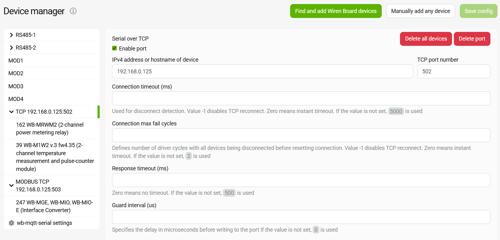 Port settings in wb-mqtt-serial
- Connect the controller and the module to the router over Ethernet. The network settings of the module do not need to be changed: by default it obtains an IP address via DHCP.
- Find out the IP address of the module in the web interface of the module (Configuration → Network) or in the client list of the router.
The controller is connected to the module over Ethernet, the controller — IPv4 Shared with other computers, the module — DHCP Client
-
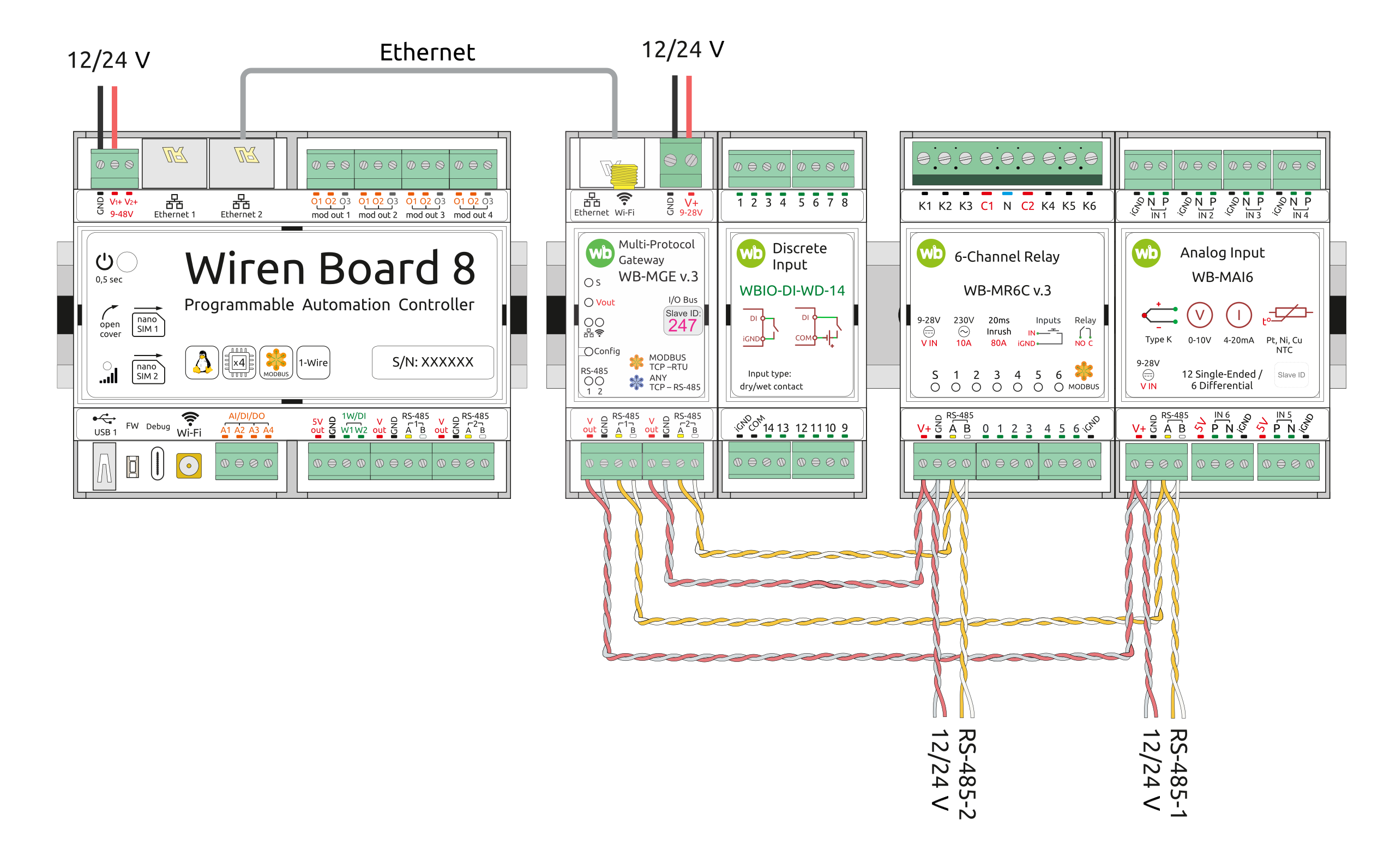 Connection diagram
-
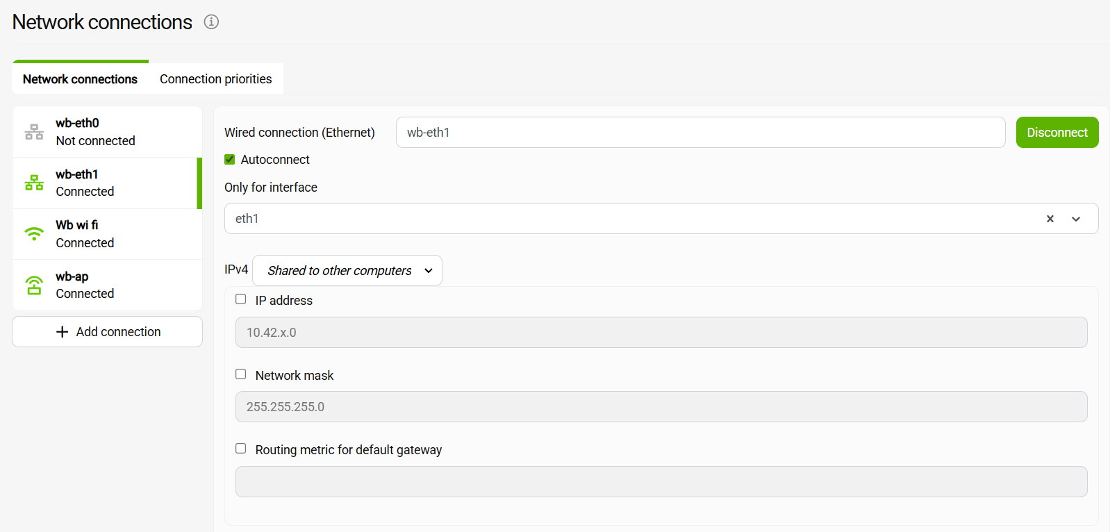 Configuring the Ethernet 2 port on the controller, IPv4 Shared with other computers
-
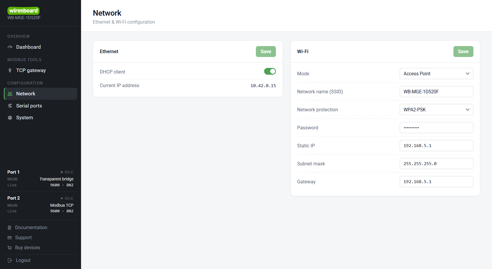 WB-MGE v.3 module settings, the obtained IP address 10.42.0.15
-
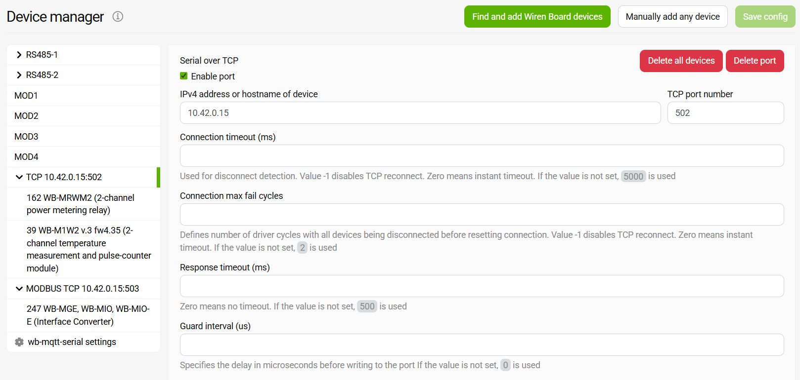 Port settings in wb-mqtt-serial
- Connect the Ethernet port of the module to a free Ethernet port of the controller.
- On the controller open Settings → Network Connections, select the connection of this port and in the IPv4 field select «Shared with other computers». The controller will start handing out IP addresses to the devices on this port.
- The network settings of the module do not need to be changed: the module will obtain an IP address from the controller via DHCP. Find it out in the web interface of the module (Configuration → Network).
The controller is connected to the module over Ethernet, the controller — IPv4 Static IP address, the module — Static IP address
-
Connection diagram
-
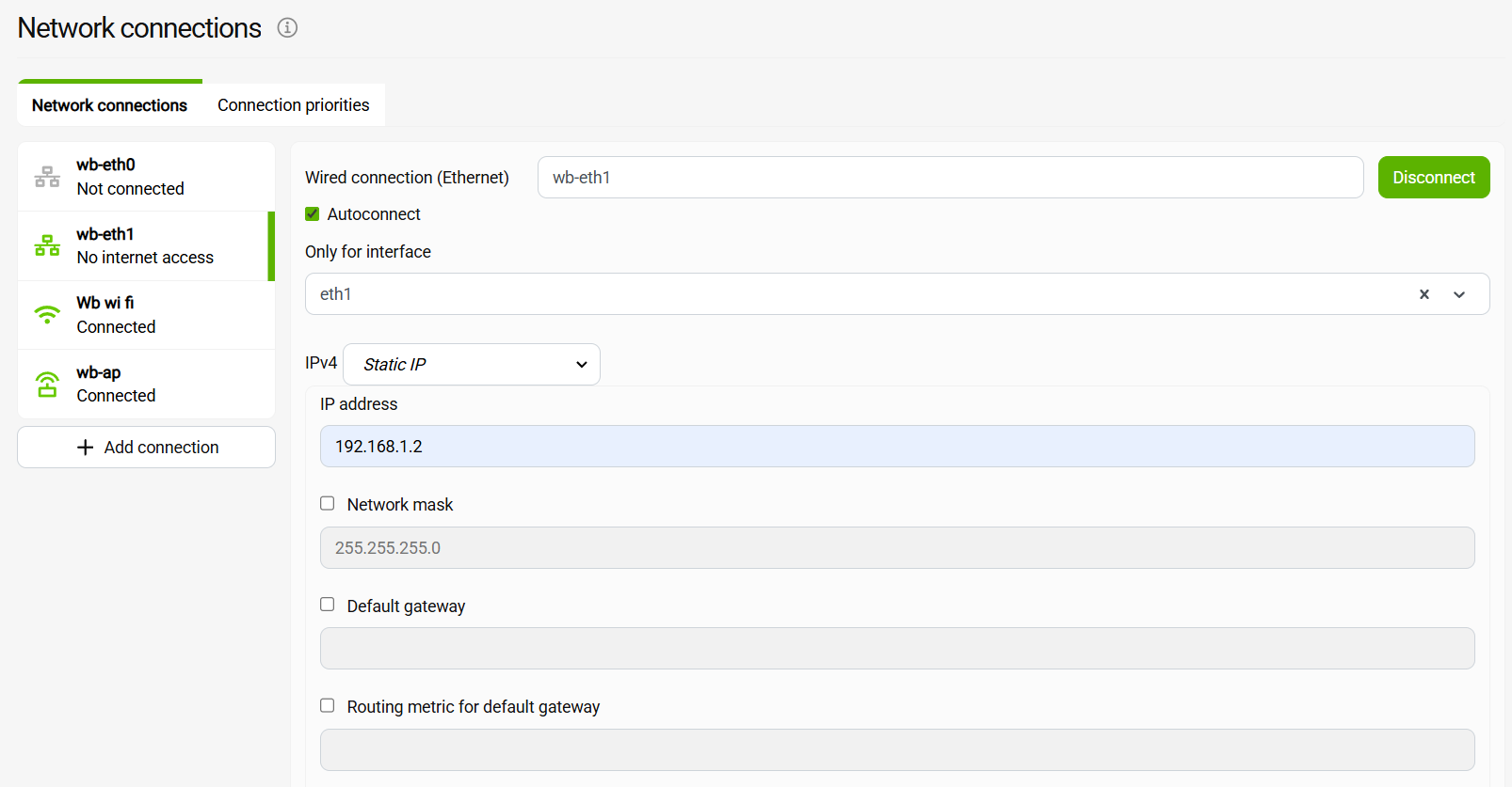 Configuring the Ethernet 2 port on the controller, Static IP address 192.168.1.2
-
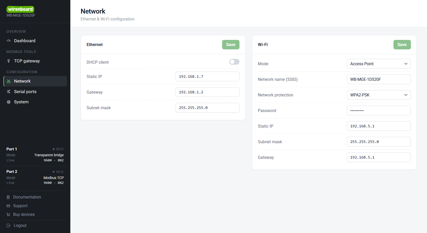 WB-MGE v.3 module settings, Static IP address 192.168.1.7
-
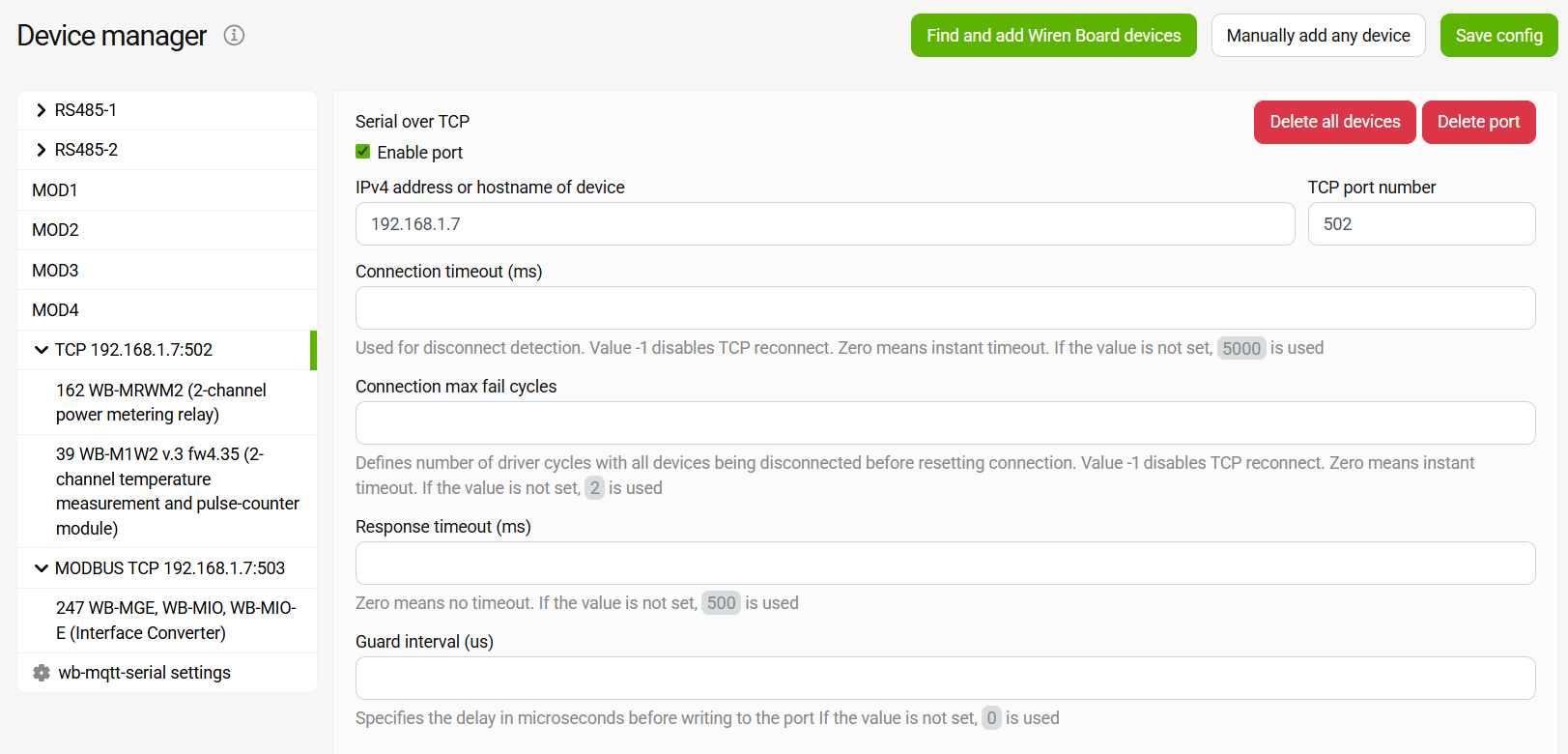 Port settings in wb-mqtt-serial
- Connect the Ethernet port of the module to a free Ethernet port of the controller.
- On the controller open Settings → Network Connections, select the connection of this port, in the IPv4 field select «Static IP address» and set the address and the subnet mask, for example,
192.168.1.2and255.255.255.0. - In the web interface of the module go to Configuration → Network → Ethernet, disable the DHCP client and set an IP address from the same subnet (for example,
192.168.1.7), the same mask and, in the Gateway field, the address of the controller.
To control the Modbus devices connected to the module from a Wiren Board controller, configure the wb-mqtt-serial driver as follows:
- In the settings of the wb-mqtt-serial driver add the TCP ports for receiving data from the RS-485-1 and RS-485-2 ports of the module. Specify the IP address of the module and the TCP port from the module's port settings in Modbus Tools → TCP gateway (by default 502 — RS-485-1, 503 — RS-485-2). The port type in the driver depends on the module port mode: for the «Modbus TCP» mode — Modbus TCP, for the «Transparent bridge» mode with the «Server» role — Serial over TCP.
- So that the devices appear on the Devices tab in the web interface of the Wiren Board controller, add them automatically, via scanning for Wiren Board devices on RS-485, or manually, by selecting a template.
- WBIO modules are added manually, by selecting a template. The address of a module depends on what the WB-MGE v.3 is used with:
- When using a Wiren Board controller:
<WB-MIO Modbus address>:<sequence number of the WBIO module (starting from 1)>. - When using a third-party controller or software: the addresses are calculated according to the WB-MIO register table.
- When using a Wiren Board controller:
If the devices do not respond, check whether the TCP ports in the settings of the module and of the driver match, and also the settings of the terminator and fail-safe biasing.
Firmware updates and resetting settings
- WB-MGE v.3 firmware changelog;
- Built-in WB-MIO firmware changelog.
Firmware update
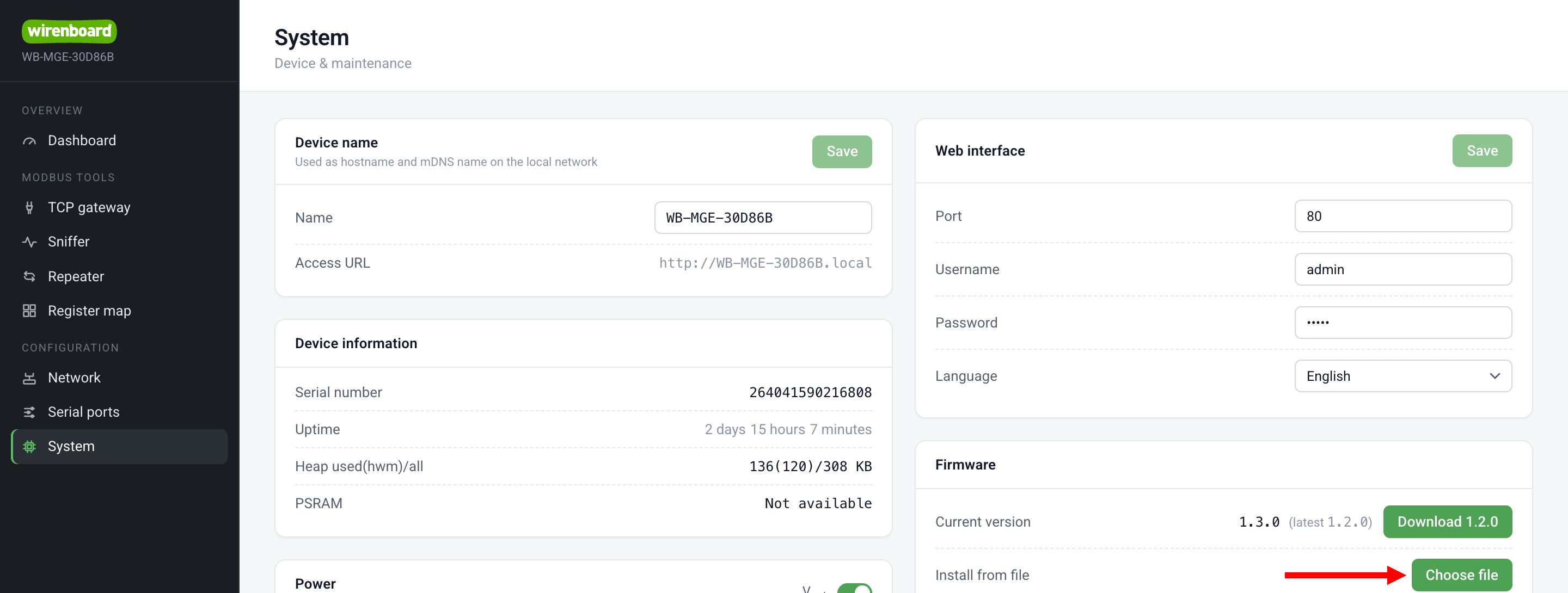
The update can be done from the web interface of the module:
- Download the latest firmware version. If the device sees an update, a download button appears next to the firmware version on the Overview and System pages — click it. Or download the file via the direct link latest.bin.
- Open the web interface of the WB-MGE v.3.
- Open the System page and locate the Firmware section.
- Click Choose file button, select the firmware file — the update will start automatically, wait for the process to finish.
After the firmware update the device will be rebooted.
Updating from a channel
Available from firmware 1.3.0
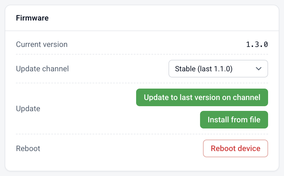
Starting with version 1.3.0 the module can download and install firmware on its own, without downloading a file by hand. On the System page, in the Firmware section, select Update channel:
- Stable — tested versions, the default channel;
- Testing — versions released ahead of the stable ones that are still being trialled.
The module finds out on its own which version is published in each channel and shows it right in the list: «Stable (last 1.1.0)», or «Testing (installed 1.3.0)» when the channel's version is already installed. The selected channel is stored on the device.
When the channel's version differs from the installed one, an Update to last version on channel button appears. On click the module asks for confirmation naming the version, then downloads the firmware from the cloud, installs it, reboots and checks that the expected version is the one now running — no file has to be downloaded or picked by hand. When the installed version matches the channel's version, the button is not shown.
The button installs the version published in the channel, which is not necessarily a newer one. If you are running a version from the testing channel and switch to stable, where an older version is published, the button will offer to install it — that is, to roll back. This is the regular way to return from a testing version to a stable one.
Updating from a file has not gone anywhere and works as before — the Install from file button is right next to it. It comes in handy for versions that are not in the channels, debug builds for example.
Restart
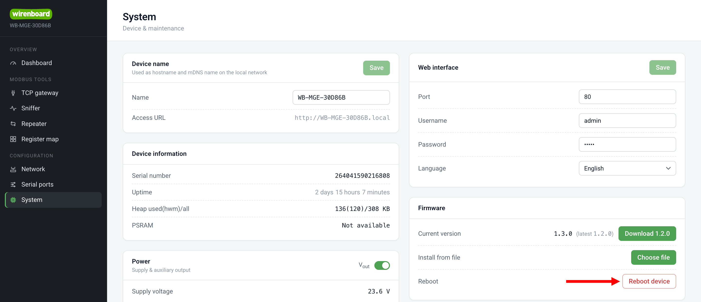
To reboot the device while keeping the settings, power it off for 10 seconds.
You can also use the Reboot button in the web interface on the System page.
Factory reset
From the web interface
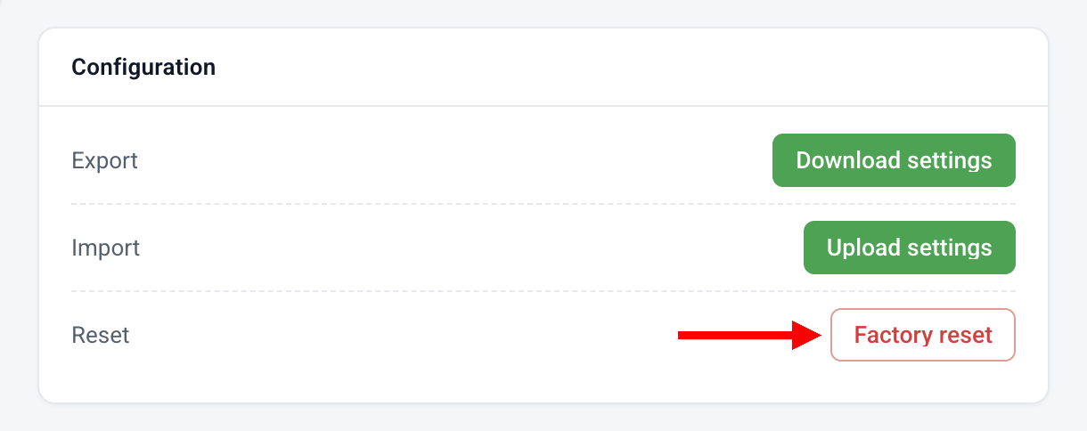
To reset the settings:
- Go to Configuration → System and locate the Configuration section.
- Click Reset button in the «Factory reset» row.
Using the Config button
To reset the settings the module has a Config button accessible through a hole in the front cover of the module. There are two ways — they differ in the depth of the reset and in whether a working main firmware is required.
- Factory reset (on a running device, without a reboot). Hold the Config button for 5 seconds with the power on: the firmware rewrites all settings to their default values and applies them immediately. Only the contents of the known settings are rewritten — the NVS partition itself is not erased. The confirmation is several rapid blinks of the Status indicator. The «Reset» button in the web interface gives the same result.
- Complete storage erase (via Factory mode). Needed when the main firmware does not start, or when everything has to be erased for certain. Apply power with the Config button held down to enter Factory mode, then hold the Config button for 5 seconds — the whole NVS partition is erased completely: all keys are deleted, including foreign and corrupted ones. After that the main firmware starts with clean factory settings. The confirmation is several rapid blinks of the Status indicator.
Factory mode
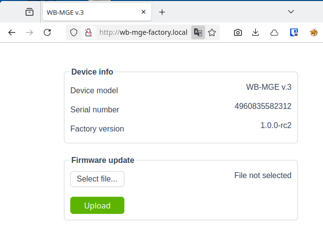
The mode is available only in a module with the factory firmware and serves to restore operation if the main firmware has not started for some reason.
To enable Factory mode apply power to the device with the Config button held down.
In this mode Ethernet is assigned the static IP address 192.168.0.7, the host name wb-mge-factory.local is set over mDNS, and instead of the web interface the module factory firmware upload form is shown.
Updating the integrated WB-MIO firmware
Wiren Board devices support firmware updates over Modbus. This allows bugs to be fixed at the installation site and, where technically possible, new features to be added. Settings stored in the device are retained during a firmware update.
Instructions:
- Firmware update ()
- Resetting settings
- Connection parameter settings
- Modbus address: find, reset or change
- Updating the bootloader
New firmware releases are listed in the Built-in WB-MIO firmware changelog.
Custom firmware and debugging
From the factory the module is flashed with the factory software that implements the gateway functions with the ability to update the firmware through the web interface. Nothing needs to be done to use the device as intended.
The gateway firmware is open source (MIT-WB license), repository: github.com/wirenboard/wb-mge.
Programming connector and debug console
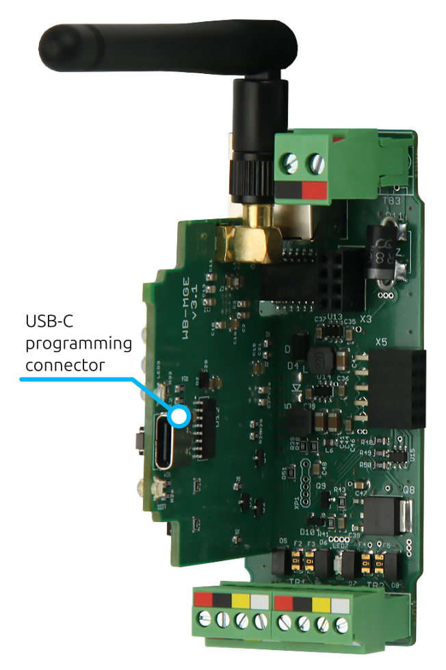
The module is based on the ESP32 chip, and a USB-C programming connector is installed on the board, so you can use the module hardware in your own firmware.
To access the USB-C connector you have to remove the top cover of the device by prying it off from the side with something thin. Debugging information can also be obtained from the module through this connector. When the module is connected to a computer over USB it is detected as an ACM device, which can be opened in any terminal program. In the debugging information you can find the SSID of the access point, the IP address assigned to the module over DHCP and so on.
Important: when using the debug console, first connect the USB-C cable to the computer and to the WB-MGE v.3, and only then apply power to the gateway. This will help avoid a reboot of the device, read more in ERRWB-MGEv30001.
Using custom firmware
If you are an enthusiast or a device developer, we have prepared instructions for flashing the device and examples of alternative firmware.
Known issues
WB-MGE v.3 hardware issues/caveats
Hardware revisions
Images and drawings
CorelDRAW 2018 (font: Ubuntu): File: WB-Library.cdr.zip
Visio:
- Wiren Board devices: File: WB-Visio-Lib.zip.
- Enclosures, circuit breakers, contactors and other third-party symbols.

Module dimensional drawing (DXF): WB-MGEv3.dxf.zip
Module dimensional drawing (PDF): WB-MGEv3.pdf
AutoCAD Electrical schematic symbol library: File: Wirenboard-AE-base.zip
-
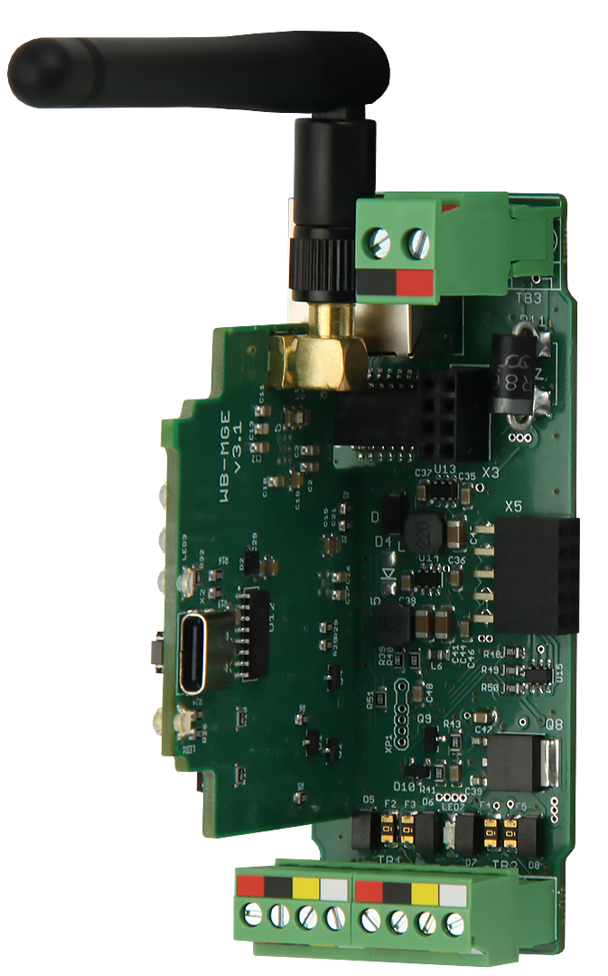 WB-MGE v.3 PCB
-
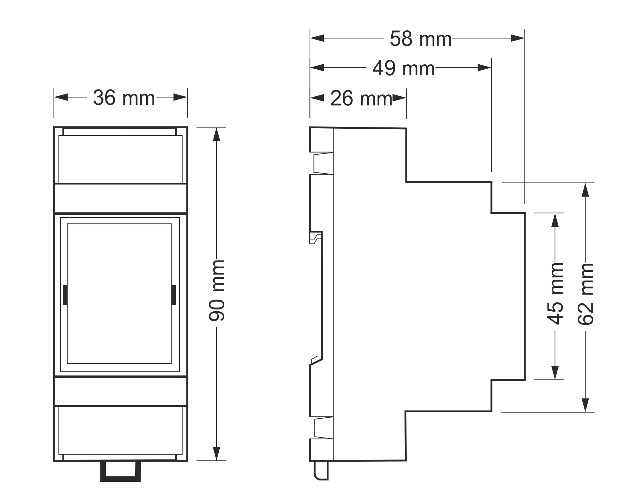 Overall dimensions
Third-party software components
The device firmware contains software components from the ESP-IDF project, distributed under the Apache License, version 2.0. The full text of the license is available in the ESP-IDF project repository. Shipped together with ESP-IDF are the cJSON parser under the MIT license and the Espressif components mdns and esp_io_expander under the Apache 2.0 license.
The web interface is built on the following libraries, all under the MIT license:
- Vue — the interface framework;
- Vue Router — routing between pages;
- Vue I18n — interface translations;
- vue-multiselect — dropdown lists with search;
- ky — the HTTP client;
- unhead — page titles.
The Roboto font is also used, under the SIL Open Font License 1.1.