 Documentation
Configuration with WB-MIO / WB-MIO-E
This guide translates the controller-configuration section for WBIO modules connected through a WB-MIO or WB-MIO-E interface converter.
Configuration in the Wiren Board controller
To control WBIO I/O modules connected to a WB-MIO(E) from a Wiren Board controller, configure the wb-mqtt-serial driver:
- Open the Wiren Board controller web interface.
- Go to Settings → Configs and select Serial device driver configuration.
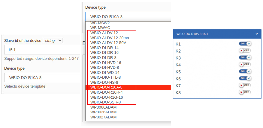
- Select the serial port to which the converter is connected and click Add any devices manually.
- Select the template for the connected WBIO module. Its name begins with
WBIO-…. - In Device address, enter the WBIO address as
<MIO Modbus address>:<WBIO sequence number>, for example15:1. - Click Save settings.
Addressing and communication
WB-MIO converts the WBIO module protocol to Modbus RTU. Each side module is addressed as <WB-MIO Modbus address>:<WBIO sequence number>. The converter's serial communication settings are configured through its registers.
The default serial settings are 9600 bit/s, 8 data bits, no parity, 2 stop bits. Each device on the RS-485 bus must have a unique Modbus address from 1 to 247. The factory-assigned address is printed on the enclosure label.
To display the converter itself on the controller's Devices page, use automatic RS-485 device discovery or add it manually with the WB-MGE, WB-MIO, WB-MIO-E (interface converter) template. Its widget shows the status and channel count of the connected side modules. Add the individual WBIO templates as described above to access their channels.
For a WB-MGE v.3 gateway, use the separate WB-MGE v.3 configuration guide.