 Documentation
WB-MGU
Multi-protocol gateway with WBE2 expansion modules
Covered order codes (1)
WB-MGU— Contact SmartSD for the required expansion module and PSRAM option
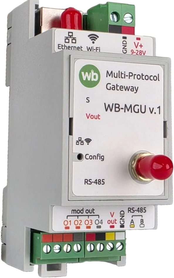
Purpose
Designed for connecting devices with an RS-485 interface to an automation server via Ethernet or Wi-Fi. The server can be any controller / computer that supports the required protocols.
The device has one RS-485 (Modbus RTU) port and one slot for WBE2 extension modules. Examples of such modules include wired interfaces such as isolated RS-485, CAN, KNX, OpenTherm and so on, or wireless interfaces such as Z-Wave LR, Zigbee or Matter. Extension modules communicate with the main ESP32 microcontroller via UART.
Two modes are available for the RS-485 port:
- Modbus TCP — for Modbus devices only;
- transparent gateway — suitable for any protocols running over RS-485.
The device comes flashed and ready to use as a gateway, but you can write your own firmware for it and use it for other tasks. Read more about developing DIY firmware.
Technical specifications
| Parameter | Value |
|---|---|
| General | |
| Microcontroller | ESP32 |
| CPU core | Xtensa® dual-core LX6, 32-bit, 240 MHz |
| Flash memory | 4 MB |
| SRAM | 520 KB |
| PSRAM | 0 MB (default), 8 MB (option) |
| Power supply | |
| Interface power supply voltage | 9 to 28 V DC |
| Power consumption at 24 V | 1 W |
| Maximum current from Vout | 2.5 A |
| Maximum current from Vout when powered by PoE (continuous) | 500 mA |
| Power inputs |
|
| Power input priority |
from the input with the higher voltage |
| Output for powering external devices | |
| Vout | The module supply voltage is output to the terminals, with overcurrent protection above 2.5 A and software shutdown.
When powered by PoE, a stabilized 24 V is supplied to Vout. When powered by PoE, the current available from Vout is lower. |
| Terminal blocks and wire cross-section | |
| Recommended wire cross-section with a sleeve terminal | 0.35 – 1 mm2 — single, 0.35 – 0.5 mm2 – double crimping |
| Length of a standard sleeve terminal | 8 mm |
| Screw tightening torque | 0.2 N∙m |
| Communication | |
| Data exchange protocol |
Via the RS-485 terminals:
|
| Interfaces |
|
| Operating conditions | |
| Air temperature | −40 to +70 °C |
| Relative humidity | Up to 95%, non-condensing |
| Climatic execution according to GOST 15150-69 | O2.1* |
| Warranty period | 2 years |
| Service life | 5 years |
| Dimensions | |
| Width, DIN units | 2 |
| Overall dimensions (L x W x H) | 36 x 90 x 58 mm |
| Weight (with packaging) |
105 g |
General operating principle
Hardware
The module is based on the ESP32 chip, which implements the functions of an RS-485 gateway, allows controlling peripherals and indicators, and provides a web interface and API for configuring the module.
Network interfaces and packet handling
The module has two network interfaces: Ethernet and Wi-Fi, which can act as an access point or client.
The module firmware receives packets via Ethernet / Wi-Fi and sends them to the RS-485 port or to the WBE2 extension module port, then relays the device responses back. The port is selected by the TCP port the packet arrived on, default: 502 — RS485-1, 503 — RS485-2.
Power supply
The module can be powered in two ways: directly from the Vin terminal or, optionally, via IEEE 802.3af / 802.3at standard PoE.
Powering via PoE requires a separate WBP-ACTIVE-POE module with a built-in voltage converter, which is installed inside the device. It converts the input PoE voltage to 24 V and supplies it to the gateway's internal power bus.
Using the WBP-PASSIVE-POE module is permitted, but only with a power supply voltage not exceeding 24 V DC. Exceeding this voltage will result in the gateway failure.
The module is equipped with one power output (Vout) for connecting peripheral devices.
| Connected load power | Vin (24 V) | Active PoE mode | Passive PoE mode | |
|---|---|---|---|---|
| 802.3af | 802.3at | |||
| Nominal | 60 W | 15 W | ||
| Maximum short-term | 120 W | 12 W | 28 W | 30 W |
Indication
On the front panel under the sticker, there are indicators showing the status of the module and its outputs.
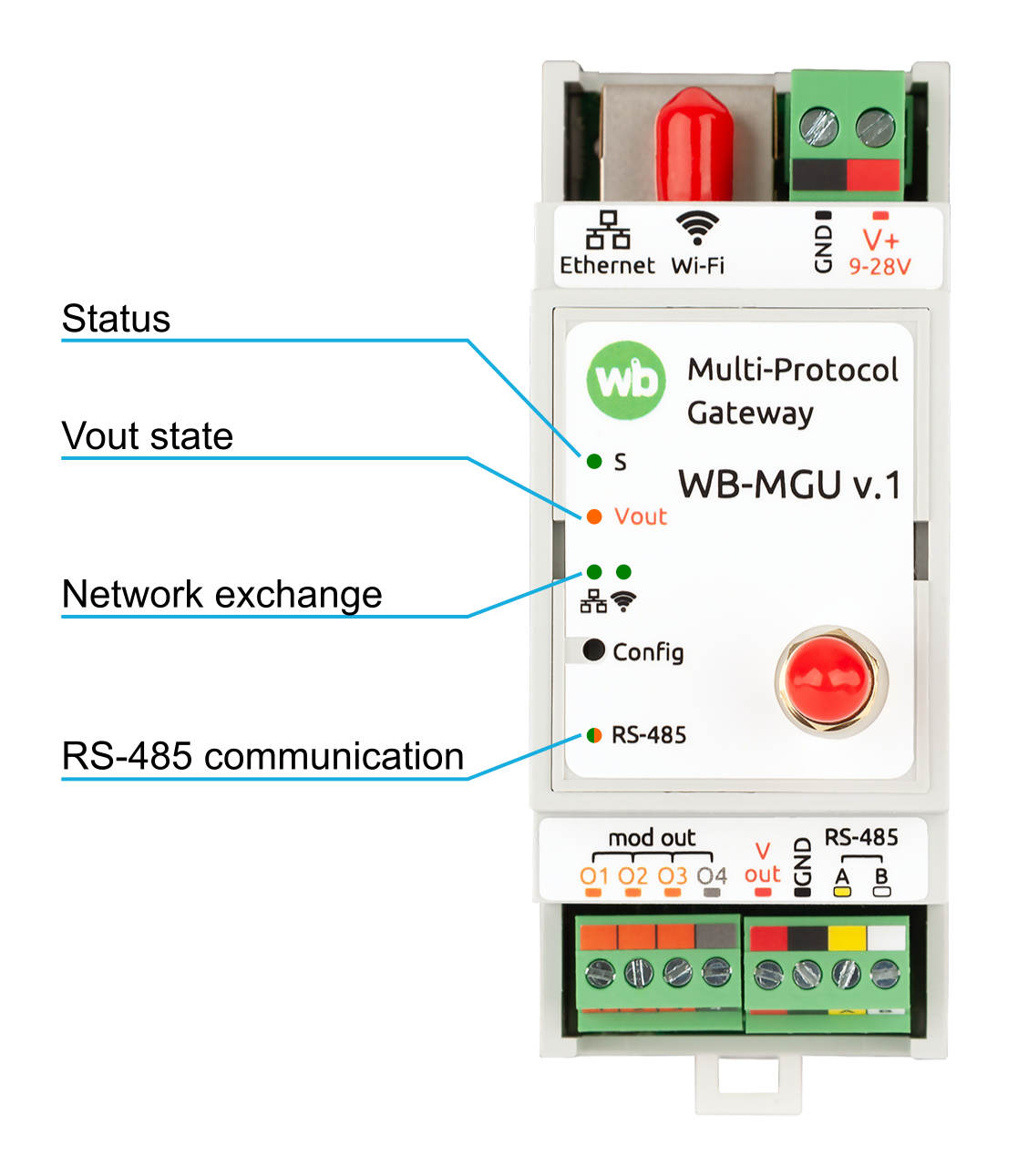
| Label | Color | State | Meaning |
|---|---|---|---|
| Status | Green | blinking | the device has booted and is operating normally |
| on | power is present, firmware problem | ||
| Vout | Orange | on | power to devices is ON |
| off | power to devices is OFF | ||
| Ethernet | Green | on | link is up |
| blinking | data exchange | ||
| off | no link | ||
| Wi-Fi | Green | on | enabled, no data exchange |
| blinking | data exchange | ||
| off | disabled | ||
| RS-485 | Green (RX) | blinking | receiving data from the port |
| Orange (TX) | blinking | sending data to the port |
Installation
WB-MGU is mounted on a standard 35 mm DIN rail and occupies a width of 2 DIN modules.
Wiring
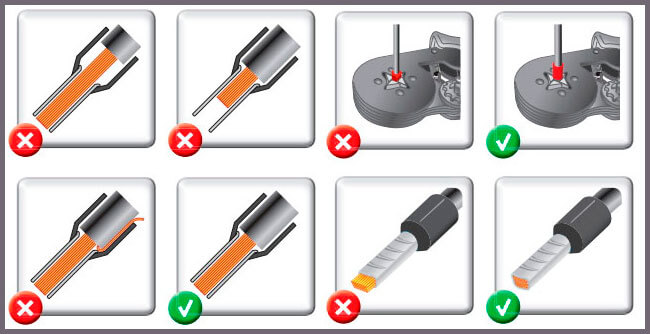
We recommend using flexible multi-strand wires with the ends crimped using sleeve terminals.
When stripping the insulation, the wire should be stripped exactly to the length of the sleeve (you can strip more and then cut off the protruding excess). For crimping, use crimping pliers (crimper). During installation, the wire crimped with a terminal is not damaged by the screw clamp and is securely fastened.
Do not apply excessive force when tightening the terminal—this will damage the screw connection.
Module power supply
The V+ GND terminal block with a 5.08 mm pitch is used for power connection.
The module can also be powered by Ethernet PoE.
Network interfaces
The module is connected to the Wiren Board controller or another device directly via Ethernet or via Wi-Fi, including through a router or VPN. The main condition is that the module's IP address must be accessible from the controller.
RS-485
The V+ GND A B terminal block with a 3.5 mm pitch is used to connect devices via the RS-485 bus. Power for the connected devices can also be taken from these terminals. For stable communication with the device, it is important to correctly organize the connection to the RS-485 bus; read about this in the article RS-485 Bus Physical Connection.
For the RS-485 interface, settings for speed, stop bits, and other parameters are available. By default, the terminating resistor and failsafe bias are enabled. They can be disabled in the settings. The RS-485 ground in the WB-MGU is not isolated from the power ground.
Configuration
Web interface
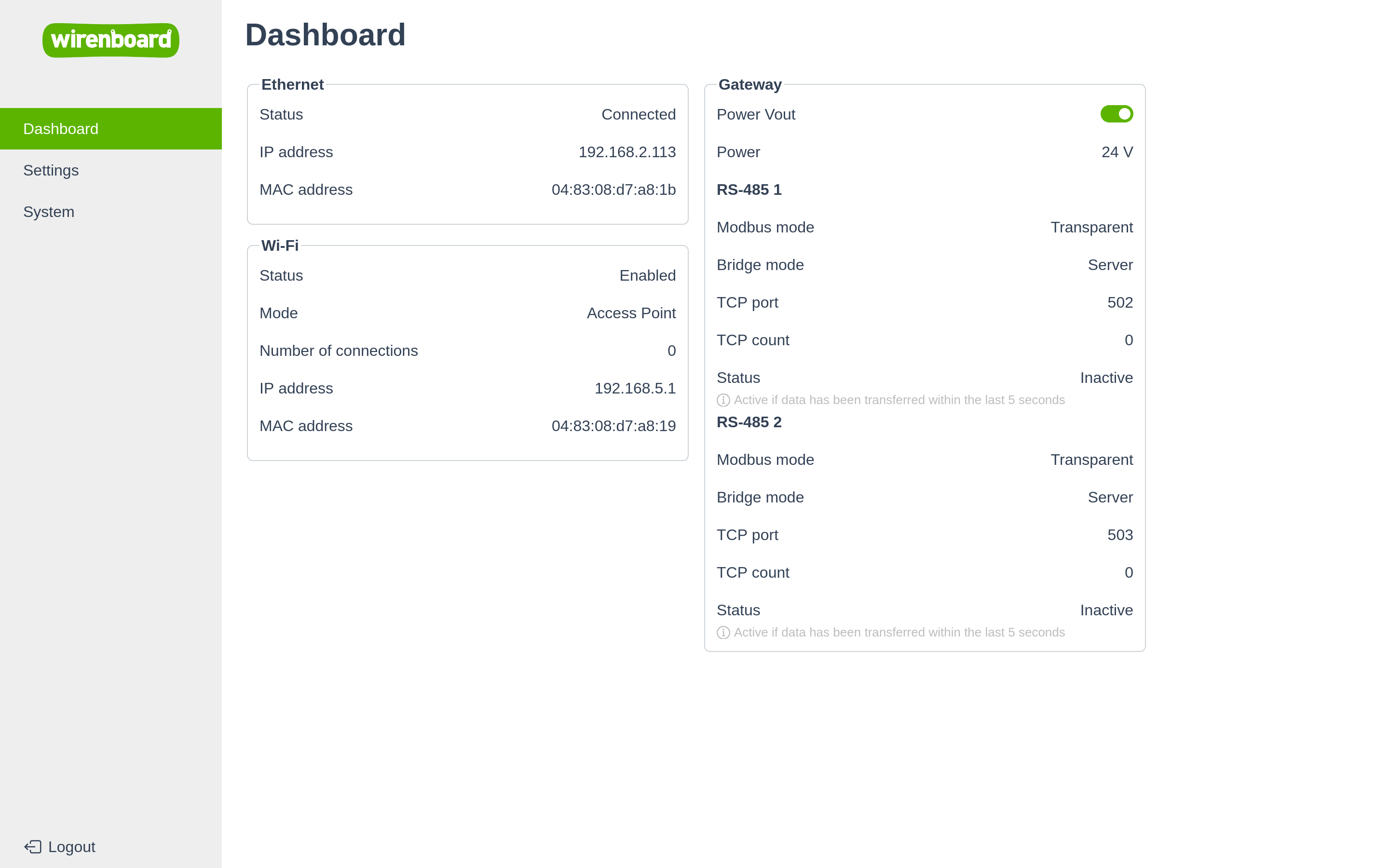
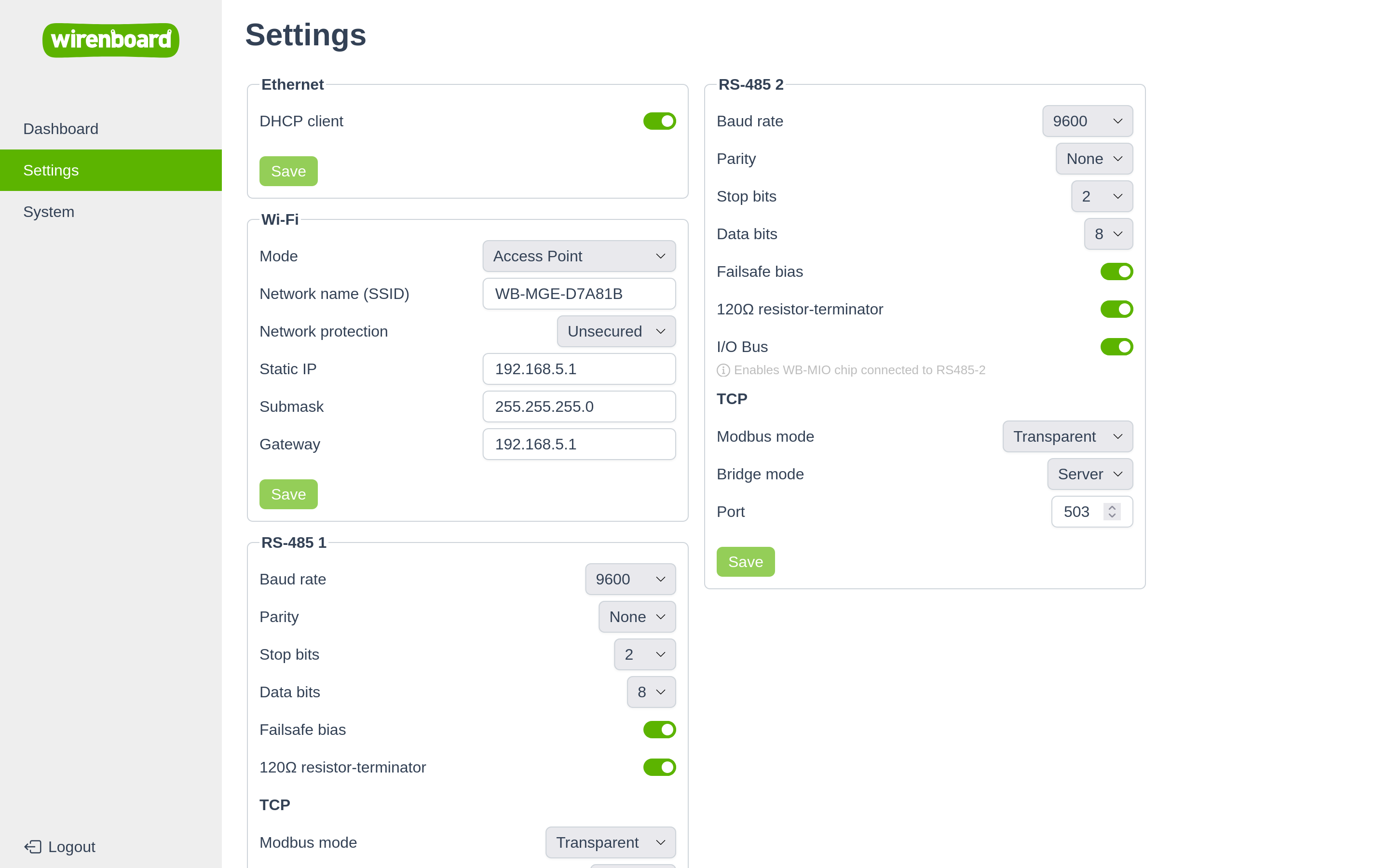
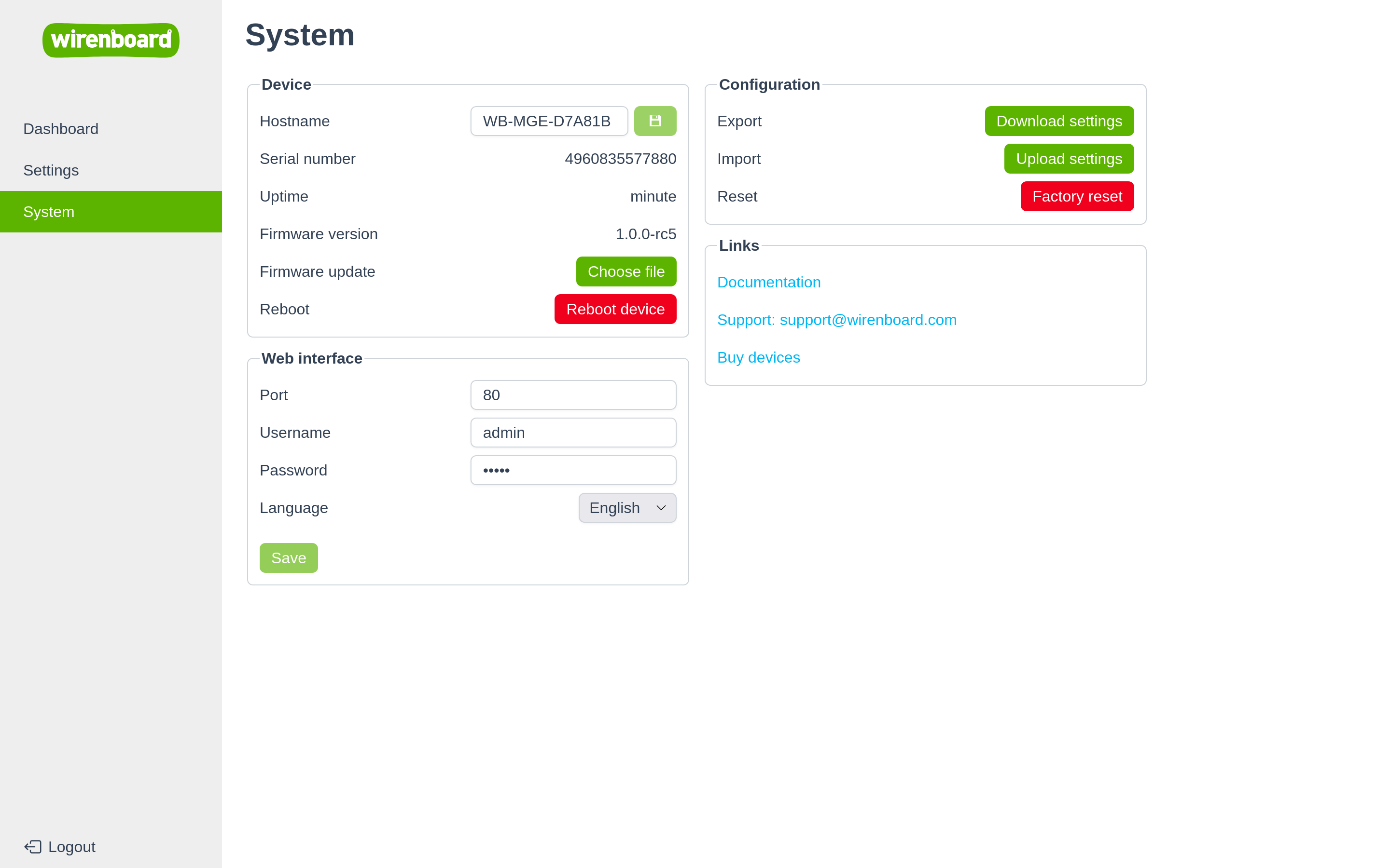
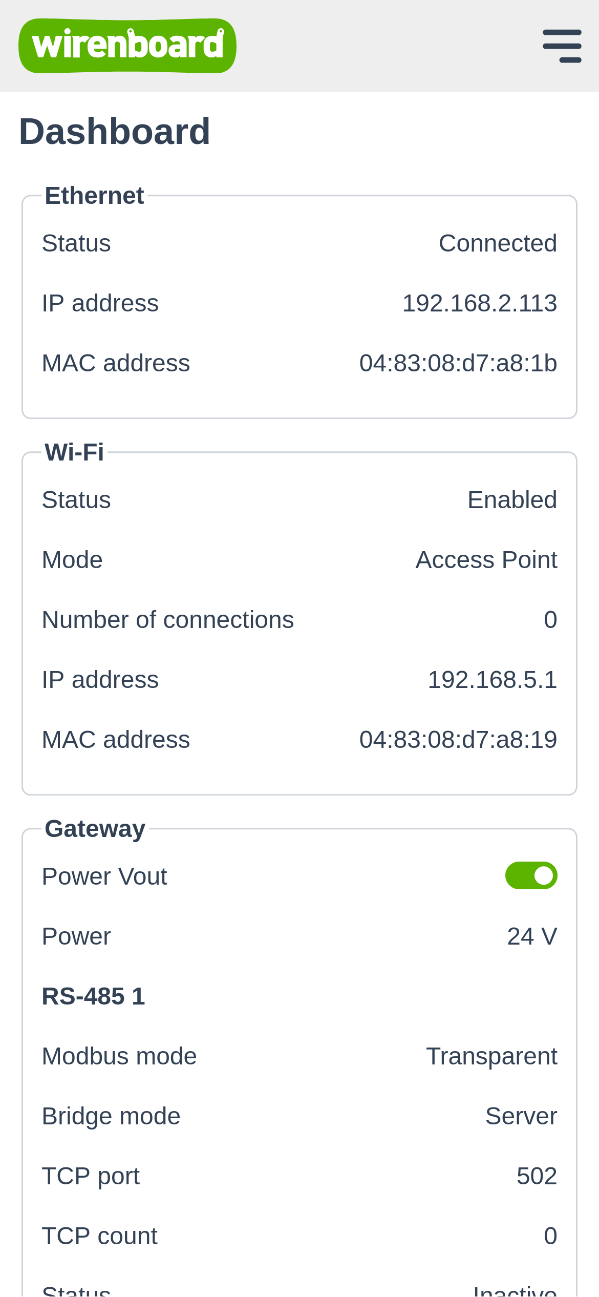
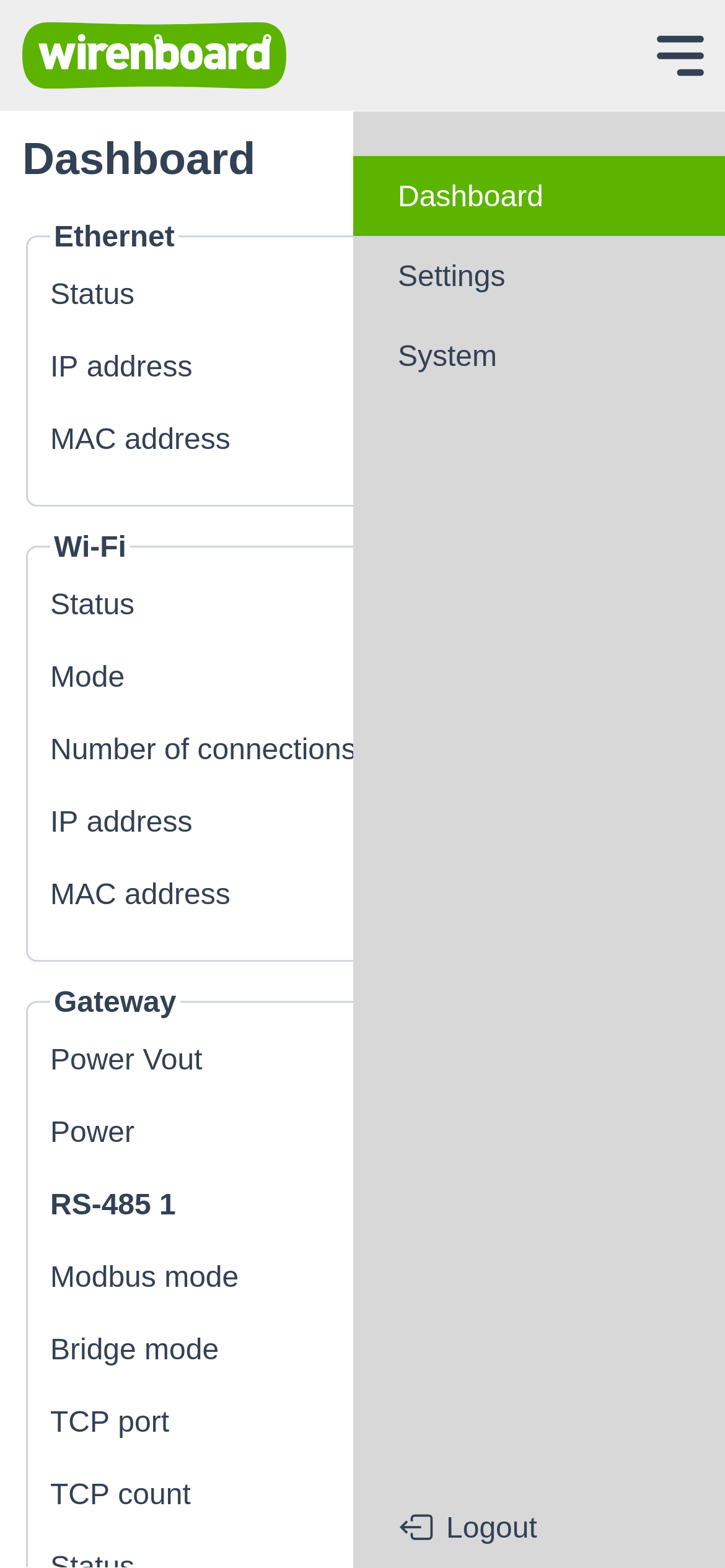
For convenience of settings, the module has a web interface that works in modern browsers on computers and mobile phones. To access it, you need to connect the computer and the module to the same network via one of the interfaces:
- Wi-Fi, where it brings up an access point and automatically distributes IP addresses to clients.
- Ethernet, where IP addresses are not configured; the module must receive them via DHCP, for example, from your router.
Default values are given in the table below. More information about network settings is output to the debug console accessible via the USB-C port under the module cover.
- Web interface screenshots
-
-
-
-
-
-
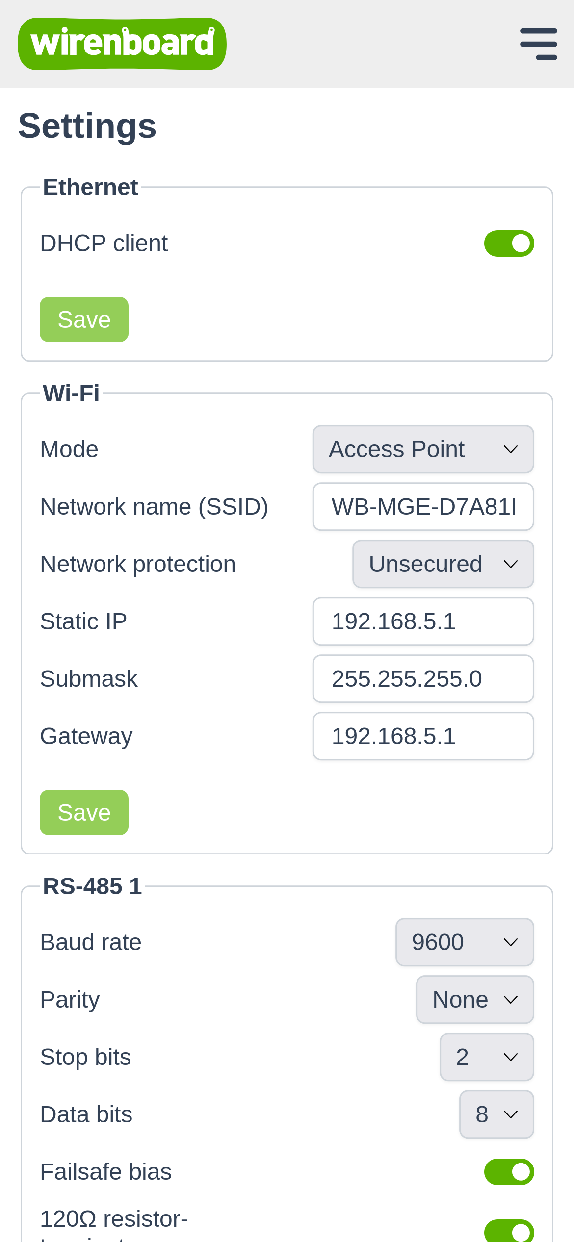
| General | |
|---|---|
| Login | admin |
| Password | admin |
| mDNS hostname | wb-mgu-XXXXXX.local, XXXXXX — the last 3 bytes of the Ethernet MAC in hex
You can also take the access point name printed on the sticker and append .local to it |
| Wi-Fi | |
| Access point | WB-MGU-XXXXXX, XXXXXX — the last 3 bytes of the Ethernet MAC in hex. |
| Key (password) | printed on the sticker on the side of the device. |
| IP address | 192.168.5.1 |
| Subnet mask | 255.255.255.0 |
| Ethernet | |
| IP address | DHCP |
| Subnet mask | DHCP |
Web interface access
Access to the module web interface via the Wi-Fi access point
By default, Wi-Fi operates in access point mode:
- On your laptop or phone, open the list of Wi-Fi access points and connect to WB-MGU-XXXXXX, where XXXXXX are the last 3 bytes of the Ethernet MAC in hex.
- Enter the security key (password) printed on the sticker on the side of the device.
- The web interface is available at 192.168.5.1, login / password — admin / admin.
Access to the module web interface via Ethernet
By default, the module Ethernet port is set to obtain an IP address via DHCP, so you need a router that assigns IP addresses — usually any router in a home or office will do:
- Connect the module to the router via Ethernet.
- Open your router settings and find the IP address it assigned to the module.
- Open a web browser on a computer connected to the same router. The web interface is available at the IP address from the previous step, login / password — admin / admin.
Access to the module's web interface via Wiren Board Cloud
If the WB-MGU is connected to one of the controller's network interfaces, and the controller is in the Wiren Board Cloud, you can configure proxying for the module's web interface and access it via the cloud. Details in Gaining access to arbitrary web interfaces on the controller.
Saving and loading configuration
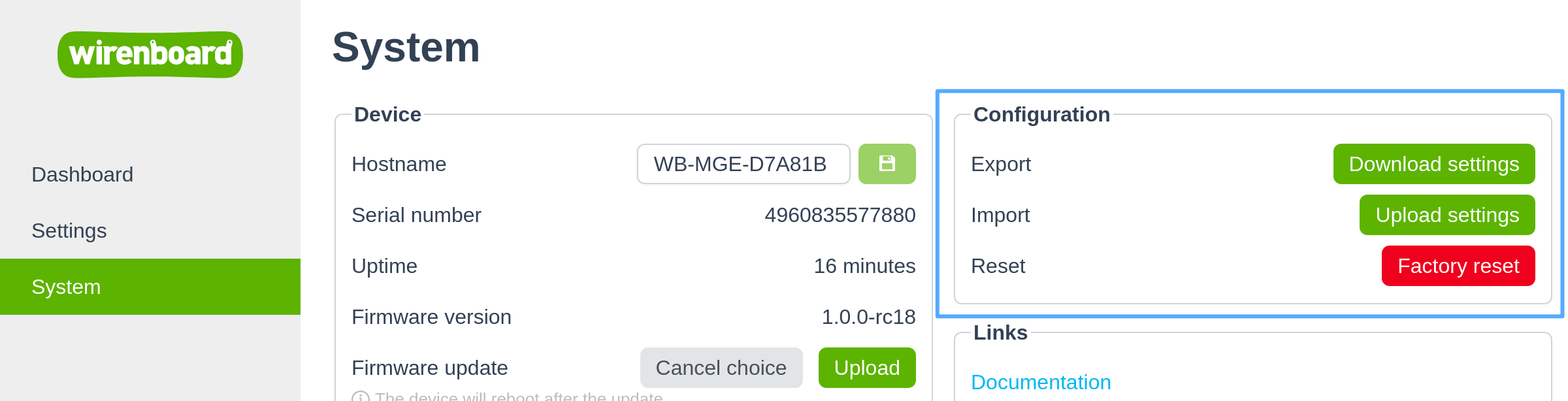
Configured parameters can be saved to a file and used to restore them on a new device or when creating identical installations.
All web interface, port, and network interface settings are exported to the file.
Terminator and failsafe bias
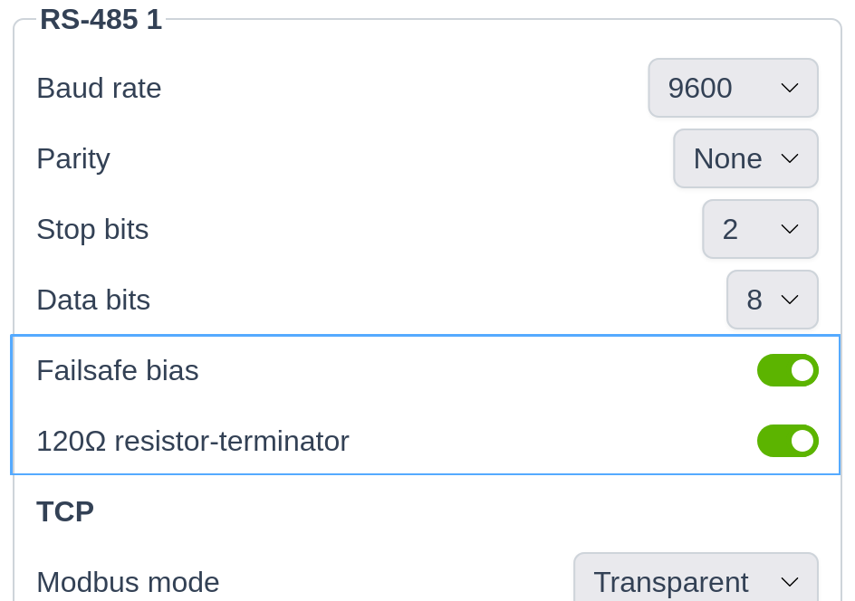
The module has the following installed and enabled by default:
- terminator — a 120 Ohm resistor between lines A and B. Enable it if the module is at the end of the bus, disable it if the module is in the middle.
- failsafe bias — 560 Ohm resistors that bias the bus, removing the undefined state when the device transmitters are off. Enable it if the module works as the master, disable it otherwise.
Control is done in software: go to the settings of the required port and enable or disable the corresponding resistor as needed.
«Modbus TCP» mode
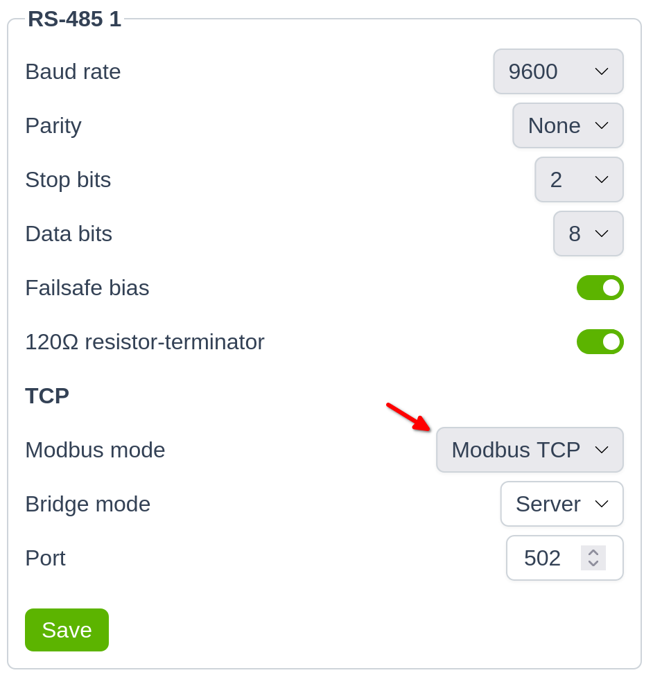
In this mode, the module receives Modbus TCP packets via network interfaces, unpacks them, and sends them to one of the RS-485 ports. Then it packs the received response and sends it back to the network interface to the client that requested the data.
Mode selection is available for each port separately:
- Go to Settings → RS-485 1 (or 2).
- Select the Modbus TCP mode.
- If needed, set the TCP port whose requests will be forwarded to this RS-485 port.
In Modbus TCP mode, the module can only act as a server. Currently, only one simultaneous connection is supported per port.
«Transparent gateway» mode
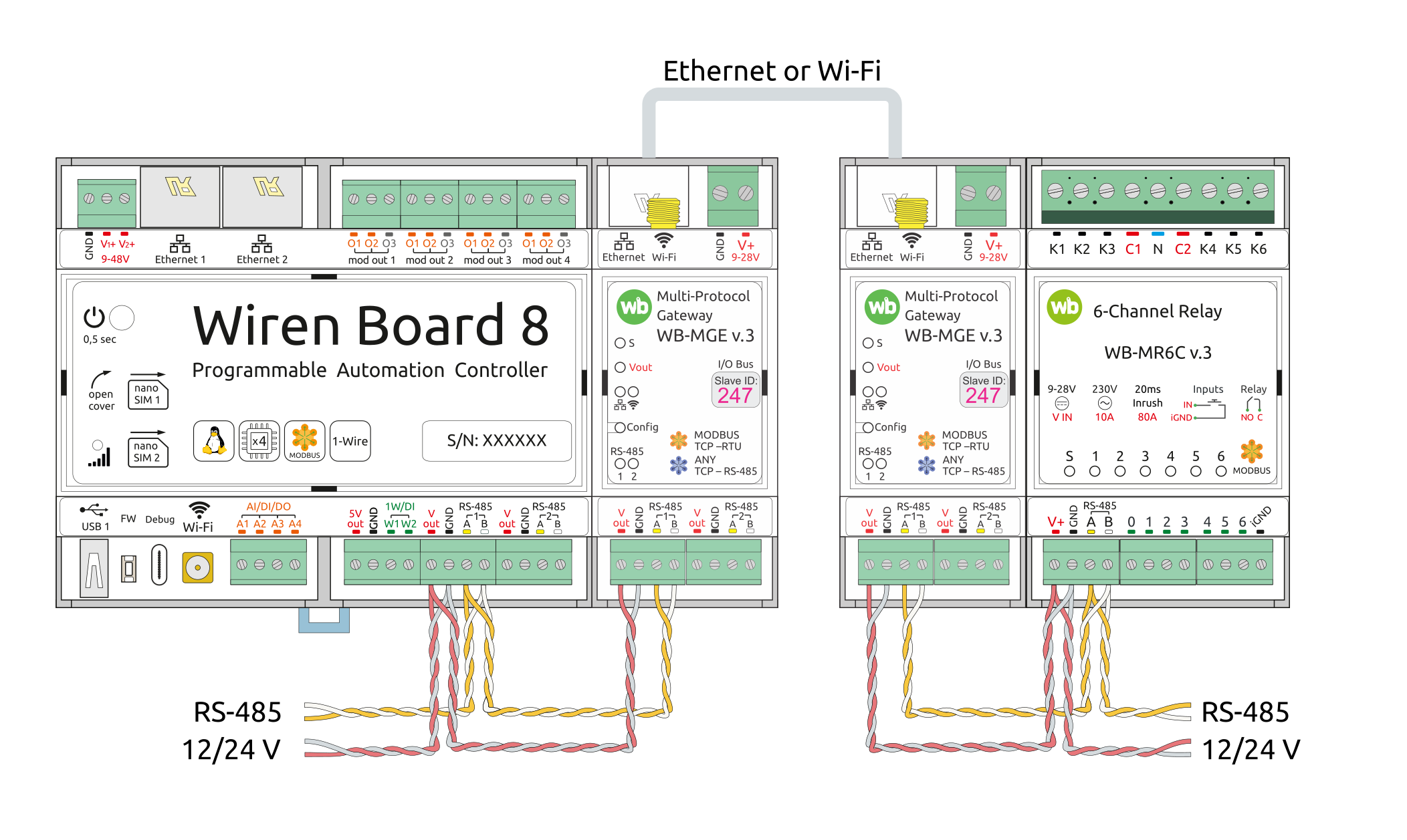
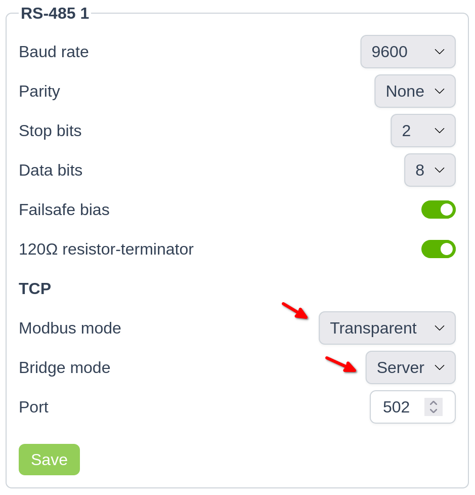
In this mode, the module receives packets of any protocol (for example, Modbus over TCP) via its network interfaces, unpacks them and sends them to one of the RS-485 ports. Then it packs the received response and sends it back to the network interface the request came from.
Mode selection is available for each port separately:
- Go to Settings → RS-485 1 (or 2).
- Select the Transparent mode and choose a role.
- If needed, set the TCP port whose requests will be forwarded to this RS-485 port.
The following roles are available in «Transparent gateway» mode:
- Server — used when, for example, a Wiren Board controller connects to it.
- Client — used when the WB-MGU connects to another similar module.
In this mode, only one master can poll devices on each port.
If you want to bridge two RS-485 bus segments over a local network or VPN using WB-MGU, select the «Server» mode for one module and the «Client» mode for the other, and specify the server IP address.
When joining two RS-485 bus segments with WB-MGU gateways and polling the devices from a Wiren Board controller, set the timeout in the port settings of the wb-mqtt-serial driver to at least 200…250 ms over Ethernet or at least 350 ms over Wi-Fi or VPN.
Configuration in the Wiren Board controller
The controller and the module are connected to the same network via a router and obtain IP addresses via DHCP
-
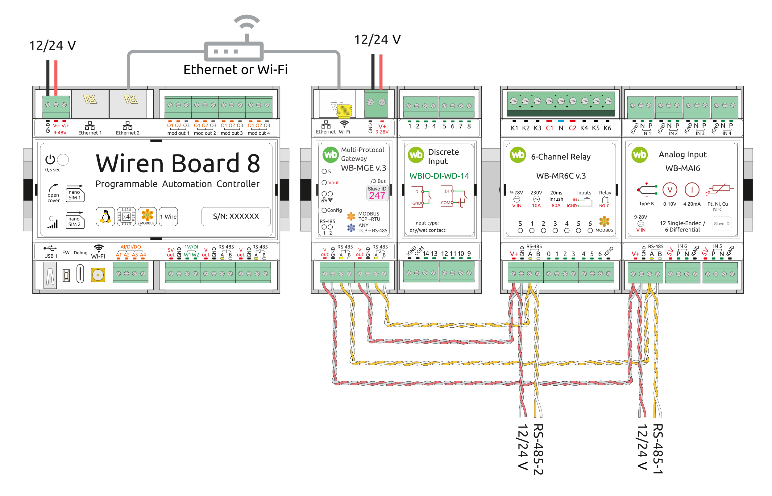 Connection diagram
-
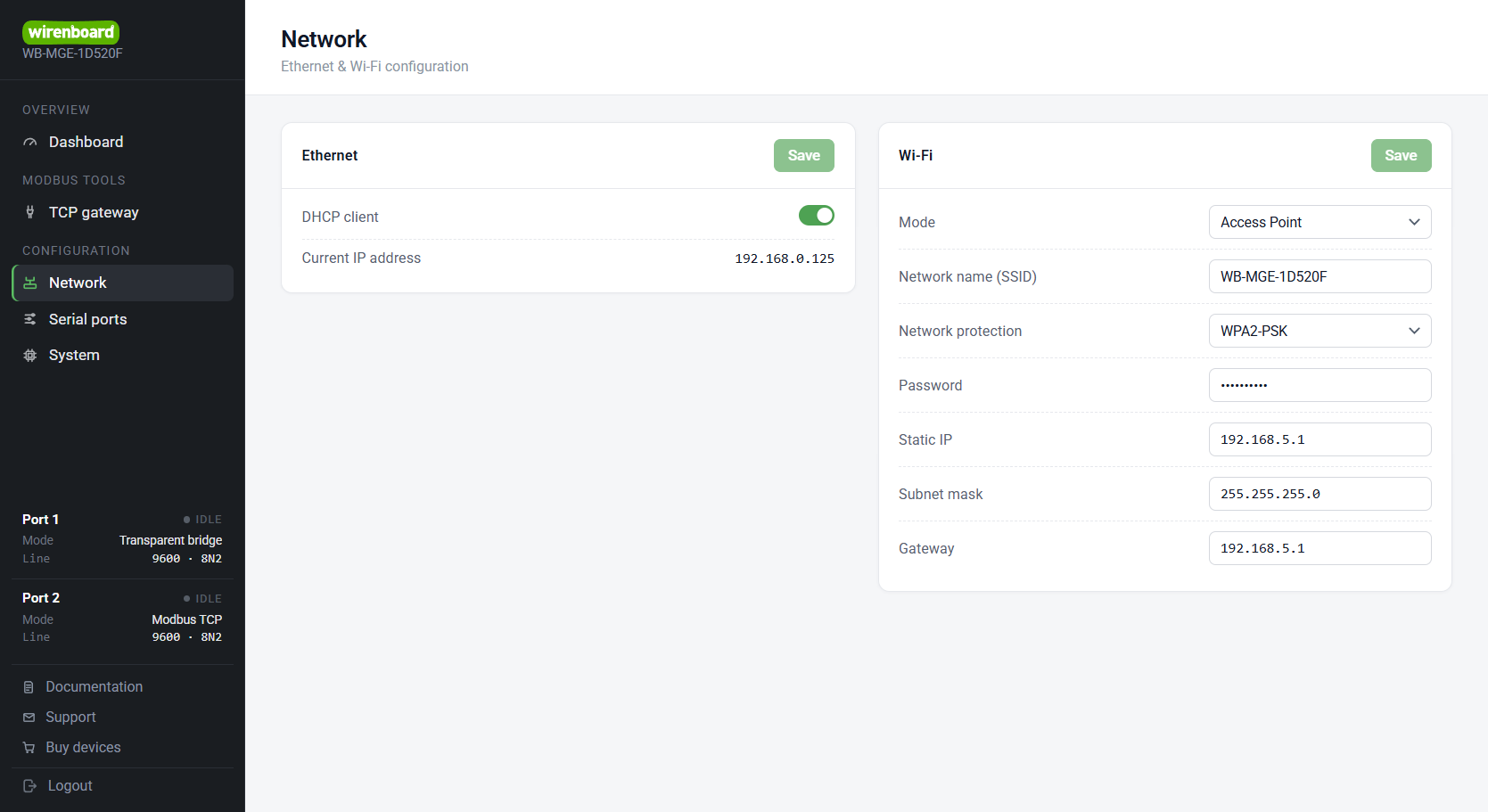 WB-MGU module settings, obtained IP address 192.168.0.196
-
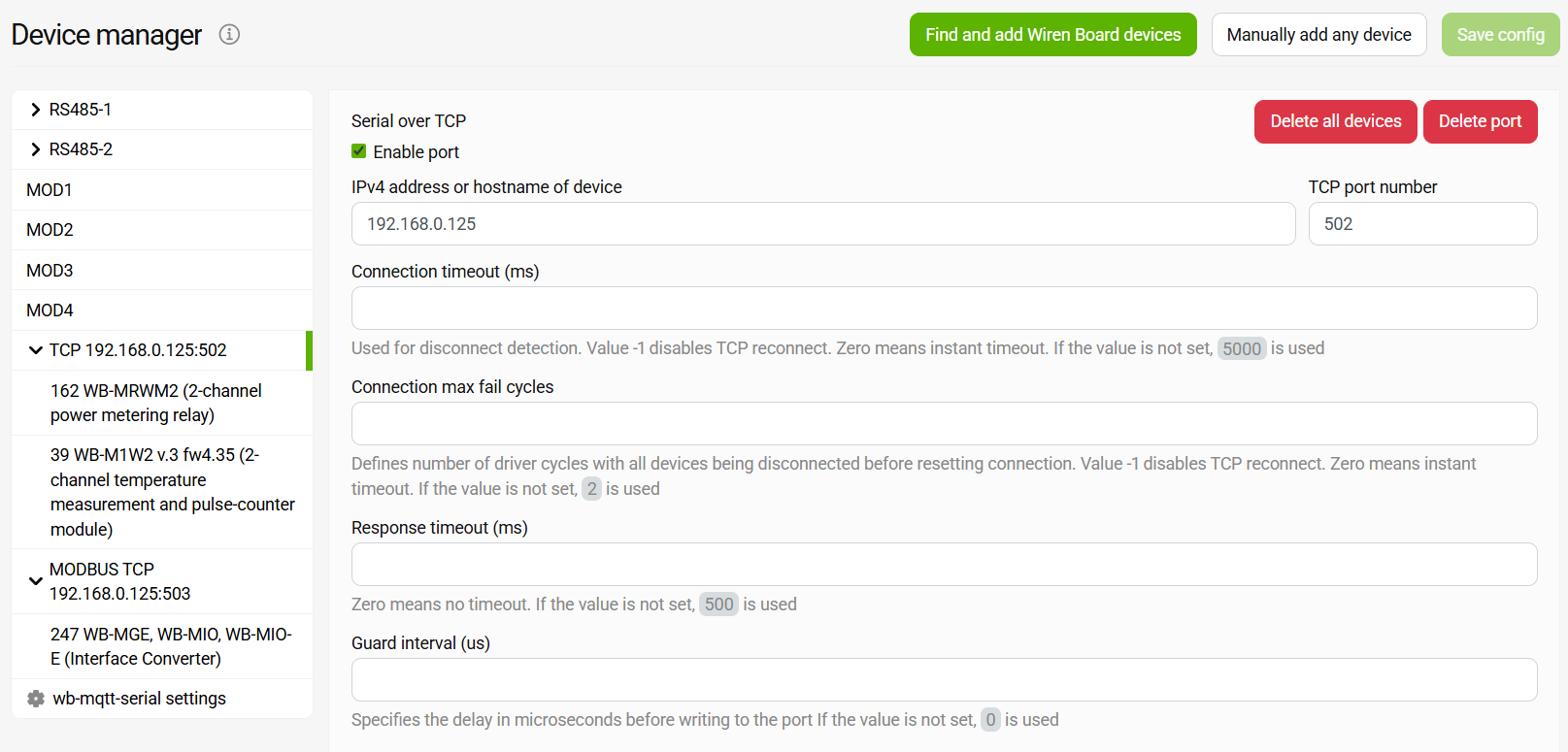 Port settings in wb-mqtt-serial
The controller is connected to the module via Ethernet, the controller — IPv4 Shared with other computers, the module — DHCP Client
-
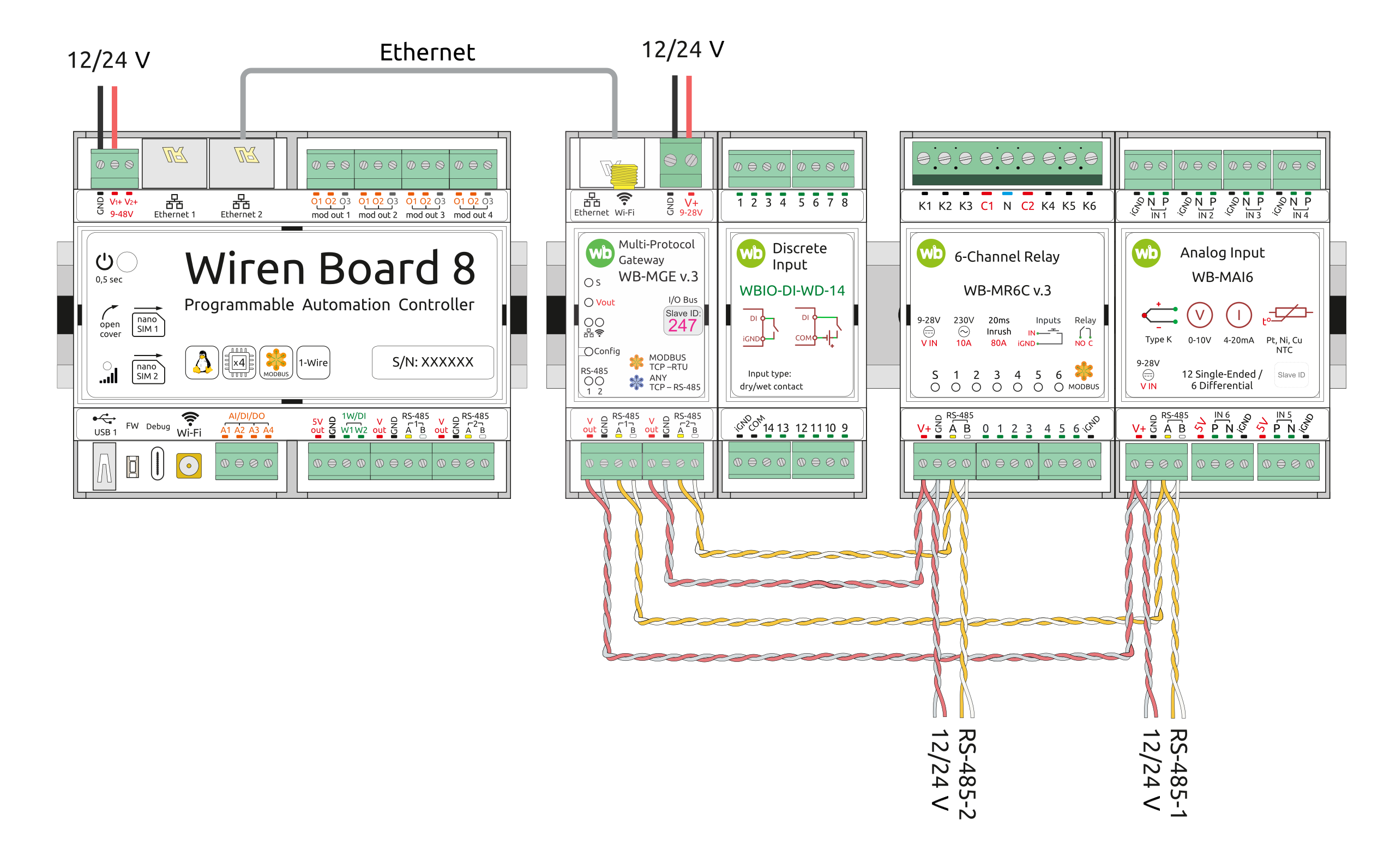 Connection diagram
-
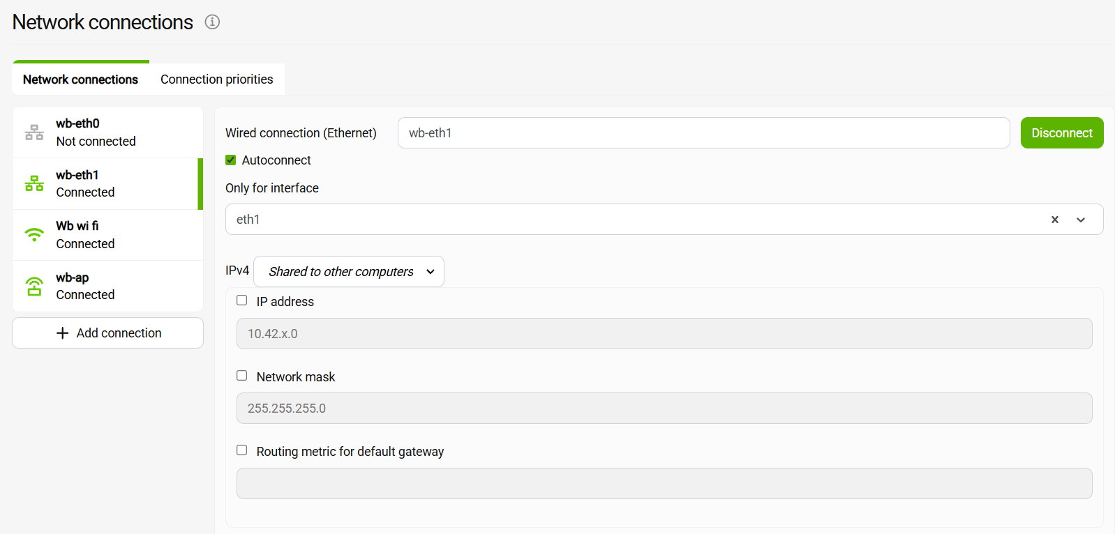 Configuring the Ethernet 2 port on the controller
-
WB-MGU module settings, obtained IP address 10.42.0.176
-
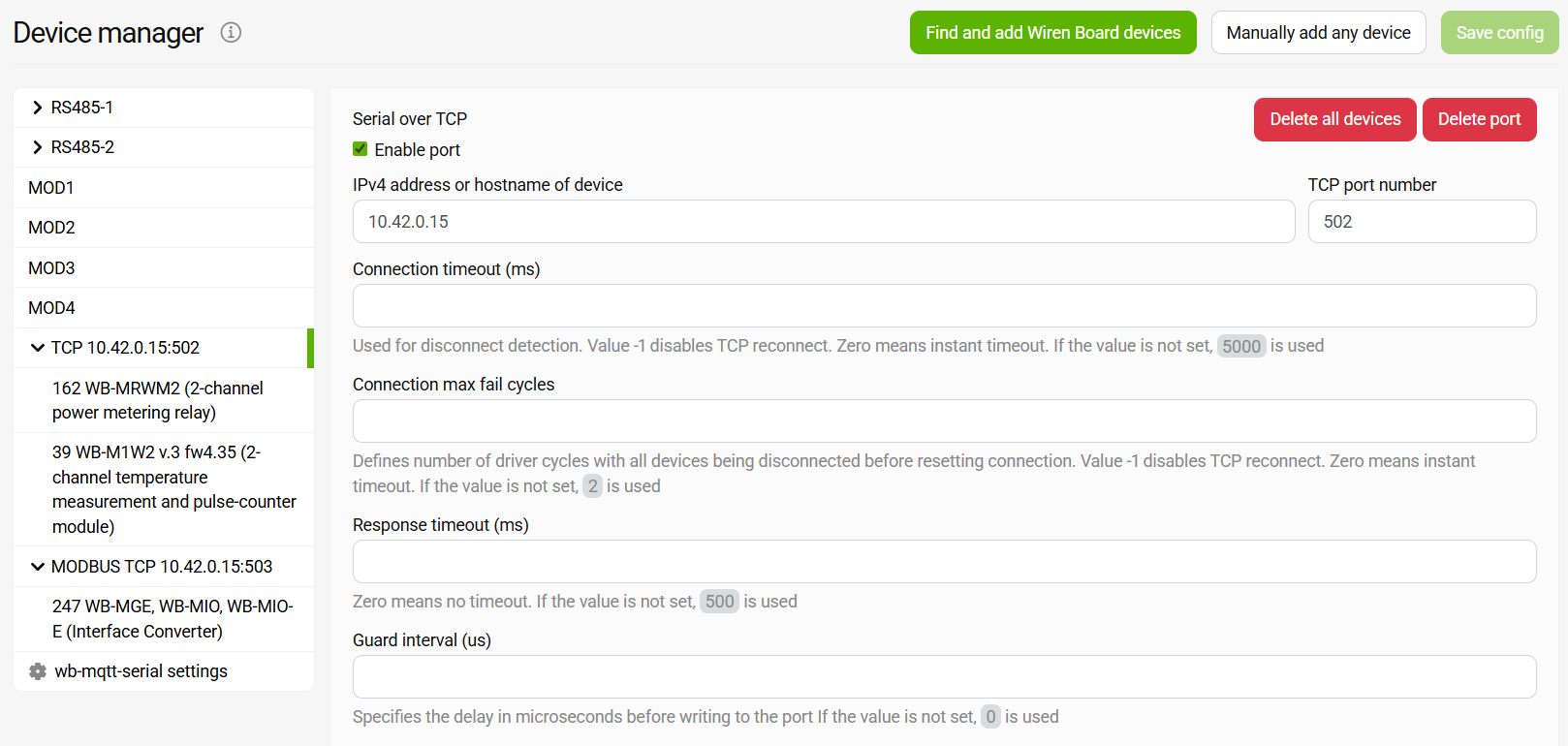 Port settings in wb-mqtt-serial
The controller is connected to the module via Ethernet, the controller — IPv4 Static IP address, the module — Static IP address
-
Connection diagram
-
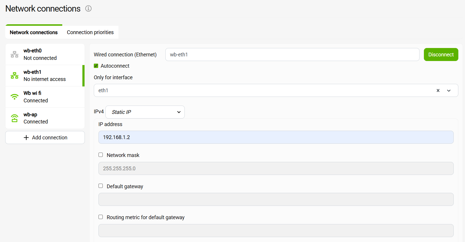 Configuring the Ethernet 2 port on the controller
-
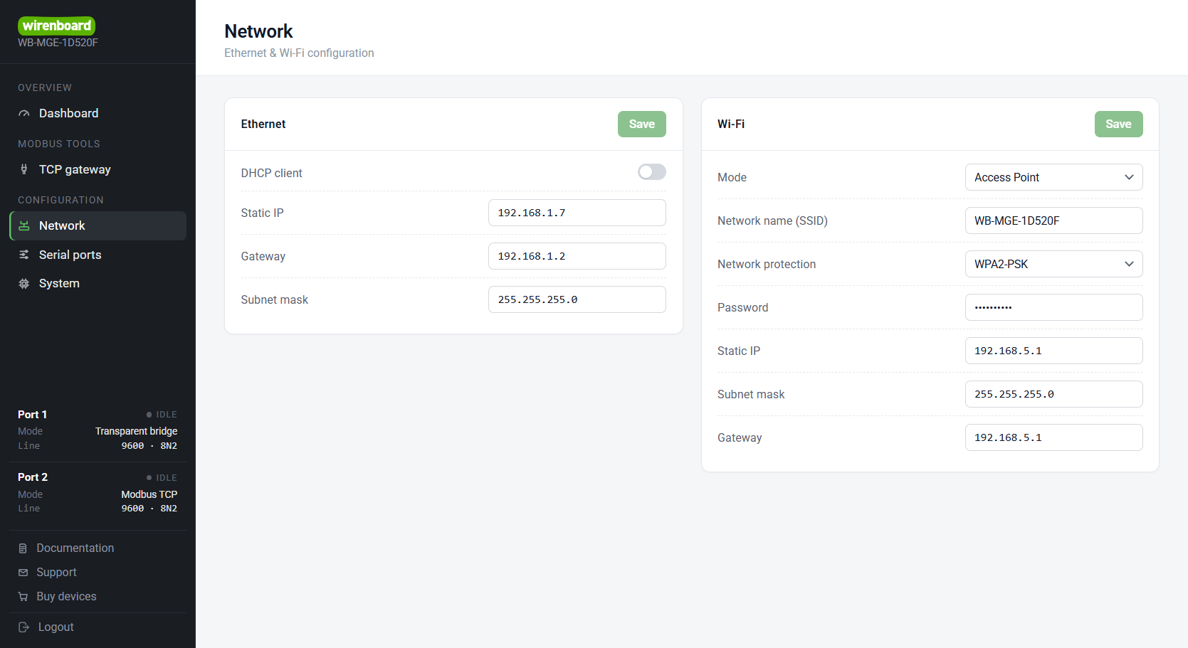 WB-MGU module settings, static IP address 192.168.1.7
-
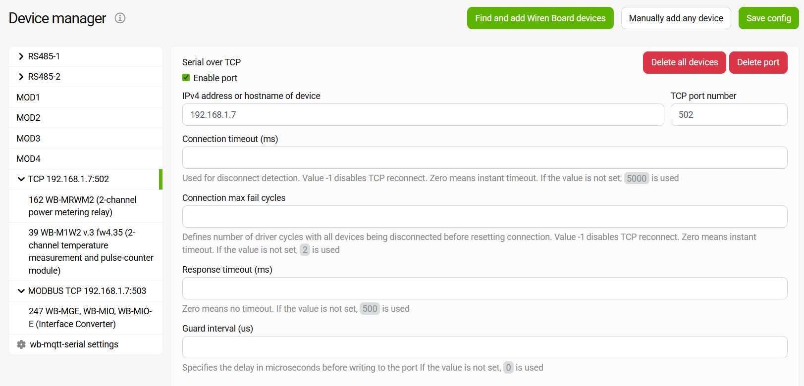 Port settings in wb-mqtt-serial
To control the Modbus devices connected to the module from a Wiren Board controller, configure the wb-mqtt-serial driver:
- In the wb-mqtt-serial driver settings, add TCP ports to receive data from RS-485-1 and RS-485-2 of the module.
- To make the devices appear on the Devices tab of the Wiren Board controller web interface, add them automatically via Wiren Board device search on the RS-485 bus or manually by selecting a template.
- WBIO modules are added manually by selecting a template. The module address depends on what the WB-MGU is used with:
- Wiren Board controller —
<WB-MIO Modbus address>:<WBIO module sequence number (starting from 1)>. - Third-party controller or software — addresses are calculated from the WB-MIO register map.
- Wiren Board controller —
Z-Wave support
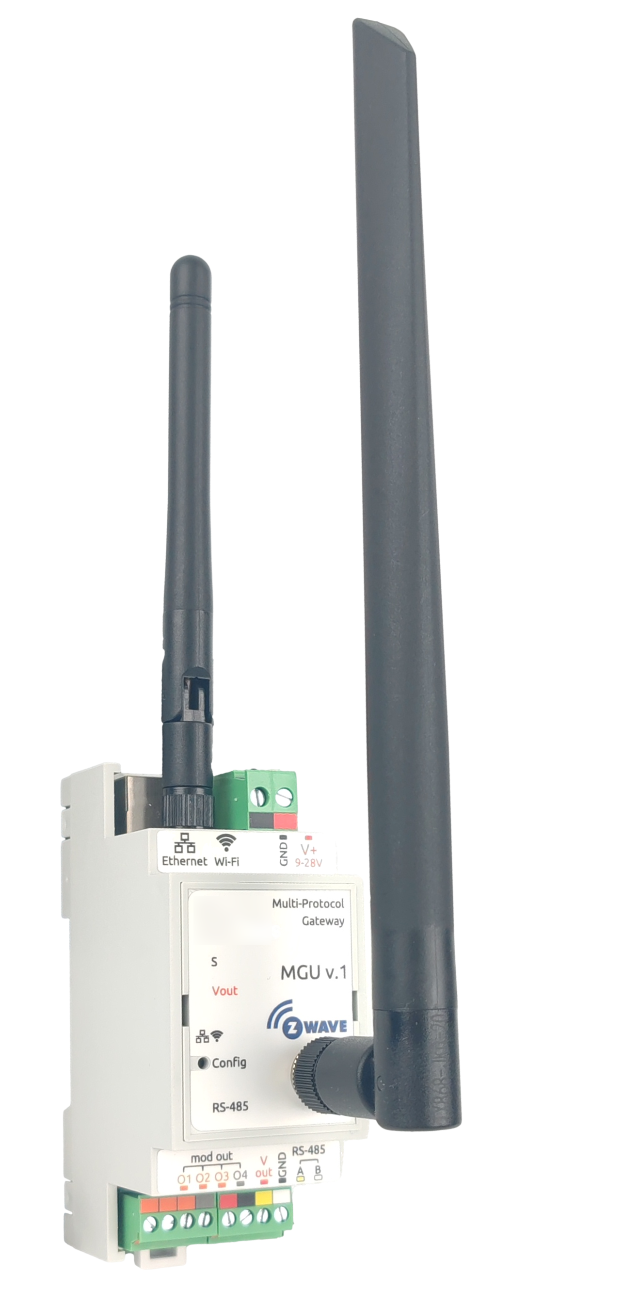
With the WBE2R-R-ZWAVE-TR expansion module installed, WB-MGU supports Z-Wave and Z-Wave Long Range. The module uses the Trident IoT T32CZ20 radio chip. Select the WB-MGU variant with 8 MB PSRAM to run the Z-Way Controller SDK on its ESP32.
The Z-Way Controller SDK provides HTTP and WebSockets APIs, together with an MQTT client for integration with external systems. An optional Matter Bridge exposes supported Z-Wave devices to a Matter ecosystem.
| Parameter | Value |
| Expansion module | WBE2R-R-ZWAVE-TR |
| Radio chip | Trident IoT T32CZ20 |
| Antenna connector | RP-SMA |
| Protocols | Z-Wave; Z-Wave Long Range |
| Roles | Z-Wave controller; Z-Wave end device |
| Controller software | Z-Way Controller SDK |
| PSRAM for the SDK | 8 MB |
| Available APIs and integration | HTTP; WebSockets; MQTT client |
| Optional integration | Matter Bridge |
Zigbee support
WB-MGU supports Zigbee through the WBE2R-R-ZIGBEE-ZME expansion module, based on the Silicon Labs EFR32MG21 radio chip and equipped with an RP-SMA antenna connector. The Z-Way Controller SDK provides the Zigbee controller functionality on the ESP32. Select the WB-MGU variant with 8 MB PSRAM to run the Z-Way Controller SDK.
HTTP and WebSockets APIs, together with an MQTT client, are available for integration with external systems. An optional Matter Bridge exposes supported Zigbee devices to a Matter ecosystem.
| Parameter | Value |
| Expansion module | WBE2R-R-ZIGBEE-ZME |
| Radio chip | Silicon Labs EFR32MG21 |
| Antenna connector | RP-SMA |
| Protocol | Zigbee |
| Role | Zigbee coordinator / controller |
| Controller software | Z-Way Controller SDK |
| PSRAM for the SDK | 8 MB |
| Available APIs and integration | HTTP; WebSockets; MQTT client |
| Optional integration | Matter Bridge |
Matter (over IP)
WB-MGU can operate as a Matter controller over its Ethernet or Wi-Fi connection using the Z-Way Controller SDK. No additional RF chip or radio expansion module is required for Matter communication over IP.
To communicate with Matter over Thread devices, a Thread Border Router (TBR) is required to connect the Thread network to the IP network.
By default, only on-network commissioning is supported. Devices must first be commissioned using an existing Matter controller, such as Apple Home, Google Home or another compatible controller. They can then be shared with WB-MGU through Matter multi-admin commissioning.
For full commissioning over Bluetooth Low Energy (BLE), install the WBE2R-R-ZIGBEE-ZME expansion module with BLE firmware.
HTTP and WebSockets APIs, together with an MQTT client, are available for integration with external systems.
| Parameter | Value |
| Protocol | Matter over IP |
| Network connection | Ethernet or Wi-Fi |
| Role | Matter controller |
| Additional RF chip | Not required for Matter communication over IP |
| Matter over Thread | Requires a Thread Border Router (TBR) |
| Default commissioning | On-network only; commission with an existing Matter controller first, then share with WB-MGU |
| Full BLE commissioning | WBE2R-R-ZIGBEE-ZME expansion module with BLE firmware |
| Controller software | Z-Way Controller SDK |
| Available APIs and integration | HTTP; WebSockets; MQTT client |
Device flashing
Flashing connector and debug console
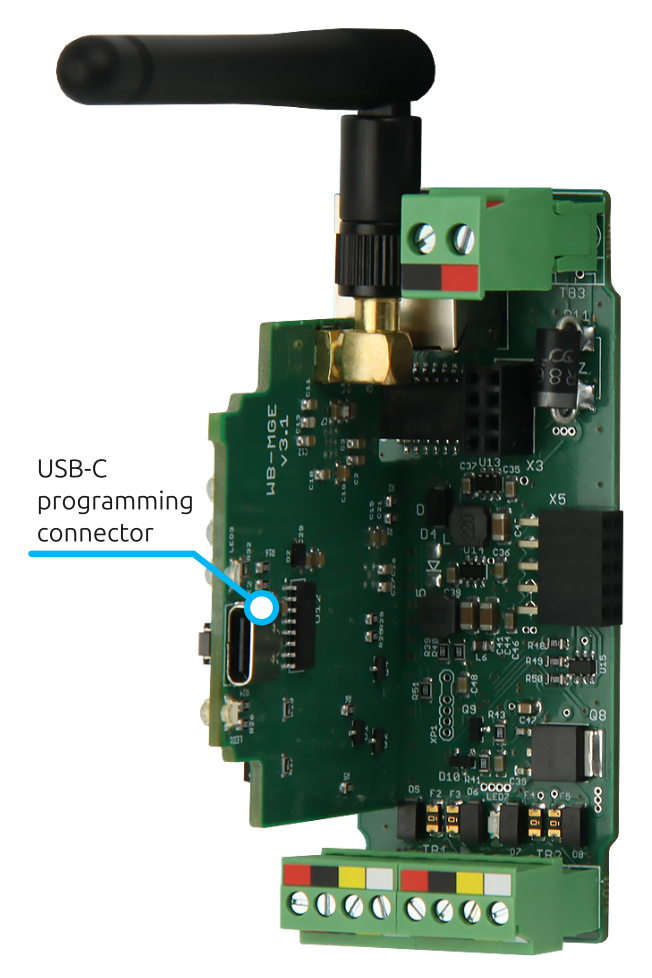
The module is based on the ESP32 chip, and a USB-C programming connector is installed on the board.
To access the USB-C connector, remove the top cover of the device by prying it from the side with something thin. You can also get debug output from the module through this connector. When connected to a computer via USB, the module is detected as an ACM device that can be opened in any terminal program.
Important: when using the debug console, first connect the USB-C cable to the computer and the WB-MGU, and only then power up the gateway. This helps avoid a device reboot, see ERRWB-MGEv30001 for details.
Writing firmware
For flashing, you can use the esptool utility or an analog. A USB-UART converter based on CH343 is built into the device.
You can check the connection by requesting the chip ID, for example:
$ esptool.py -p /dev/ttyACM0 -b 115200 chip_id
esptool.py v4.8.1
Serial port /dev/ttyACM0
Connecting......
Detecting chip type... Unsupported detection protocol, switching and trying again...
Connecting.....
Detecting chip type... ESP32
Chip is ESP32-U4WDH (revision v3.1)
Features: WiFi, BT, Dual Core, 240MHz, Embedded Flash, VRef calibration in efuse, Coding Scheme None
Crystal is 40MHz
MAC: 2c:bc:bb:31:8b:00
Uploading stub...
Running stub...
Stub running...
Warning: ESP32 has no Chip ID. Reading MAC instead.
MAC: 2c:bc:bb:31:8b:00
Hard resetting via RTS pin...
GPIO and interfaces
Below are tables with the connection of interface modules and the addresses of the expander outputs.
| ESP32 | GPIO18 | GPIO23 | GPIO0 | GPIO5 | GPIO19 | GPIO22 | GPIO21 | GPIO25 | GPIO26 | GPIO27 |
|---|---|---|---|---|---|---|---|---|---|---|
| RTL8201FI | MDIO | MDC | CLK | RST | TXD0 | TXD1 | TXEN | RXD0 | RXD1 | CRS_DV |
| TCA9535 | SDA | SCL | PD00 | PD02 | PD04 | PD05 | PD06 | PD07 |
|---|---|---|---|---|---|---|---|---|
| ESP32 | GPIO32 | GPIO33 | ||||||
| RS485 | terminator ON | bias ON | ||||||
| VOut and LED VOut | ON | |||||||
| LED Wi-Fi | OFF | |||||||
| LED Eth | OFF | |||||||
| Status | ON |
In the table above, ON means that a logic one on the port turns the corresponding node on. For the Status LED, the LED is on when the port is in the HiZ state. TCA9535 has the standard bus address 0x20.
| PSRAM64H | CE | CLK | SIO0 | SIO1 | SIO2 | SIO3 |
|---|---|---|---|---|---|---|
| ESP32 | GPIO9 | GPIO6 | GPIO8 | GPIO17 | GPIO7 | GPIO11 |
| ESP32 | GPIO14 | GPIO12 | GPIO15 |
|---|---|---|---|
| RS485 | TX | RX | RTS |
| ESP32 | GPIO10 | GPIO4 | GPIO13 |
|---|---|---|---|
| WBE2 | TX | RX | RTS |
In both cases, RX is an input and TX is an output for the ESP32.
| ESP32 | GPIO34 |
|---|---|
| Config (B1) | + |
In this case, the button pulls the ESP32 pin to logic zero when pressed.
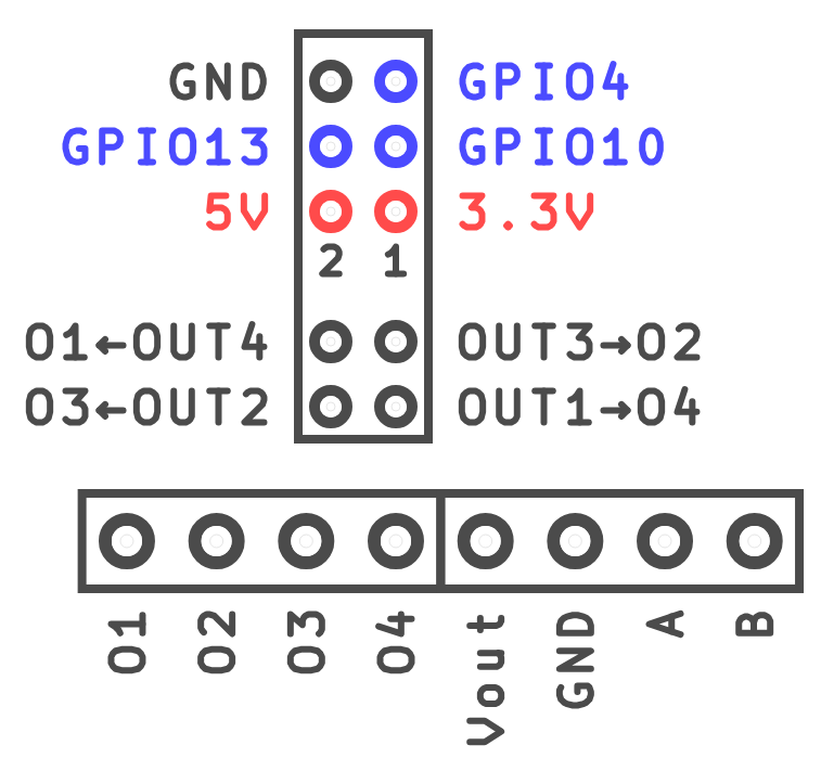
Inside the housing, the board has a connector for a WBE2 extension module — a 2×6 double-row socket with a 2.54 mm pitch. The row between the OUT pins and the power pins is not connected. Pins OUT1–OUT4 are routed to the front-panel terminals O1–O4 in reverse order: OUT1 goes to O4, OUT4 goes to O1. The GPIO lines are connected directly to the ESP32, signal levels are 3.3 V.
Images and drawings
Corel Draw 2018 (font — Ubuntu): WB-Library.cdr.zip
Visio:
- Wiren Board devices: WB-Visio-Lib.zip.
- Panels, circuit breakers, contactors, and more by a third-party developer.
SVG: WB-Library.svg.zip

Module dimensional drawing (DXF): WB-MGEv3.dxf.zip
Module dimensional drawing (PDF): WB-MGEv3.pdf
Symbol library for AutoCAD Electrical: Wirenboard-AE-base.zip
-
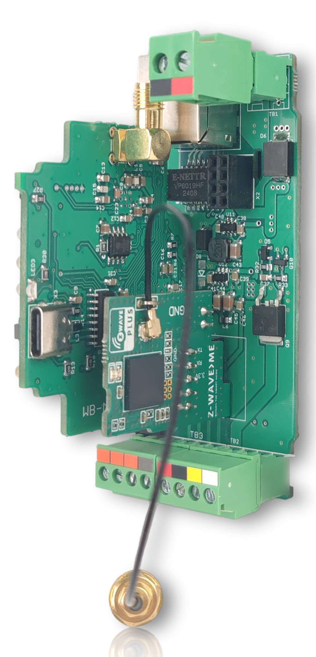 WB-MGU board with a Z-Wave module installed
-
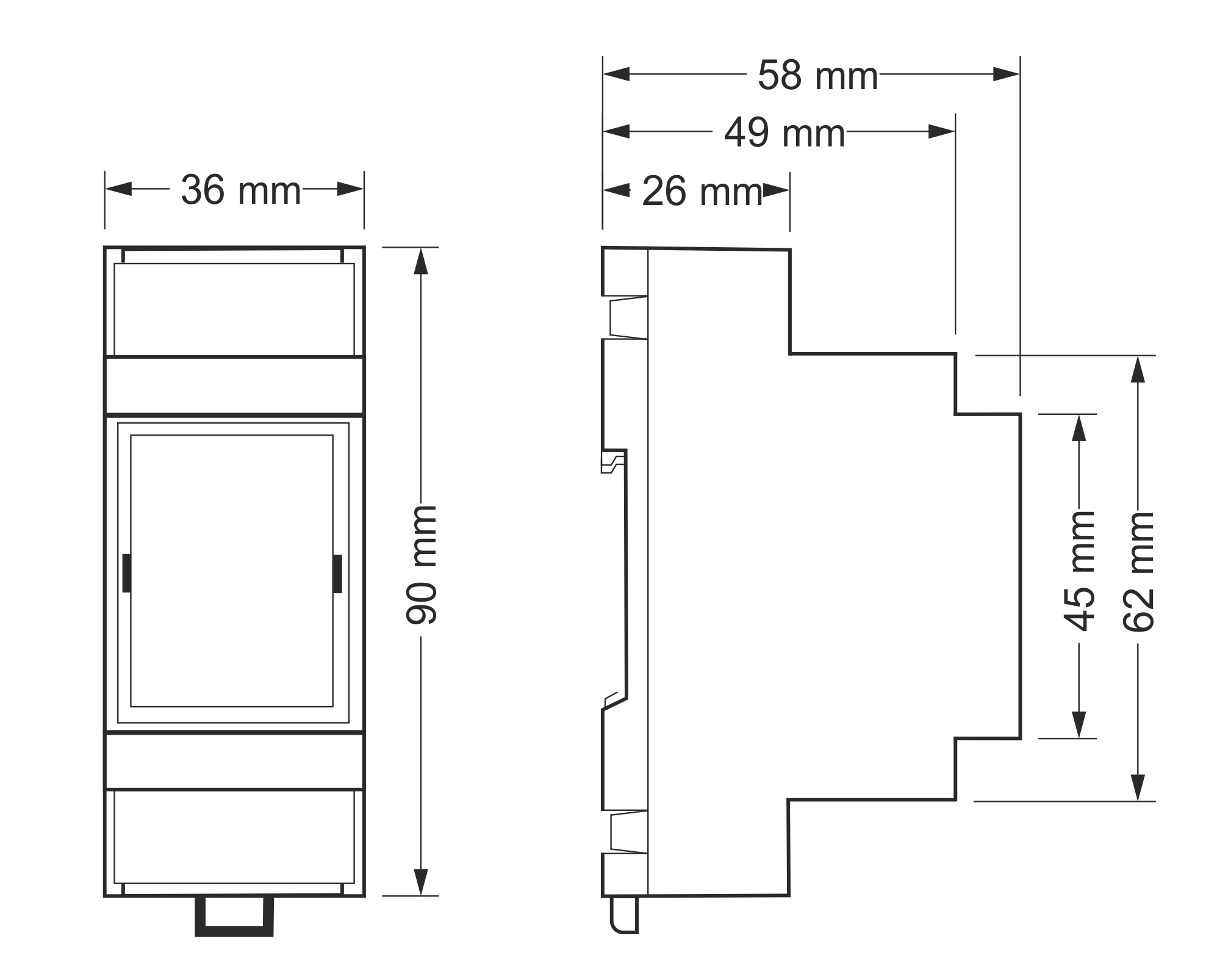 Overall dimensions