 Documentation
WB-UPS v.3
DIN-rail uninterruptible DC power supply
Covered order codes (1)
WB-UPS— WB-UPS v.3; manufacturer model, SmartSD order code not verified
This page describes the newer WB-UPS v.3; for the previous version, see WB-UPS v.2.
This page describes the latest hardware revision with the latest stable firmware. If your device runs older firmware, update it where possible (see Firmware update).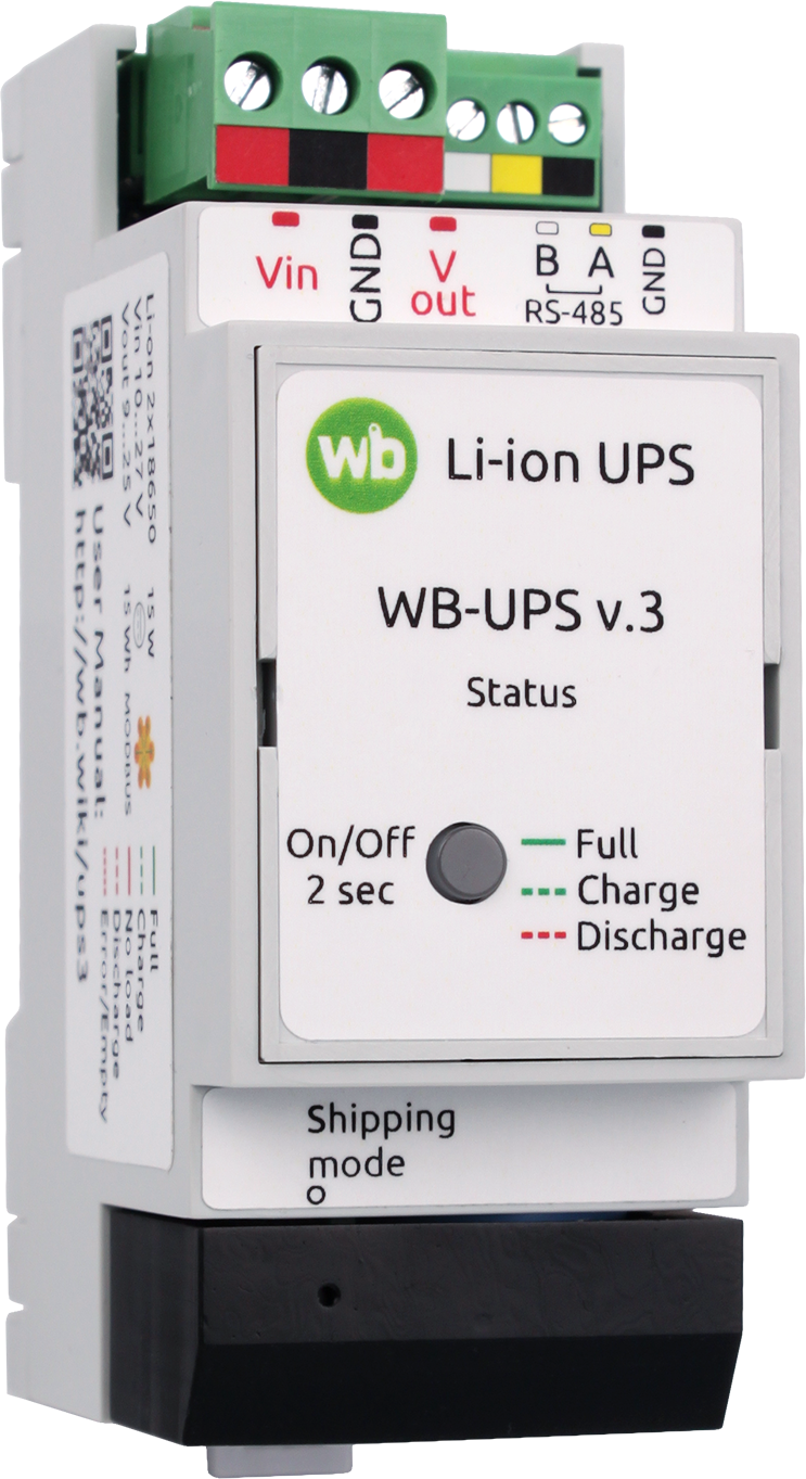
Purpose
WB-UPS v.3 is a lithium-ion uninterruptible power module that keeps a controller, connected modules and other loads running when external power fails.
Differences from the previous version
| WB-UPS v.2 | WB-UPS v.3 | |
|---|---|---|
| Main specifications | ||
| Input voltage | 12–28 V | 10–27 V |
| Output voltage
(on battery) |
11.2 V / 22.3 V | 9–25 V, configurable |
| Output voltage setting | Manual switch | Automatic / manual via Modbus |
| Rated / peak power | 15 / 20 W | 15 / 20 W |
| Battery energy | 10 Wh | 15 Wh |
| Power consumption while charging | 6 W | 6 W at 600 mA charging current |
| Cells | ||
| Type | Lithium-ion polymer | Li-ion 18650 |
| Nominal voltage | 3.7 V | 3.6 V |
| Rated capacity | 2 × 1800 mAh | 2 × 2600 mAh |
| Connection and operation | ||
| Power and load connection | Vin - GND - GND - Vout | Vin - GND - Vout |
| Modbus interface | No | Yes |
| Status output | Yes | No
available through a Modbus register |
| Battery voltage output | Yes | No
available through a Modbus register |
| Module size | 2 DIN modules
36 × 90 × 58 mm |
2 DIN modules
36 × 90 × 58 mm |
| Ambient temperature | −20 to +45 °C | −20 to +45 °C |
Technical specifications
| Specifications | |
|---|---|
| Input voltage | 10–27 V |
| Output voltage on battery | 9–25 V |
| Rated power | 15 W |
| Peak power | 20 W |
| Nominal energy | 15 Wh |
| Runtime at 15 W | 60 minutes |
| Power consumption while charging | up to 6 W at 600 mA charging current |
| Self-consumption from Vin with the battery fully charged | up to 18 mA |
| Battery current when switched off | up to 210 µA |
| Battery current in shipping mode | 70 µA |
| Cell specifications | |
| Type | 18650 Li-ion |
| Nominal voltage | 3.6 V |
| Cells per battery | 2 |
| Operating conditions | |
| Ambient air temperature* | −20 to +45 °C |
| Relative humidity | Up to 95%, non-condensing |
| Recommended storage temperature | −5 to +35 °C |
| Terminal blocks and wire cross-sections | |
| Recommended wire cross-section with insulated wire-end ferrules | control inputs: 0.35–1 mm2 — single ferrule; 0.35–0.5 mm2 — twin ferrule,
power inputs: up to 2.5 mm2 — single ferrule; up to 1.5 mm2 — twin ferrule |
| Standard ferrule sleeve length | 8 mm |
| Screw tightening torque | control inputs: 0.2 N·m,
power outputs: 0.5 N·m |
| Warranty | 2 years |
| Service life | 5 years |
| Dimensions | |
| Width, DIN modules | 2 |
| Overall dimensions (L × W × H) | 36 × 90 × 58 mm |
| Weight (including box) | 185 g |
*Charging is permitted at battery temperatures of +5 to +50 °C; battery discharge operation at −20 to +60 °C.
Operating principle
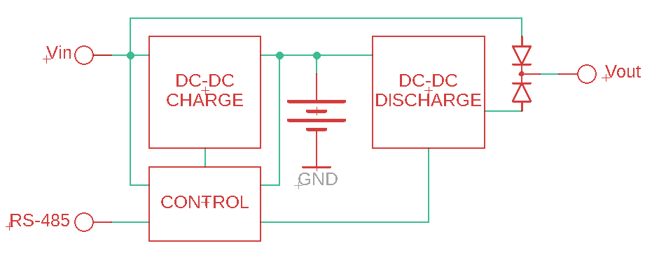
WB-UPS v.3 contains two Li-ion cells, a charging circuit and a boost converter. A microcontroller controls the converters.
A fuse and a supervisor IC protect the battery against overcharge, overdischarge and overcurrent. Hardware protection prevents charging below freezing and protects against overheating. A balancing circuit equalizes cell voltages.
Measured and calculated parameters:
- Input voltage* at Vin;
- Output voltage* at Vout;
- Battery voltage;
- Battery current: positive during charging, negative during discharge;
- Charging input current: current drawn from Vin to charge the battery;
- Load current while powered by the battery;
- Battery state of charge, smoothed and raw;
- Battery temperature.
*Maximum measurable voltage is 25.6 V; higher actual voltages are displayed as 25.6 V.
Current passing from Vin to Vout through the ideal diode is not measured. Load power can be measured only during battery operation.
Use Modbus RTU over RS-485 to read measurements and calculated values and change settings and operating modes.
Operation with external input power
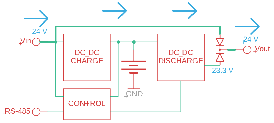
With power at Vin, the ideal diode conducts to Vout. The discharge boost converter remains operating, ensuring uninterrupted load power when input voltage disappears.
If input voltage exceeds the configured converter output by more than 0.6 V, battery consumption is negligible and the external supply powers the load.
WB-UPS v.3 is always on while external input power is present.
Converter output voltage is set automatically or manually.
Automatic mode:
- converter output is set 0.7 V below Vin, within 10–24.9 V;
- the converter setting changes 10 seconds after input voltage changes. If Vin falls, the battery powers the load for those first 10 seconds;
- below 10 V input, the output setting remains unchanged;
- at 25.6 V input or above, output is set to 24.9 V, because WB-UPS v.3 cannot measure above 25.6 V.
Manual mode:
- the boost converter produces the configured voltage independently of Vin;
- if input voltage exceeds that setting, it passes directly through the diode to the output, bypassing the converter. Output voltage therefore cannot be lower than input voltage;
- if input voltage falls below the setting:
- the battery powers the load and discharges;
- battery charging stops;
- after the battery is discharged, the boost converter shuts down and output voltage equals input voltage.
- select an output setting at least 0.7 V below the external supply voltage;
- output voltage may decrease during battery operation if parallel operation is enabled, as it is by default. For a single UPS, disable parallel operation for more accurate output voltage;
- for safety, a new converter voltage setting is applied only when input voltage is 0.7 V above it. Until then, the previous setting remains, or 11.5 V immediately after power-on;
- the voltage selection mode and manual setpoint are configurable; see Configuration, Register map).
Battery charging
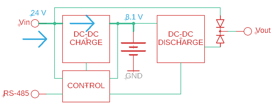
Charging occurs only when all conditions are met:
- input voltage is present;
- no current is drawn from the battery: input voltage exceeds the configured output voltage;
- battery temperature is +5 to +50 °C;
- battery voltage is below 8.1 V.
Two series Li-ion cells reach full charge at 8.4 V, but the module charges only to 8.1 V. Using less than full capacity extends battery life.
Default charging current is 600 mA and can be changed in the settings.
A full charge takes up to 4.5 hours.
Self-discharge and recharge
Unlike lead-acid batteries, Li-ion cells must not be continuously trickle-charged. When WB-UPS battery voltage reaches 8.1 V and charging current falls below 100 mA, charging stops.
Even with input power present, internal circuits slowly discharge the battery at approximately 250 µA. Voltage and state of charge therefore gradually decrease, about 2% per week. Below 7.8 V, charging restarts, fully charges the battery, then stops again. Over several months, the state-of-charge graph may cycle between roughly 85% and 100%.
This is normal. Self-discharge cannot be eliminated, and the recharge threshold reduces the frequency of charge cycles to extend battery life.
Battery operation
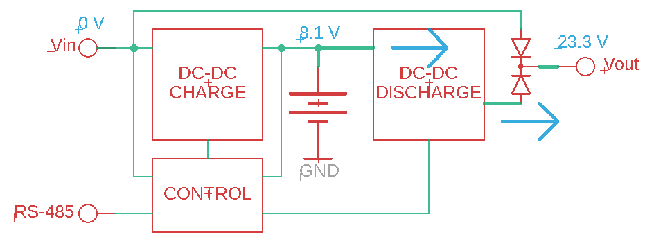
When input power disappears, the device switches to battery operation. Output voltage is:
- in automatic mode, 0.7 V below the input voltage recorded 10 seconds before power loss;
- in manual mode, the configured value.
If parallel operation is enabled, as it is by default, output voltage may decrease. For a single UPS, disable parallel operation for better output-voltage accuracy, especially with a manual setpoint.
On battery, the converter supplies 15 W continuously and up to 20 W briefly. Exceeding the battery power limit causes output voltage to fall.
Components and cells heat during battery operation in proportion to load power. Above 60 °C battery temperature, output is disabled until the battery cools.
For loads near the 15 W rating, keep ambient temperature at or below 30 °C; otherwise battery overtemperature may disconnect the load before capacity is exhausted. Reduce load power for sustained battery operation at higher ambient temperatures.
Load control during battery operation
Use Load control in backup power mode to disconnect/reconnect the load while on battery. Periodic operation, for example only during measurements, can extend system runtime.
With input voltage present, this register has no effect: power passes from Vin to Vout through the diode.
If the controller is powered by the same WB-UPS v.3, disconnecting the load also turns the controller off.
Shipping mode
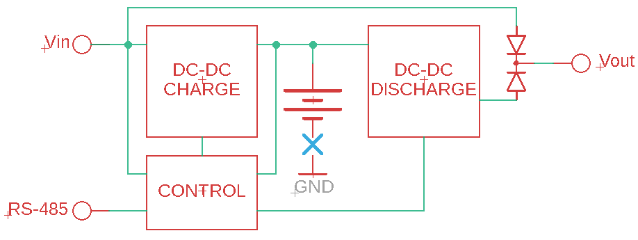
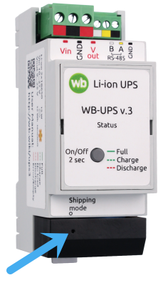
After factory testing, WB-UPS v.3 is placed in shipping mode:
- the battery is disconnected from consumers;
- long storage is possible with minimal drain, approximately 70 µA;
- the front button cannot switch the device on.
Apply power to Vin to leave shipping mode and enter normal operation.
Enable shipping mode using the recessed button through the side-cover opening beside Shipping mode, only with no power at Vin. This is recommended for long unpowered storage, for example in an assembled panel awaiting shipment.
Protection mechanisms
18650 Li-ion cells are safe when handled correctly: avoid charging/discharging an overheated battery, excessive currents including short circuits, overcharging and severe mechanical impact or cell-can damage. Avoid subzero charging and deep discharge to extend cell life.
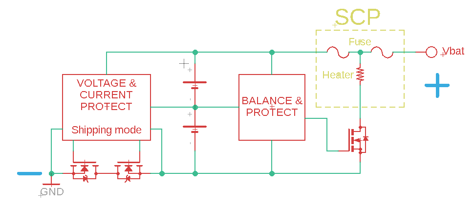
WB-UPS v.3 includes:
- a multifunction Li-ion protection circuit, VOLTAGE & CURRENT PROTECT, which disconnects the battery on overvoltage, undervoltage, excessive charging/discharging current or short circuit. It also implements shipping mode;
- a controlled fuse, SCP, which opens on excessive current like an ordinary fuse and has a Heater input. An additional independent BALANCE & PROTECT circuit can trigger that input to permanently open the fuse if either cell voltage exceeds its limit;
- a cell-balancing circuit, BALANCE & PROTECT, which equalizes charge and prevents overcharging one cell while the other remains discharged;
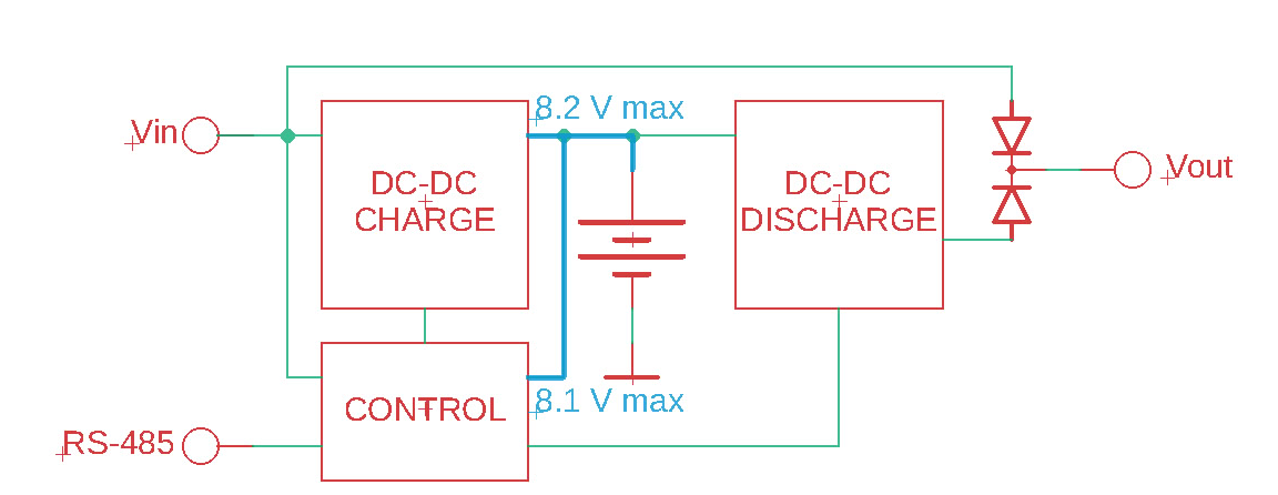
- dual charge-voltage control: software through the microcontroller and hardware through a dedicated IC;
- hardware charging/discharging current limits;
- dual software/hardware temperature monitoring, preventing discharge above +60 °C or below −20 °C and charging above +50 °C or below +5 °C.
Control button and indication
The front-cover button switches the module on/off and indicates its state. The button can switch the module off only when external power is absent. With voltage at Vin, the module is always on.
Button illumination indicates:
| Indicators | Condition | |
| Steady green (Full) | 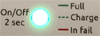
|
|
| Slow green flashing, 0.5 Hz (Charge) | 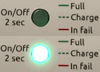
|
|
| Steady red (In fail) | 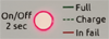
|
|
| Slow red flashing, 0.5 Hz (In fail) | 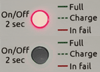
|
|
| Fast red flashing, 4 Hz | 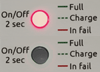
|
|
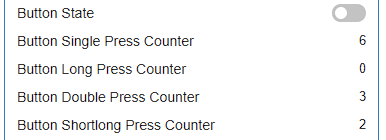
The Modbus registers expose button state and counters for four standard press types: short, long, double-short and short-then-long, allowing the button to serve as an additional control.
Without external power, a long press switches the device off. Other press types are unrestricted.
Connecting multiple WB-UPS v.3 modules in parallel
For a high-power load, preferably divide it into groups of no more than 15 W and use a separate WB-UPS v.3 for each. If that is impossible, for example a single load exceeds 15 W or changes over time, or longer runtime is needed, several WB-UPS v.3 units can operate in parallel.
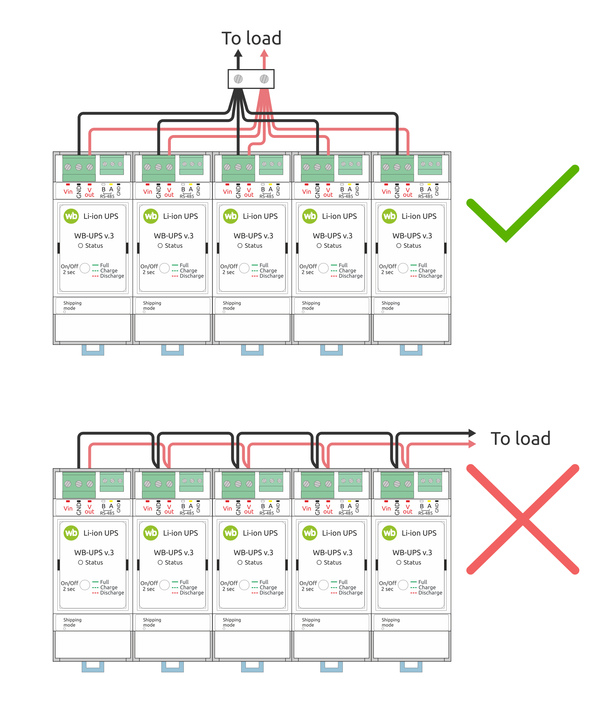
Paralleling outputs combines their power capability and battery energy.
Parallel operation is enabled by default. Units share the load autonomously: as power demand rises, each reduces its output setpoint to transfer part of the load to neighbouring units.
Output voltage may decrease by up to 10% at maximum load.
The source example uses three parallel WB-UPS v.3 units for a nominal 35–40 W load, with 45 Wh total battery energy, and states that a 15 W load can run for more than three hours.
Perfectly equal sharing is impossible due to wire resistance and voltage-setting tolerances. For the best use of battery capacity:
- select manual voltage mode and the same output voltage on every parallel unit;
- use star wiring: a separate lead from each UPS to the load or to a common terminal block feeding the loads;
- use equal conductor cross-sections and lengths to minimize resistance differences;
- allow 2–3 W power margin per WB-UPS v.3.
Without margin, for example a 45 W load on three units, one UPS may exceed its rating and heat more, causing premature thermal shutdown.
Installation
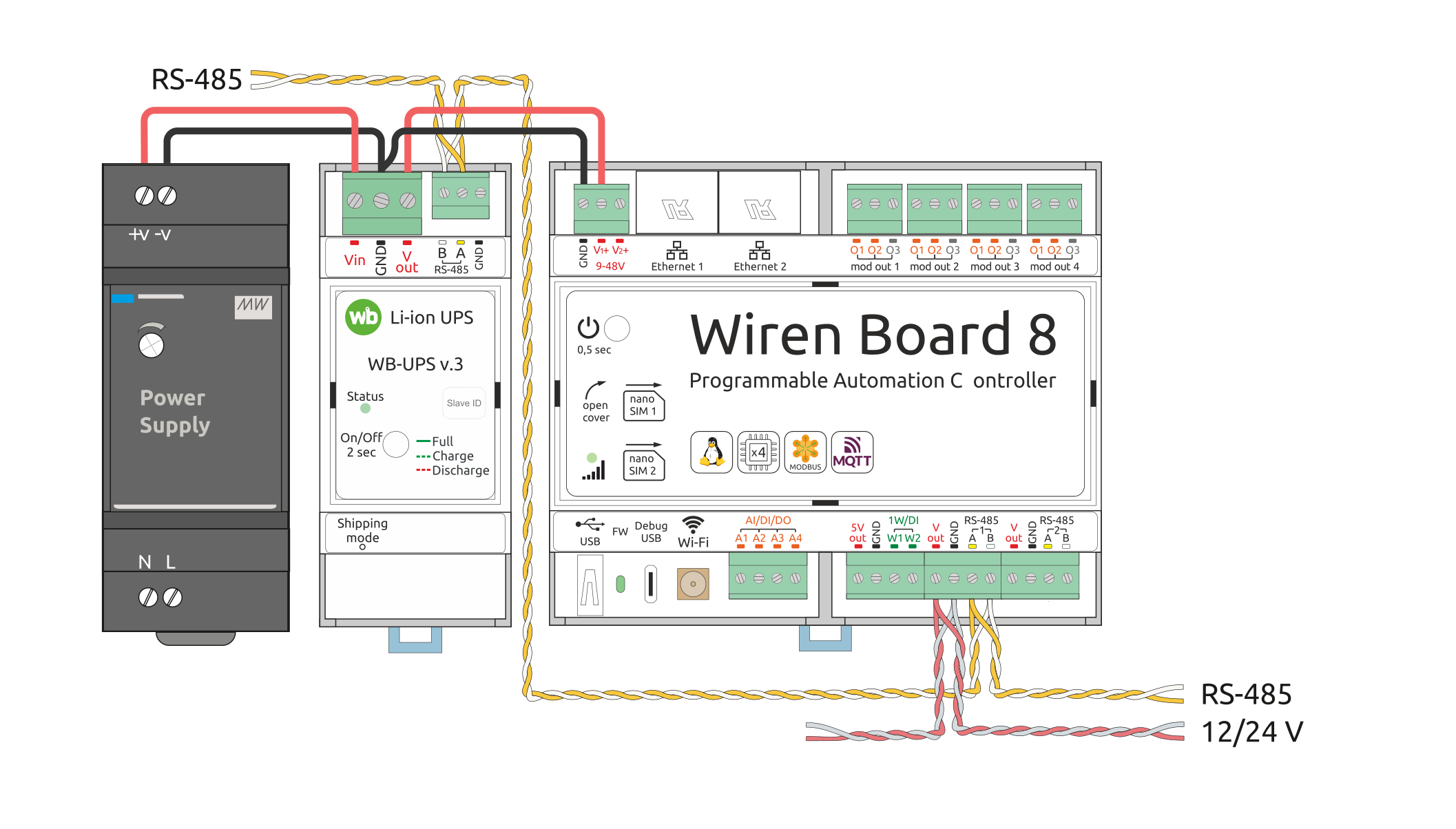
Mount the device on a standard 35 mm DIN rail.
Avoid overheating: do not install beside hot components such as contactors. Leave approximately 1 cm between neighbouring devices for cooling, for example using a DIN-rail end stop.
The diagram shows a load supplied through WB-UPS. Connect the main supply to Vin and GND and the backed-up load to Vout and GND.
Wiren Board controller web interface
Selecting a template
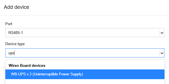
To display the device on the Devices tab of the Wiren Board controller web interface, add it automatically by scanning for Wiren Board devices on RS-485 or manually by selecting the template WB-UPS v.3.
If the template is missing or the device view differs from this example, update device firmware and controller software.
Controlling the device and viewing values
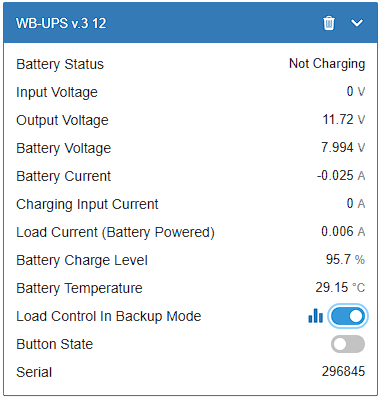
The web interface allows you to control device outputs and view readings. To change the displayed channels, edit the device configuration in the wb-mqtt-serial driver settings.
Available controls depend on the selected mode.
Configuration
Configuration methods
- Set the parameters in the Wiren Board controller web interface under Settings → Configs → Serial devices driver configuration. If these items are unavailable, check your access level.
- Write settings to the Modbus registers of the module from the controller console using the utility modbus-utils-rpc or modbus_client.
- Without a Wiren Board controller, use the Wiren Board device web configurator or other software; see Using Wiren Board Modbus devices without a controller. You will need a computer with an interface converter: USB-RS485.
Our devices are continually improved. If settings described in this manual are missing, update the device firmware and controller software.
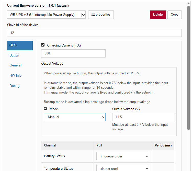
Modbus operation
Wiren Board devices use Modbus RTU. The physical connection uses the RS-485.
interface. All main commands for reading and writing one or multiple registers are supported. See the list in the Modbus protocol description.
The module can be configured:
- in the Wiren Board controller web interface;
- using the Wiren Board device web configurator;
- using third-party software.
Default port settings
| Value default |
Parameter name in the web interface |
Parameter |
|---|---|---|
| 9600 | Baud rate | Baud rate, bit/s |
| 8 | Data bits | Number of data bits |
| None | Parity | Parity |
| 2 | Stop bits | Number of stop bits |
In current firmware, setting Stop bits is optional: the device also operates correctly when its number of stop bits differs from the Modbus master setting.
For a faster response, we recommend increasing the baud rate to 115200 bit/s; see Communication parameter settings
Modbus address
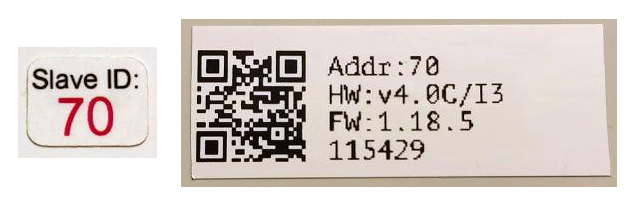
Each device on the bus must have a unique address from 1 to 247. The factory-assigned address is printed on labels on the enclosure (top cover, side or underside). Devices in a production batch are assigned different addresses, so devices in one order will usually have different addresses.
For instructions on finding, changing or resetting the address, see Wiren Board device Modbus address.
Fast Modbus extension
Fast Modbus extends standard Modbus with rapid discovery of Wiren Board devices on RS-485 and event polling.
These features are enabled by a special command from the master, so Wiren Board devices remain compatible with third-party equipment.
Not every register supports event generation. Check the register map: event-capable registers are marked with ⚡. See Fast Modbus.
Register map
Firmware updates and resetting settings
Wiren Board devices support firmware updates over Modbus. This allows bugs to be fixed at the installation site and, where technically possible, new features to be added. Settings stored in the device are retained during a firmware update.
Instructions:
- Firmware update ()
- Resetting settings
- Connection parameter settings
- Modbus address: find, reset or change
- Updating the bootloader
New firmware releases are listed in the firmware changelog.
Known issues
WB-UPS v.3 hardware issues and characteristics identified during operation.
Hardware revisions
Device images and drawings
-
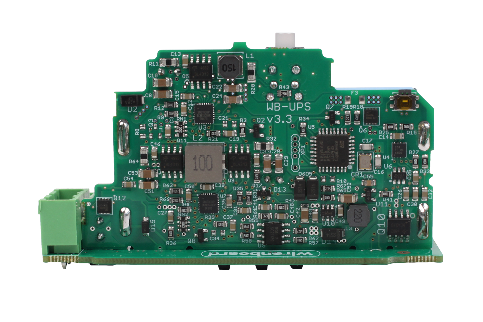 WB-UPS v.3 PCB
-
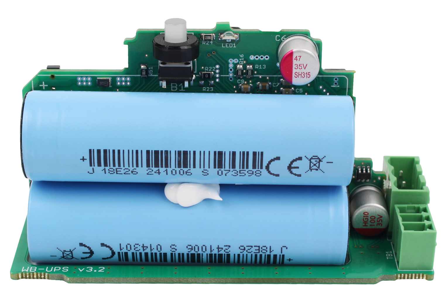 Battery pack
-
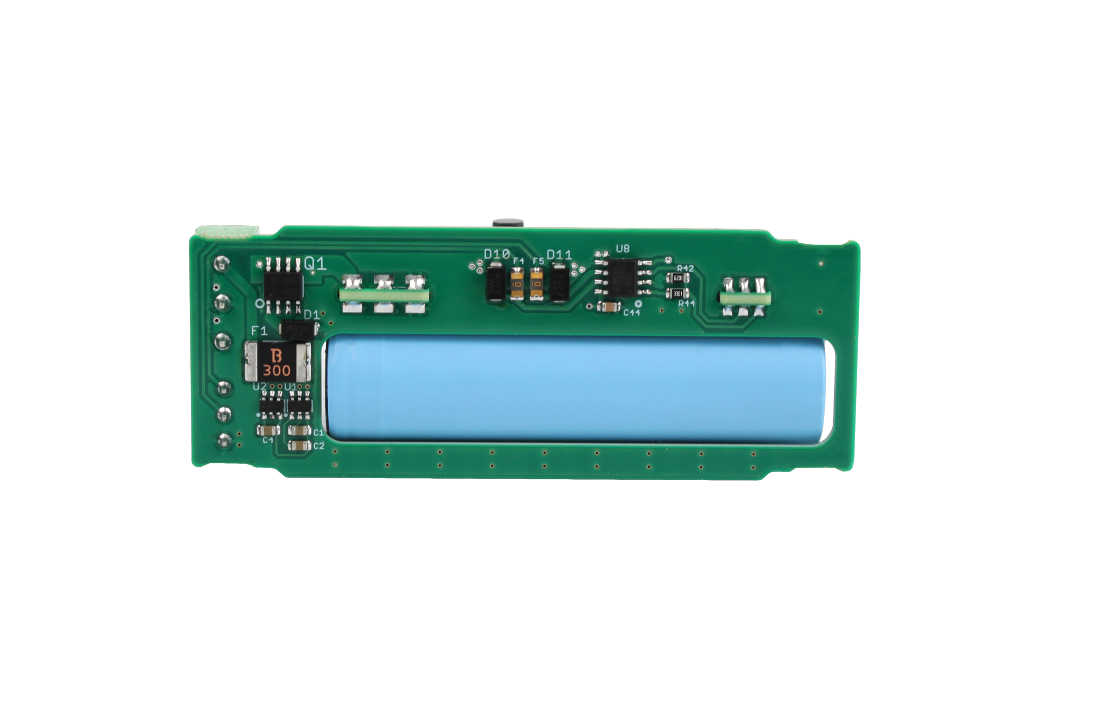 WB-UPS v.3 lower PCB
-
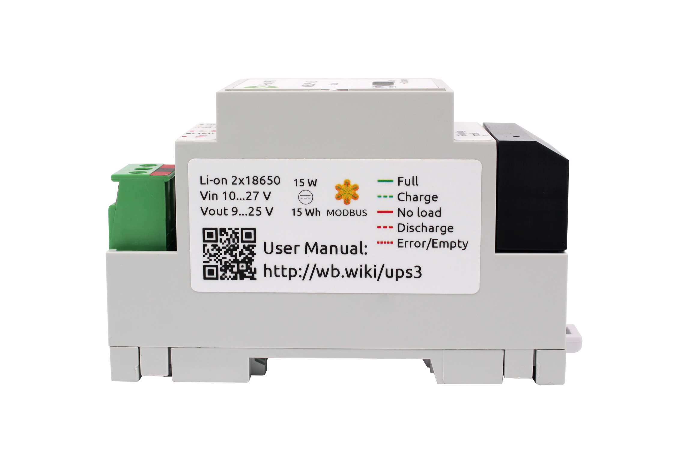 WB-UPS v.3 side view
-
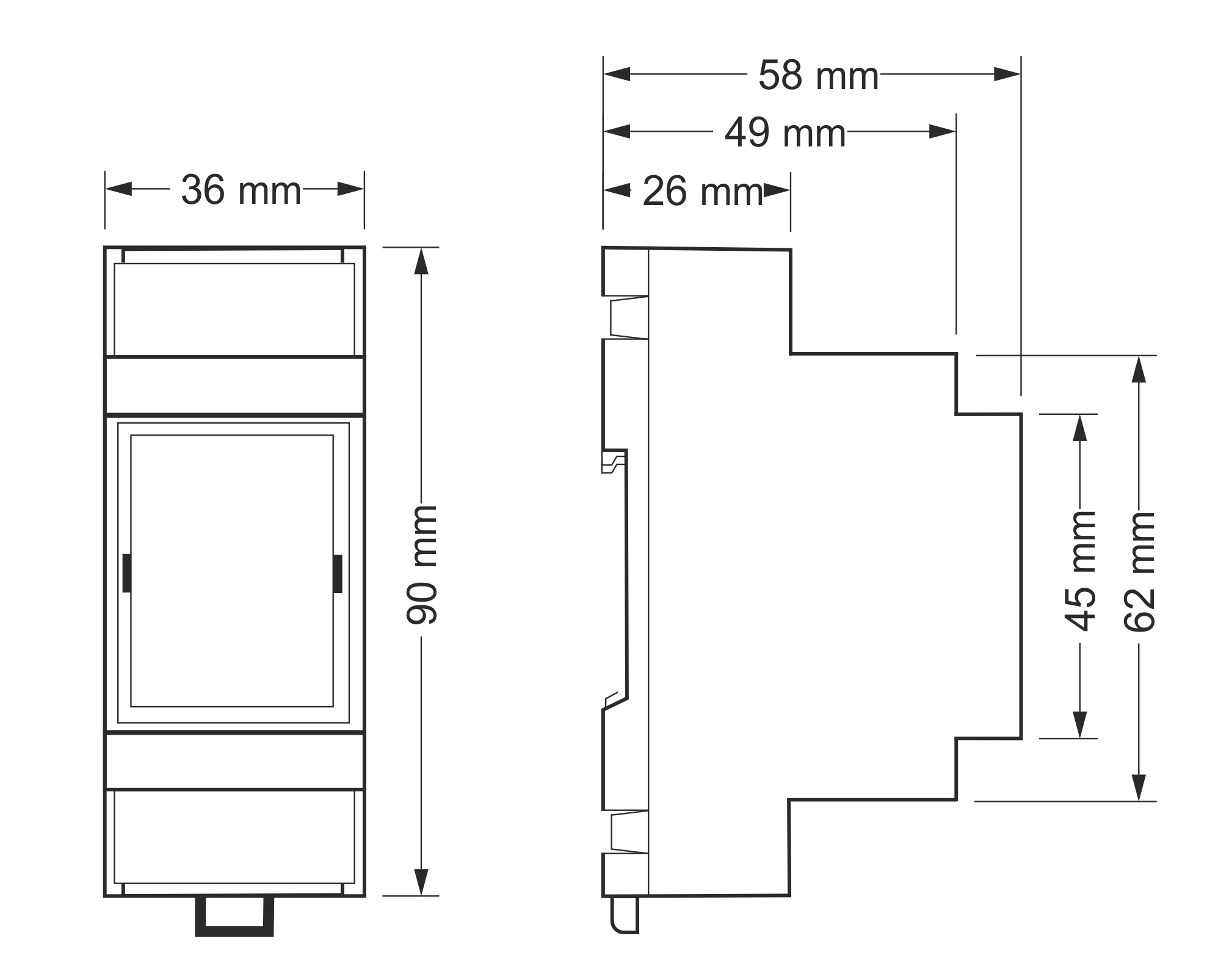 Overall dimensions
CorelDRAW 2018 (font: Ubuntu): File: WB-Library.cdr.zip
Visio:
- Wiren Board devices: File: WB-Visio-Lib.zip.
- Enclosures, circuit breakers, contactors and other third-party symbols.

Module dimensional drawing (DXF): File: WB-UPSv3.dxf.zip
Module dimensional drawing (PDF): File: WB-UPSv3.pdf
AutoCAD Electrical schematic symbol library: File: Wirenboard-AE-base.zip