 Documentation
WBMZ6-BATTERY
Li-ion battery backup power module for Wiren Board 8.5 and later
Covered order codes (1)
WBMZ6-BATTERY— Internal Li-ion battery backup power module for Wiren Board 8.5 and later
Purpose
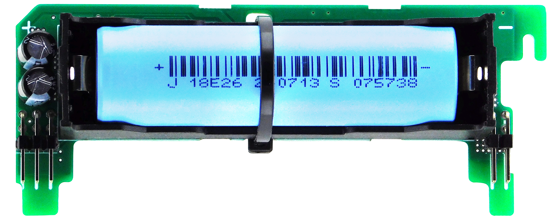
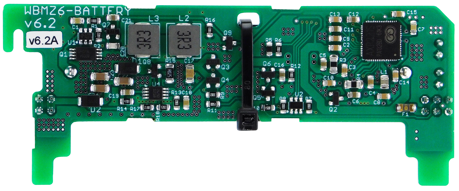
The battery module for Wiren Board 8.5 controllers is a backup power board installed inside the controller enclosure. It keeps the controller and supported connected modules operating when the external power supply fails. The assembly comprises a battery, a charge controller and power-management circuitry.
Compatibility
WBMZ6-BATTERY is designed for Wiren Board 8.5 and later controllers. Use the appropriate backup power module for earlier controller generations.
Control cabinet installation
The battery charges only when its temperature is within 4 °C to 60 ± 2 °C. Allow for the controller running 10–15 °C warmer than the surrounding air.
Prevent the controller from overheating. Do not install it next to or above contactors, relays or other heat-generating equipment.
Technical specifications
| Parameter | Value |
|---|---|
| Battery type | Li-ion, 3.7 V |
| Model | DLG NCM18650-260 |
| Rated capacity (C) | 2600 mAh |
| Charging power consumption | 3 W |
| Output power | 6 W |
| Full charge time | Approx. 4 hours |
| Runtime with controller and no modem | Up to 5 hours |
| Runtime at maximum load | 50 minutes |
| Operating temperature* | Charging: 0 to +45 °C
Discharging: −20 to +60 °C |
| Recommended storage temperature:
Up to 1 month Up to 3 months More than 3 months |
0 to +35 °C 0 to +25 °C |
| Weight | 70 g |
| Warranty | 2 years |
| Service life | 5 years |
* The specified range is the permissible module temperature. Because the module is installed inside the controller, its operating temperature may be 10 °C above ambient. The module automatically disables charging outside the permitted temperature range.
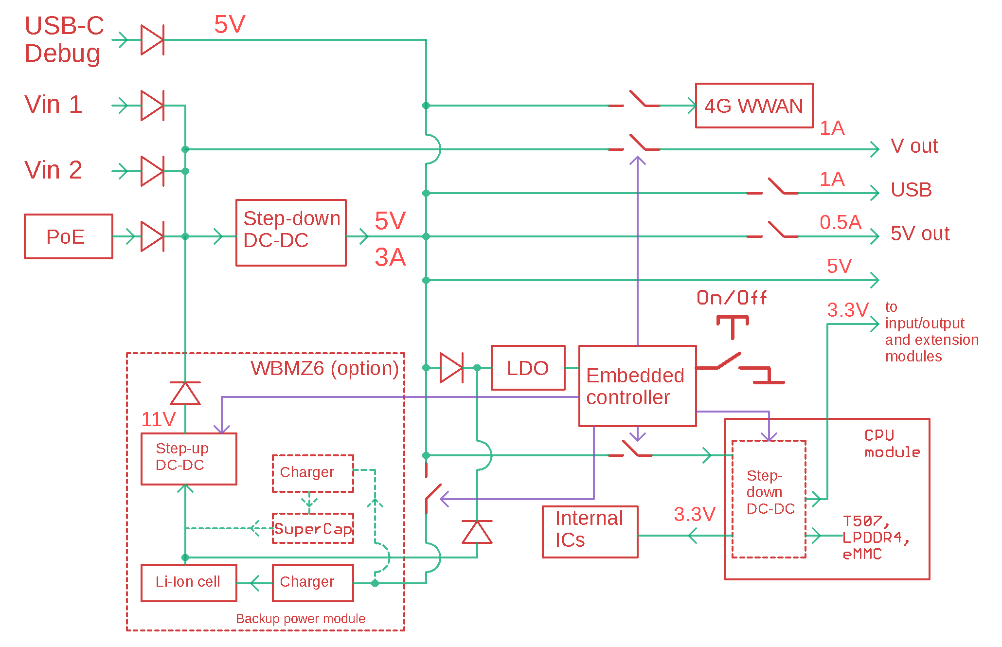
The module includes a Li-ion charging circuit with low- and high-temperature charge protection. Charging current is 600 mA and a full charge takes approximately 4 hours.
Backup power engages when the controller input voltage falls below 11 V and maintains 11 V on the internal power rail. While the controller is running from the module, 11 V is also available at the controller Vout terminal for low-power external devices drawing less than 3 W.
For correct operation, the controller supply voltage must be at least 12 V.
Maximum load power
The backup power module limits the power available to connected loads. The controller supplies USB devices, equipment connected to Vout and 5Vout, expansion modules and I/O modules.
Their combined power consumption must not exceed the limits below.
| Controller operating mode | Maximum connected-device power |
|---|---|
| With the 4G modem operating | 1.5 W |
| With the 4G modem switched off | 3.5 W |
Removal and installation
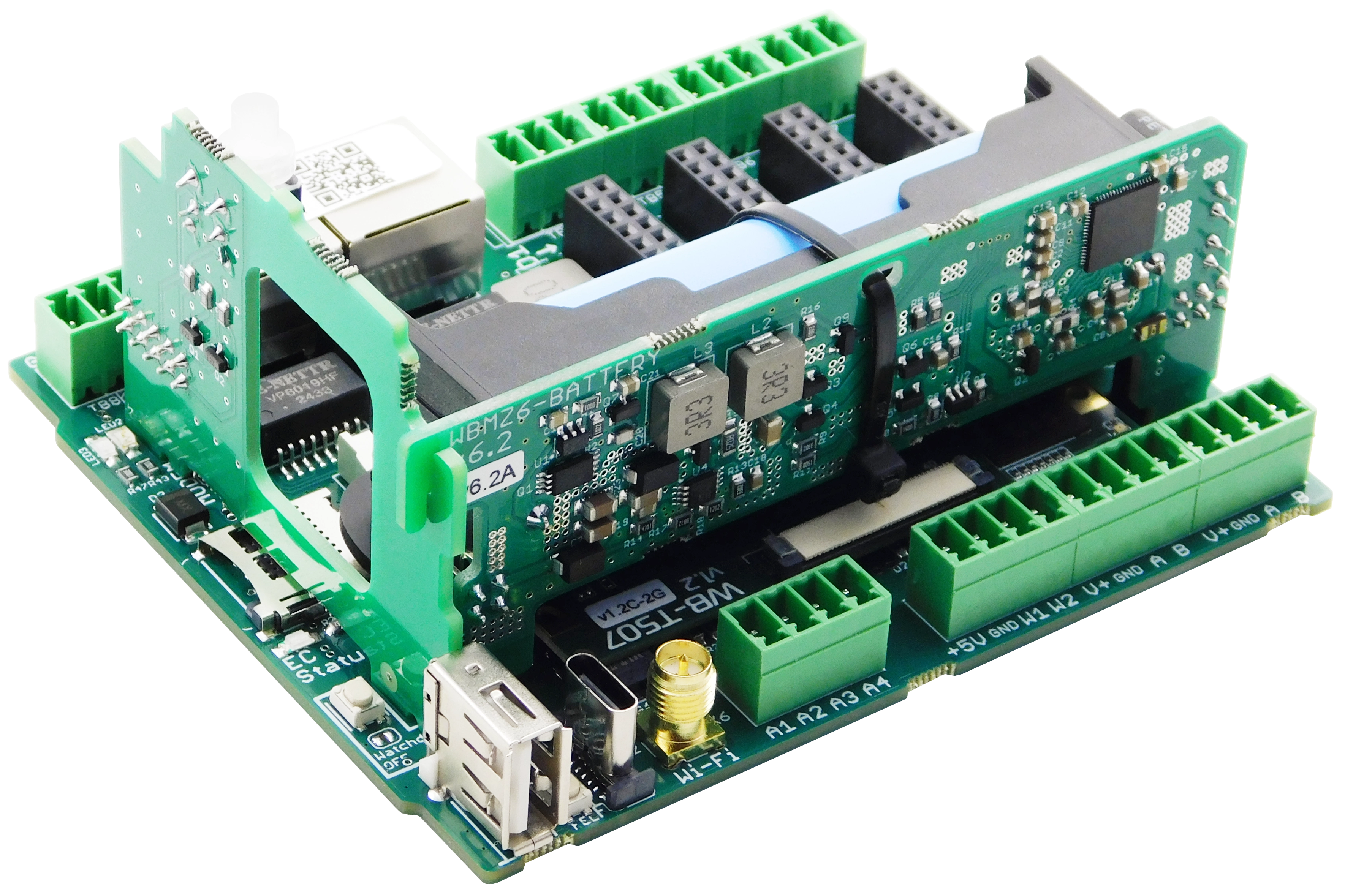
Modules ordered with a Wiren Board controller are installed at the factory. If the module was purchased separately, install it as follows:
- Disassemble the controller enclosure.
- Install the module with the correct polarity: its locating tab must enter the slot on the controller PCB.
- If a modem is installed, the corners of the backup power module PCB must interlock with the modem PCB.
- Pull the insulating film out from under the battery contact.
- Reassemble the enclosure.
Configuration
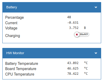
WBMZ6-BATTERY requires no configuration. Install the module, remove the insulating film from under the battery contact, then power the controller.
After installation, the Devices tab shows a Battery:
- Current — battery current in amperes. A positive value means the battery is charging; a negative value means it is discharging.
- Percentage — state of charge as a percentage of the capacity calculated during calibration.
- Voltage — battery voltage.
- Charging — indicates whether the battery is currently charging.
Battery temperature is shown by the HW Monitor, channel hwmon/Battery Temperature. Ensure that the battery temperature remains within the permitted range.
Known issues and operating notes
No known issues
Hardware revisions
The batch number is printed on a label on the side of the enclosure or on the PCB.
| Revision | Batches | Release date | Changes from the previous revision |
|---|---|---|---|
| 6.3 | v6.3A, v6.3A/1, v6.3A/2, v6.3B, v6.3B/1, v6.3B/2 - ... | 08.2026 - ... |
|
| 6.2 | v6.2D, v6.2E, v6.2F, v6.2G, v6.2H, v6.2H/1, v6.2H/2 | 07.2025 - 08.2026 |
|
| 6.2 | v6.2B, v6.2B/1, v6.2C, v6.2C/1 | 02.2025 - 07.2025 |
|
| 6.2 | v6.2A | 11.2024 |
|