 Documentation
WB-UPS v.3 known issues
ERRMODBUS007: Lost events when two devices transmit simultaneously on one bus
Affected devices
WB-UPS v.3 with firmware earlier than 1.3.2.
Description
When two devices on one bus have pending events simultaneously, one may transmit an incomplete event packet.
Cause and details
In Fast Modbus, the master requests events. All devices with pending events arbitrate; the winner replies, while the others wait for the next request.
A generated event waits for transmission. After the device places its frame on the bus, the event is marked sent. The master's next acknowledgement for that device removes the sent events from its queue. This is the normal acknowledgement mechanism.
The defect marked events as sent too early, on receipt of the event request, before arbitration finished. If the device won arbitration, operation was normal. If it lost, no packet was transmitted, but its events were already marked sent. A subsequent acknowledgement for that device also acknowledged these unsent events, removing them from the queue before they ever reached the master.
The web-interface value does not update and no MQTT message is published, although the device registers remain correct. The change notification is lost.
For example, if inputs on two relay modules on the same bus close simultaneously, one module may update correctly in the web interface while the other loses some events and still appears in its previous state despite physically switching.
Workaround
Temporarily disable event-based operation for affected registers by setting sporadic to false in the device template. The registers will then be polled at the configured interval.
Resolution
Fixed in firmware 1.3.2.
ERRMODBUS008: Unexpected behaviour with long request frames
Affected devices
WB-UPS v.3 with firmware earlier than 1.4.1.
Description
Receiving a frame longer than 265 bytes, the maximum Fast Modbus frame length, can freeze and reboot the device; settings may also be lost in some cases.
Cause and details
The receive algorithm did not handle oversized invalid requests, causing a buffer overflow and corruption of adjacent memory. The device freezes and the watchdog restarts it. Very large frames, above approximately 500 bytes, can also corrupt settings, causing a restart with default communication parameters: 9600 8N2, address 1.
Workaround
- Do not send requests exceeding the limits of Modbus RTU or Fast Modbus (265 bytes for Fast Modbus).
- Do not connect the device to a bus carrying non-Modbus traffic or messages longer than 265 bytes.
Resolution
Fixed in firmware 1.4.1.
ERRMODBUS009: Unexpected behaviour when reading near address 0xFFFF in continuous-reading mode
Affected devices
WB-UPS v.3 with firmware earlier than 1.4.1.
Description
With continuous-reading mode enabled, a read range reaching or crossing address 0xFFFF can freeze and reboot the device.
Cause and details
The continuous-reading algorithm did not handle overflow of the 16-bit register-address counter. Reading 0xFFFF wrapped the counter and caused an infinite loop, followed by a watchdog reset.
Workaround
With continuous-reading mode enabled, do not read a range including 0xFFFF. Wiren Board devices have no implemented register at that address.
Resolution
Fixed in firmware 1.4.1.
ERRMODBUS010: Incorrect request validation and handling of invalid requests
Affected devices
WB-UPS v.3 with firmware earlier than 1.4.1.
Description
The device may accept or mishandle syntactically invalid requests, return an incorrect exception code, or impose an incorrect register-count limit.
Cause and details
The validation algorithm mishandles these cases:
1) Requests to read zero registers succeed with an empty-data reply containing only a header and CRC. Modbus requires exception 0x03 (ILLEGAL_DATA_VALUE).
2) A single limit of 125 registers is applied to all read/write functions; exceeding it returns 0x02 (ILLEGAL_DATA_ADDRESS). Modbus instead specifies limits of 2000 bits for bit reads, 125 registers for input/holding reads, 1968 coils for multiple-coil writes, and 123 holding registers for multiple-register writes. Exceeding the applicable limit should return 0x03 (ILLEGAL_DATA_VALUE).
3) Byte Count is not validated for multiple writes (0x0F and 0x10). A mismatch between Byte Count and register count should return 0x03 (ILLEGAL_DATA_VALUE).
4) Single-coil writes do not validate the value and use the most significant bit of the request value. Modbus permits only 0x0000 and 0xFF00; all other values should return 0x03 (ILLEGAL_DATA_VALUE).
5) Structurally invalid requests with a valid CRC, such as overlong requests, are processed normally. Such malformed requests should instead be ignored.
6) Structurally valid but oversized frames of 257–265 bytes are processed. Standard Modbus frames longer than 256 bytes are invalid and should be ignored.
Workaround
Send only structurally correct requests compliant with the Modbus specification.
Resolution
Fixed in firmware 1.4.1.
ERRMODBUS011: Incorrect handling of invalid Fast Modbus event-configuration requests
Affected devices
WB-UPS v.3 with firmware earlier than 1.4.1.
Description
An event-configuration command (EVENT_CTRL, cmd=0x46, sub_cmd=0x18) with invalid length fields can configure event notifications incorrectly and produce a reply of unpredictable length.
Cause and details
The Fast Modbus event-configuration handler did not validate the size and internal data-block length fields. Invalid lengths can cause it to process data beyond the received frame, resulting in:
1) Incorrect event notification settings, including spontaneous changes to event priorities or masks.
2) An event-configuration reply of unpredictable length.
Workaround
Send only valid Fast Modbus commands compliant with its specification.
Resolution
Fixed in firmware 1.4.1.
ERRWBUPS30001: Incorrect output-voltage control mode
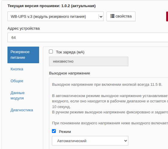
Affected devices
All WB-UPS v.3 before batch v3.3D/1.
Description
A production-test error left manual output-voltage control enabled instead of restoring the automatic default. Affected units therefore output 11.5 V regardless of voltage at Vin.
Workaround
- Set the appropriate mode using the device template in the controller web interface;
- Or manually write 0 to register 16 (0x0010, Output-voltage control mode).
Resolution
Fixed in batch v3.3D/1.
ERRWBUPS30002: Output-voltage setpoint freezes after input voltage dips and recovers
Affected devices
WB-UPS v.3 with firmware earlier than 1.4.1 in automatic output-voltage mode.
Description
In automatic mode, if input voltage drops below approximately 9.8 V and then recovers to approximately 12.0–12.4 V, requested and actual output-voltage setpoints (registers 11 and 13) remain frozen at their pre-dip values instead of tracking the input.
The frozen setpoint can be too low or too high:
- If below the shared bus voltage, the module supplies no load current and does not contribute power in parallel operation. This is the most noticeable symptom;
- If too high, output voltage remains above the level required for the current input.
This state persists indefinitely.
The fault occurs only when input voltage dips below approximately 9.8 V and then recovers to approximately 12.0–12.4 V. Stable input power, whether present or absent, does not trigger it. It is independent of parallel mode and load presence.
Cause and details
Automatic mode calculates input voltage minus 0.7 V with ±0.2 V hysteresis. Below 9.8 V, the hysteresis reference reset to the 11.5 V default and lost synchronization with the applied setpoint. If the recovered input remained within approximately 12.0–12.4 V, Vin minus 0.7 V stayed inside that hysteresis window, so no recalculation occurred and the setpoint remained frozen.
Workaround
- Move input voltage outside this range: above approximately 12.4 V or below approximately 12.0 V, accounting for cable and connector drops. The setpoint will then recalculate.
- Alternatively, select manual output-voltage mode and set the required value.
Resolution
Fixed in 1.4.1.
An input-voltage dip no longer changes the setpoint or resets the reference to its default. The first recalculation after input recovery is applied unconditionally and reinitializes the reference from the actual input voltage.