 Documentation
WB-MRWM2
Two-channel relay module with power measurement and voltage monitoring
Covered order codes (1)
WB-MRWM2
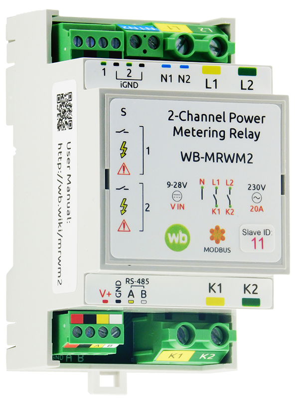
Purpose
WB-MRWM2 is designed for:
- switching high-power electrical loads up to 20 A, including inductive loads;
- measuring the root mean square (RMS) voltage;
- measuring active power;
- disconnecting the load when the voltage exceeds the permitted range; the limits are configured separately for each output.
The device also provides configurable:
- protective startup delays;
- restart delays;
- timer functions.
Delays and timers are configured separately for each output.
Two digital inputs provide direct control of the outputs.
The device requires a 9…28 V low-voltage power supply.
For relay selection, see Relay selection recommendations.
Technical specifications
| Parameter | Value |
|---|---|
| Power supply | |
| Supply voltage | 9–28 V DC |
| Measurement circuit supply voltage | 120…277 V AC |
| Power consumption |
|
| Outputs | |
| Number of outputs | 2 |
| Output type | Mechanical relay contacts |
| Contact configuration | On/off, normally open |
| Output arrangement | 2 outputs connected to relay contacts |
| Maximum switching voltage, AC | 250 V |
| Maximum switching voltage, DC | 30 V |
| Rated switching current per output at 230 V AC | 20 A |
| Maximum switching current per output at 230 V AC | 26 A |
| Maximum inrush current (20 ms) at 230 V AC | 80 A |
| Contact resistance | < 100 mΩ |
| Dielectric withstand voltage between relay coil and contacts | 4500 VAC (1 min) |
| Dielectric withstand voltage between open relay contacts | 2500 VAC (1 min) |
| Operating life | 30,000 switching cycles with a 20 A / 230 V AC load |
| Relay model | Hongfa HF161F-W |
| Inputs | |
| Number of inputs (Inputs 0–1) | 2 |
| Input type | Dry contact; inputs isolated as a group.
Input voltage approximately 12 V DC. Current with the input closed: ~2 mA |
| Permissible voltage | −20 V to +40 V |
| Pulse frequency and duration |
|
| Functions |
|
| Delays | |
| Protective startup delay | 0–999 s; default: 0 s |
| Restart delay | 0–999 s; default: 0 s |
| Active power measurement | |
| Minimum measurable power | 10 W |
| Measurement error | 2% over 20…100% of rated power |
| Root mean square (RMS) voltage measurement | |
| Minimum measurable voltage | 100 V AC |
| Measurement error | 2% at the nominal voltage of 230 V |
| Voltage monitoring | |
| Lower voltage limit | 120…220 V; default: 207 V |
| Upper voltage limit | 230…277 V; default: 242 V |
| Hysteresis | 4 V |
| Permitted voltage dip duration | 0.5…10 s; default: 5 s |
| Blocking response time | No more than 500 ms |
| Indicators | |
| LED | See Indicators |
| Control | |
| Control interface | RS-485 |
| Interface isolation | Non-isolated |
| Communication protocol | Modbus RTU; software-configurable address; factory settings are printed on the label |
| RS-485 interface parameters | Software-configurable; defaults:
baud rate — 9600 bit/s; data — 8 bits; parity — none (N); stop bits — 2 |
| Ready after power-on | ~2 s |
| Operating conditions | |
| Ambient air temperature | −40 to +80 °C |
| Relative humidity | Up to 95%, non-condensing |
| Climatic classification under GOST 15150-69 | O2.1* (the designation uses the Cyrillic letter O) |
| Warranty | 2 years |
| Service life | 8 years |
| Terminal blocks and wire cross-sections | |
| Recommended wire cross-section with insulated wire-end ferrules | control inputs: 0.35–1 mm2 — single ferrule; 0.35–0.5 mm2 — twin ferrule,
power terminals: up to 4 mm2 for single ferrules (up to 6 mm2 for solid conductors); up to 2.5 mm2 — twin ferrule |
| Standard ferrule sleeve length | control terminals: 8 mm;
power terminals: 10 mm |
| Screw tightening torque | control inputs: 0.2 N·m,
power outputs: 0.5 N·m |
| Dimensions | |
| Width, DIN modules | 3 |
| Overall dimensions (L × W × H) | 53 × 90 × 58 mm |
| Weight (including box) | 155 g |
Operating principle
Indicators
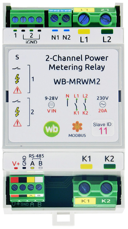
The module has 4 indicators:
 Status — green. Indicates Modbus communication: lights up when low-voltage power is applied, flashes during polling over RS-485, and flashes rapidly during a firmware upload;
 Relay — orange. Indicates the relay state; lights up when the relay contacts are closed;
 Power — orange. Flashes at a rate proportional to the power consumption. At 4.5 kW, it appears continuously lit;
 Phase fail — orange. Lights up when the voltage is outside the permitted range (configurable; default: 207…242 V).
Inputs
Inputs use numbered removable terminal blocks with a common iGND terminal and operate as dry-contact inputs.
Connect switches for direct output control, or a signal source for pulse counting and frequency measurement.
Both maintained and push buttones are supported. Push buttones support several press types, each of which can be assigned an action for scene control. Press events are also transmitted to the controller over Modbus for processing in software.
The Wiren Board controller does not poll press counters by default. Enable their polling in the device settings if required.
By default, each input controls the output with the same number. Input mode is Latching switch — the relay contacts follow the switch contacts. Change the switch type and input parameters in the settings.
Press-type recognition
The module recognises four press types: short; long; double; and short followed by long.
Presses can be processed on the controller, which receives a separate counter for each type over Modbus, or locally in the module to control its outputs.
Press-recognition parameters can be changed in the settings.
Outputs
The module has 2 independent normally open relay outputs.
The relays are certified for AC use only; their DC load capacity may be lower. For permitted load power and types, see Relay selection recommendations.
Power and voltage measurement
Each WB-MRWM2 output has a measurement circuit that measures:
- the root mean square (RMS) voltage;
- active power, measured correctly for capacitive, inductive and nonlinear loads.
The power reading update rate in the Modbus registers depends on the load power. It is lowest at low loads, when readings update once per second.
Different outputs of the device can be connected to different phases of a three-phase supply.
Delays
Protection Startup Delay (s) starts:
- when the device firmware starts (approximately 2.5 s after low-voltage power is applied);
- when the voltage returns to normal after voltage monitoring has blocked the output.
The delay reduces inrush currents by staggering the startup of loads.
Restart Delay After Output Turn Off (s) starts when the relay switches off. It protects loads sensitive to frequent switching, such as compressors and pumps.
Delays are configured separately for each relay output.
Output timer functions
Timer functions switch module outputs on or off according to a defined timing sequence.
Direct control and timer functions can be used in the same module. Each output can have only one timer function. Outputs are configured independently; changing one output does not affect the others. More about relay module timer functions.
Each relay output supports these timer functions: On-delay, Off-delay, Switch on for a time, Switch on for a time (with command reset), Switch off for a time, Switch off for a time (with command reset), ON/OFF cycle.
Voltage monitoring
This function is enabled separately for each output. The following settings are also configured individually: Overvoltage Threshold (V), Undervoltage Threshold (V) and Voltage Dip Duration (s).
If the measured output voltage exceeds the Overvoltage Threshold (V) or falls below 120 V, the output is blocked (switched off) immediately.
If the measured output voltage is above 120 V but below the Undervoltage Threshold (V) for longer than the Voltage Dip Duration (s), the output is blocked.
Blocking is released when the voltage returns within the permitted limits, allowing for the fixed hysteresis.
While blocked, the device accepts relay commands over Modbus and from inputs in Latching switch, Turn off all outputs and mapping-matrix modes. The last command is executed when blocking is released.
Safety Mode
Safety Mode allows processes to stop if control of the module is lost, for example because the RS-485 cable is damaged. Account for possible loss of communication with the controller when designing control systems. See Configuring Safety Mode.
Installation
Mount the device on a standard 35 mm DIN rail. The V+ GND A B terminal block, with a 3.5 mm pitch, connects the power supply and RS-485 communication bus. Correct bus wiring is essential for reliable communication; see RS-485 bus wiring and connection.
If devices on the RS-485 bus use different power supplies, their GND terminals must be interconnected. See Grounding Wiren Board devices and connecting GND and iGND.
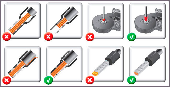
Use flexible stranded wire with insulated wire-end ferrules (NSHVI).
Strip the insulation to the sleeve length, or strip a little more and trim the protruding wire after crimping. Use a ferrule crimping tool. A crimped ferrule protects the strands from the screw clamp and secures the connection.
Do not overtighten the terminal screws: excessive force damages the screw terminal.
Relay switching briefly increases power consumption (see specifications). Choose a supply with adequate power reserve. For long supply cables, allow for the voltage drop along the cable.
Digital inputs activate when connected to iGND. The current is low (~2 mA), so any suitable button or switch type can be used. Cable length and cross-section are not critical for contact detection. To reduce interference from nearby power wiring, use twisted pair and connect iGND to the second conductor of the pair. More about connecting iGND/GND terminals.
The wire cross-section at relay output screw terminals must suit the switched load. The screw terminals accept wire cross-sections of 2.5–4 mm2.
Install the relay module in accordance with electrical safety requirements and prevent accidental contact with live high-voltage terminals. Operate it under the specified environmental conditions.
Installation example
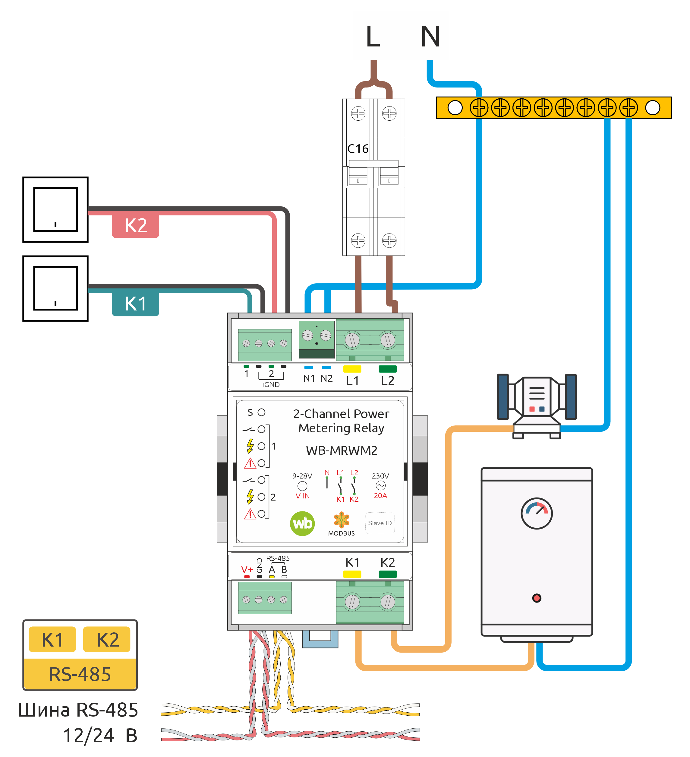
The figure shows one way to connect loads to WB-MRWM2 WB-MRWM2 installation example.
In this example, wiring upstream and downstream of the relay is protected by a 16 A circuit breaker. Select its rating according to the wire cross-section and the module's maximum switching current.
The diagram shows a water heater and an electric motor connected to outputs K1 and K2.
In this example, outputs K1 and K2 can be controlled both by switches and over RS-485. Input assignments can be changed using the mapping matrix.
For switch types and other module settings, see Configuration.
-
 WB-MRWM2 installation example
-
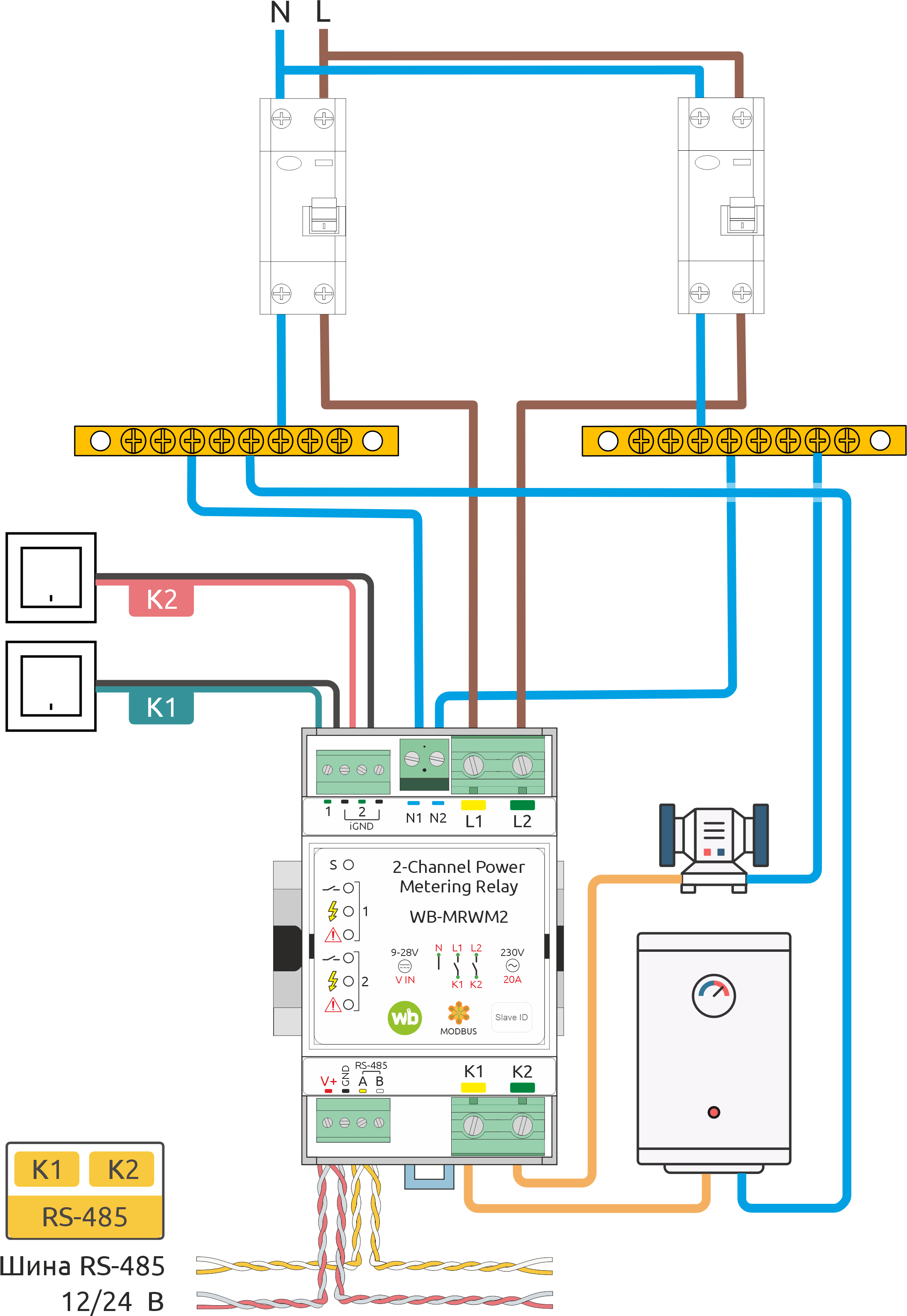 Using WB-MRWM2 with two RCBOs
Configuration
Configuration methods
- Set the parameters in the Wiren Board controller web interface under Settings → Configs → Serial devices driver configuration. If these items are unavailable, check your access level.
- Write settings to the Modbus registers of the module from the controller console using the utility modbus-utils-rpc or modbus_client.
- Without a Wiren Board controller, use the Wiren Board device web configurator or other software; see Using Wiren Board Modbus devices without a controller. You will need a computer with an interface converter: USB-RS485.
Our devices are continually improved. If settings described in this manual are missing, update the device firmware and controller software.
Input closure and press counters
The counters for input closures to ground are Input X counter. These counters are available in all modes for counting pulses and processing dry-contact signals.
When operating with the mapping matrix the following press-type counters are available:
- Single Press Counter — single short presses,
- Long Press Counter — long presses,
- Double Press Counter — double short presses,
- Shortlong Press Counter — short-then-long presses.
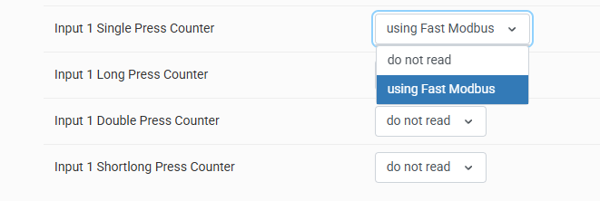
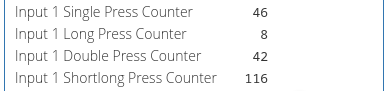
These count recognised press types, rather than input closures, and are intended for push-button processing. To use press types in wb-rules enable polling of the corresponding channels.
The counters Counter and Single Press Counter serve similar purposes but process contact closures differently:
- counter Counter increments as soon as the input closure is accepted after the configured debounce time;
- counter Single Press Counter increments when a short press has been detected without a second press. The response time is the short-press duration plus the second press waiting time.
Therefore, when using Single Press Counter to count digital signals, you may need to reduce the second press waiting time. For pulses and reed-switch activations, use Input Counter; use the button press counters when working with push buttons.
All counter values are stored in the relay microcontroller's RAM and reset when power is removed.
Control from switches
The parameter Operating mode lets you select the connected switch type, disable press actions, or select a mode based on the mapping matrix.
In matrix modes, input states and event counters can still be sent to the controller with input actions disabled, depending on channel polling settings.
Matrix modes are universal; switch modes are retained for compatibility with older projects.
When you select the mode Button mapping matrices lets you assign output actions to each of the four press types for scene control and multi-location switching. See Press-type recognition.
Available settings:
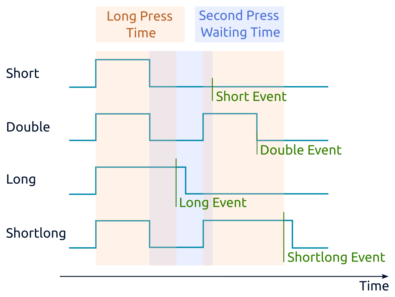
- Long Press Time (ms) — distinguishes long and short presses. A press lasting longer than this value is long; otherwise it is short.
- Second Press Waiting Time (ms) — opens a time window after a short press ends. A second press within this window is treated as a double press; otherwise the first press is treated as a single press.
- Debounce Time (ms) — the time for which the input signal must remain unchanged before it is registered and processed by the press recognition algorithm. For press recognition, set this to one-fifth to one-tenth of the second-press waiting time.
- Polling interval for each counter — leave this at the default value; the driver manages polling automatically.
Double-press recognition delays single-press recognition. With the default setting of 300 ms, a short-press event occurs 300 ms after the button is released. If double presses and short-then-long presses are not required, set Second press waiting time to 0 ms. The short-press event will then occur immediately after button release.
Press recognition takes place after debouncing. With Debounce time set to the default 50 ms, presses shorter than 50 ms are ignored. Button release is also registered 50 ms after physical release. Choose the debounce time for the particular button to minimise latency while preventing false events, such as a double press being detected instead of a single press.
Default input settings:
- each input controls the corresponding relay: for example, input 2 controls relay 2;
- input mode — latching switch.
Useful resources:
-
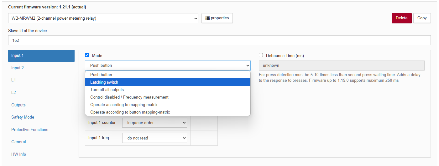 Selecting the mode for relay input 1
-
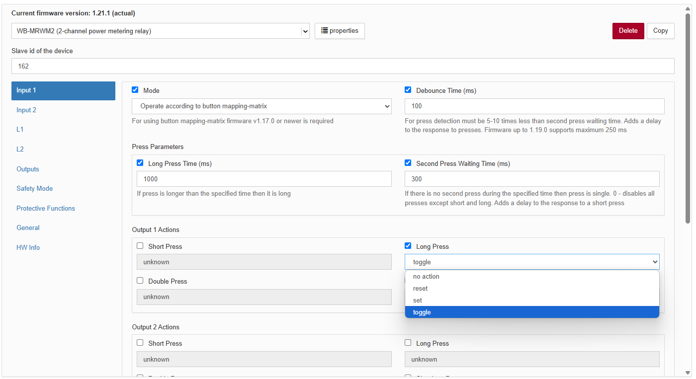 Assigning actions to press types
-
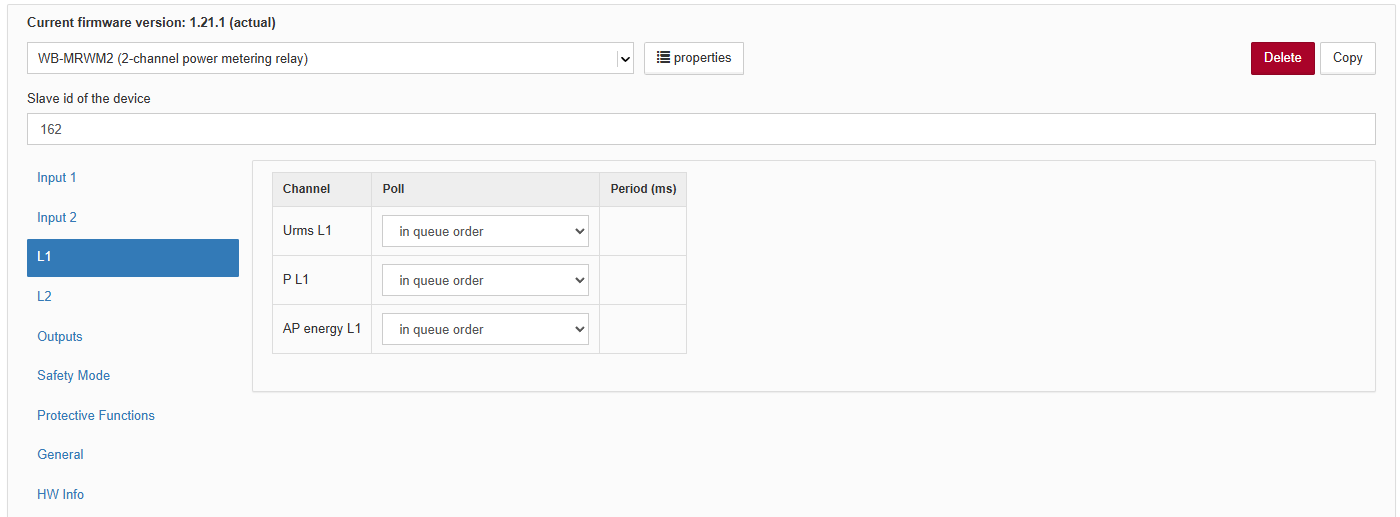 Configuring polling of channel L1
Debouncing
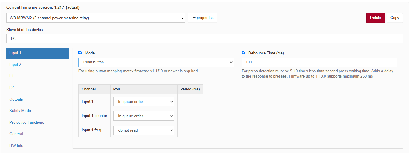
For any relay input, configure debouncing with the parameter Debounce Time (ms). Range: 0–2000 ms; default: 50 ms.
Output states at power-on
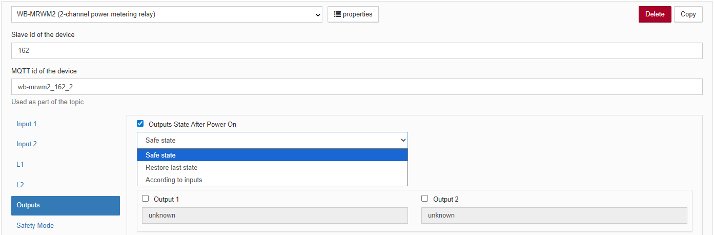
The following power-on behaviours are available:
- Set output to fail-safe state (default) — after power-on, outputs follow the setting Fail-safe output state;
- Restore last state — saves the last output states and restores them at power-on;
- Set according to input states — after power-on, outputs follow the input states (input N closed → output N on, where N is the input/output number). This only works with inputs in Latching switch mode.
Safety Mode
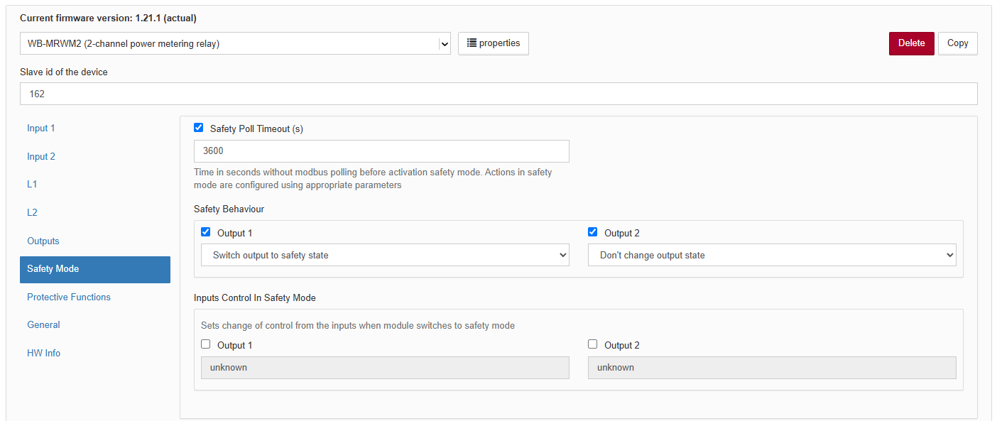
Safety Mode can stop a process if control of the module is lost, for example because the RS-485 cable is severed. Account for communication loss when designing control systems.
The fail-safe timer restarts after every successfully received and processed Modbus. When the configured time expires, the relay enters Safety Mode. Normal operation resumes when communication is restored. The default timeout is 10 seconds.
Each output has a configurable fail-safe state and can be configured to enter it on communication loss.
Input control behaviour can be configured:
- Do not block — previously enabled input control remains enabled.
- Block in safe mode — inputs cannot control the relays.
- Allow only in safe mode — input control blocked in normal operation becomes available in safe mode.
Configuring frequency measurement
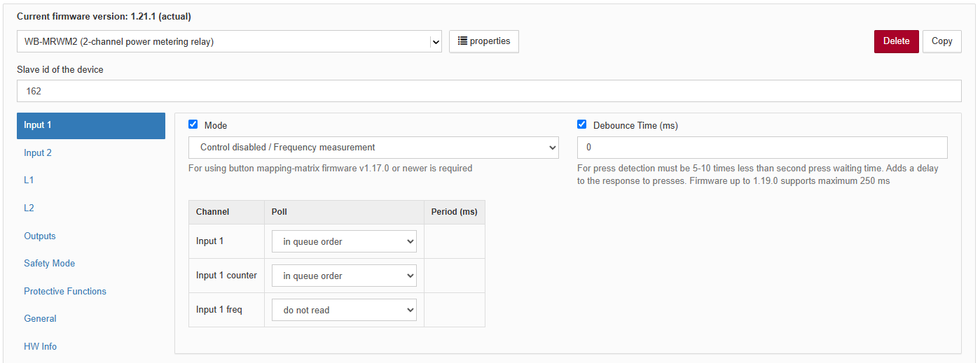
To measure the frequency of a signal at an input, configure that input as follows:
- Select the operating mode Control disabled, input measures frequency. This disconnects the input from output control.
- Set Debounce time to 0 ms to measure the highest supported frequencies. For low-frequency signals, the debounce time may instead be set below the pulse period.
- Disable polling of the input to reduce bus traffic.
For details of frequency register updates, see Updating frequency values in registers.
Protective Functions
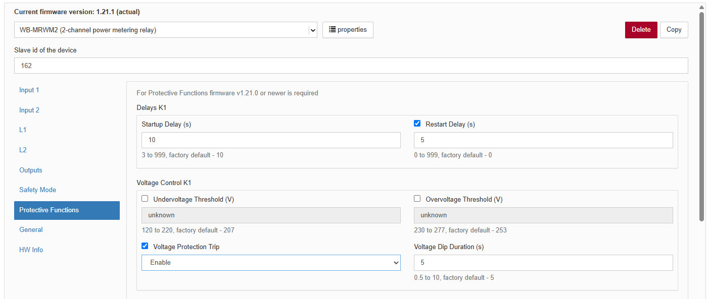
Delays
For each relay output, you can configure the Protection Startup Delay (s) and Restart Delay After Output Turn Off (s). Available range: 0…999 s; default: 0 s.
Voltage monitoring
Voltage monitoring settings are configured separately for each relay output:
- enable voltage blocking (enabled or disabled; disabled by default);
- lower voltage limit (120…220 V; default: 207 V);
- upper voltage limit (230…277 V; default: 242 V);
- permitted voltage dip duration (0.5…10 s; default: 5 s).
Configuring output timers
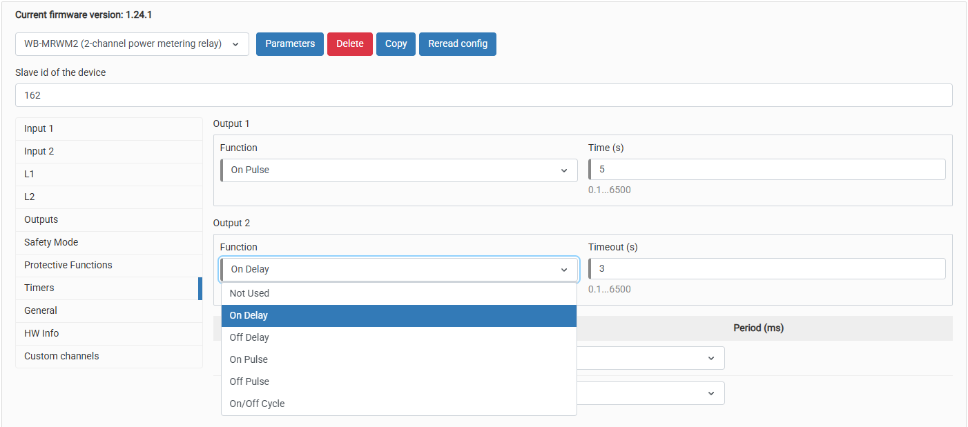
In the device settings, open Timers, select a function and configure its duration for the corresponding relay output.
Wiren Board controller web interface
Selecting a template
To display the device on the Devices tab of the Wiren Board controller web interface, add it automatically by scanning for Wiren Board devices on RS-485 or manually by selecting the template WB-MRWM2.
Controlling the device and viewing values
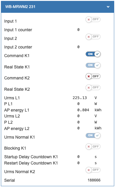
The web interface allows you to control device outputs and view readings. To change the displayed channels, edit the device configuration in the wb-mqtt-serial driver settings.
Measured values and controls:
- Input x — state of input x;
- Input x counter — closure counter for input x;
- Command Kx — command for output Kx;
- Real State Kx — actual state of output Kx;
- Urms Lx — RMS voltage of phase Lx, V;
- AP energy Lx — forward active energy for phase Lx, kWh;
- P Lx — forward active power for phase Lx, W;
- Voltage Status Kx — voltage monitoring status for phase Lx;
- Blocking Kx — blocking status of output Kx;
- Protection Startup Delay Kx — protective startup delay timer for output Kx;
- Restart Delay Kx — restart delay timer for output Kx.
Modbus operation
Wiren Board devices use Modbus RTU. The physical connection uses the RS-485.
interface. All main commands for reading and writing one or multiple registers are supported. See the list in the Modbus protocol description.
The module can be configured:
- in the Wiren Board controller web interface;
- using the Wiren Board device web configurator;
- using third-party software.
Default port settings
| Value default |
Parameter name in the web interface |
Parameter |
|---|---|---|
| 9600 | Baud rate | Baud rate, bit/s |
| 8 | Data bits | Number of data bits |
| None | Parity | Parity |
| 2 | Stop bits | Number of stop bits |
In current firmware, setting Stop bits is optional: the device also operates correctly when its number of stop bits differs from the Modbus master setting.
For a faster response, we recommend increasing the baud rate to 115200 bit/s; see Communication parameter settings.
Modbus address
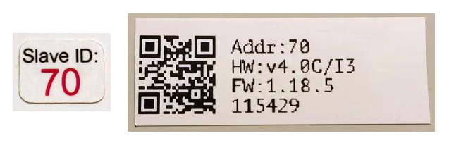
Each device on the bus must have a unique address from 1 to 247. The factory-assigned address is printed on labels on the enclosure (top cover, side or underside). Devices in a production batch are assigned different addresses, so devices in one order will usually have different addresses.
For instructions on finding, changing or resetting the address, see Wiren Board device Modbus address.
Fast Modbus extension
Fast Modbus extends standard Modbus with rapid discovery of Wiren Board devices on RS-485 and event polling.
These features are enabled by a special command from the master, so Wiren Board devices remain compatible with third-party equipment.
Not every register supports event generation. Check the register map: event-capable registers are marked with ⚡. See Fast Modbus.
Modbus register map
| RO / RW | Read only / Read/Write |
| Shown in bold | Default register value |
| xN | Multiply the register value by this factor to obtain the value in the stated units.
If omitted, assume 1 |
| ⚡ | This register supports data transmission using events in Fast Modbus. |
| FW | Firmware version that introduced the register. Blank means it has always been available. |
| Error: | Value on error |
| Grey cell | Service register: its purpose, format and contents may change in newer firmware versions |
| Address | Register parameters | Channel | Description | Values | FW | |||
|---|---|---|---|---|---|---|---|---|
| Dec | Hex | Type | Access | Format | ||||
| 56 | 0x0038 | Input | RO | u16 | Channel 1 | Voltage (RMS) | x0.01, V Error: 0 |
|
| 57 | 0x0039 | Channel 2 | ||||||
| 64 | 0x0040 | Input | RO | u16 | Channel 1 | Active power | ×0.1, W Error: 0 |
|
| 65 | 0x0041 | Channel 2 | ||||||
| 72 | 0x0048 | Input | RO | u32 | Channel 1 | Active energy | ×0.001, kWh Error: 0 |
|
| 74 | 0x004A | Channel 2 | ||||||
| 80 | 0x0050 | Discrete Input | RO | bool | Channel 1 | Voltage monitoring status | 0 — outside permitted limits 1 — normal |
1.21.0 |
| 81 | 0x0051 | Channel 2 | ||||||
| 88 | 0x0058 | Discrete Input | RO | bool | Channel 1 | Blocking status (a channel can be blocked by voltage monitoring or protective delays) | 0 — unblocked 1 — blocked |
1.21.0 |
| 89 | 0x0059 | Channel 2 | ||||||
| 340 | 0x0154 | Holding | RW | s16 | Channel 1 | Voltage calibration value | -32768...32767 (0) | |
| 341 | 0x0155 | Channel 2 | ||||||
| 348 | 0x015C | Holding | RW | s16 | Channel 1 | Power calibration value | -32768...32767 (0) | |
| 349 | 0x015D | Channel 2 | ||||||
| 360 - 361 | 0x0168 - 0x0169 | Input | RO | u32 | Channel 1 | Frequency from the chip's power measurement channel | x1.52588*10-05, Hz 0 |
|
| 364 - 365 | 0x016C - 0x016D | Channel 2 | ||||||
| 362 - 363 | 0x016A - 0x016B | Input | RO | u32 | Channel 1 | Frequency from the chip's voltage measurement channel | x1.52588*10-05, Hz 0 |
|
| 366 - 367 | 0x016E - 0x016F | Channel 2 | ||||||
| 368 - 369 | 0x0170 - 0x0171 | Input | RO | u32 | Channel 1 | Zero-crossing detector signal frequency | x1.52588*10-05, Hz 0 |
1.17.4 |
| 370 - 371 | 0x0172 - 0x0173 | Channel 2 | ||||||
| 1696 | 0x06A0 | Holding | RW | bool | Channel 1 | Voltage blocking | 0 — disabled 1 — enabled |
1.21.0 |
| 1697 | 0x06A1 | Channel 2 | ||||||
| 1704 | 0x06A8 | Holding | RW | u16 | Channel 1 | Lower voltage limit (×0.01, V) | 12000...22000 (20700) | 1.21.0 |
| 1705 | 0x06A9 | Channel 2 | ||||||
| 1712 | 0x06B0 | Holding | RW | u16 | Channel 1 | Upper voltage limit (×0.01, V) | 23000...27700 (24200) | 1.21.0 |
| 1713 | 0x06B1 | Channel 2 | ||||||
| 1720 | 0x06B8 | Holding | RW | u16 | Channel 1 | Permitted voltage dip duration (×0.1, s) | 5...100 (50) | 1.21.0 |
| 1721 | 0x06B9 | Channel 2 | ||||||
| RO / RW | Read only / Read/Write |
| Shown in bold | Default register value |
| xN | Multiply the register value by this factor to obtain the value in the stated units.
If omitted, assume 1 |
| ⚡ | This register supports data transmission using events in Fast Modbus. |
| FW | Firmware version that introduced the register. Blank means it has always been available. |
| Error: | Value on error |
| Grey cell | Service register: its purpose, format and contents may change in newer firmware versions |
| Address | Register parameters | Channel | Description | Values | FW | |||
|---|---|---|---|---|---|---|---|---|
| Dec | Hex | Type | Access | Format | ||||
| 0 | 0x0000 | Coil ⚡ | RW | bool | Channel 1 | Command Since FW 1.21.0, the command (requested relay state) and actual relay state are stored in separate registers because voltage blocking, delays or timers may cause them to differ |
0 — open, 1 — close |
|
| 1 | 0x0001 | Channel 2 | ||||||
| 2 | 0x0002 | Channel 3 | ||||||
| 3 | 0x0003 | Channel 4 | ||||||
| 4 | 0x0004 | Channel 5 | ||||||
| 5 | 0x0005 | Channel 6 | ||||||
| 100 | 0x0064 | Coil | WO | bool | Channel 1 | Turn off command | 1 — execute command | 1.24.0 |
| 101 | 0x0065 | Channel 2 | ||||||
| 102 | 0x0066 | Channel 3 | ||||||
| 103 | 0x0067 | Channel 4 | ||||||
| 104 | 0x0068 | Channel 5 | ||||||
| 105 | 0x0069 | Channel 6 | ||||||
| 108 | 0x006C | Coil | WO | bool | Channel 1 | Turn on command | 1 — execute command | 1.24.0 |
| 109 | 0x006D | Channel 2 | ||||||
| 110 | 0x006E | Channel 3 | ||||||
| 111 | 0x006F | Channel 4 | ||||||
| 112 | 0x0070 | Channel 5 | ||||||
| 113 | 0x0071 | Channel 6 | ||||||
| 116 | 0x0074 | Coil | WO | bool | Channel 1 | Toggle command | 1 — execute command | 1.24.0 |
| 117 | 0x0075 | Channel 2 | ||||||
| 118 | 0x0076 | Channel 3 | ||||||
| 119 | 0x0077 | Channel 4 | ||||||
| 120 | 0x0078 | Channel 5 | ||||||
| 121 | 0x0079 | Channel 6 | ||||||
| 0 | 0x0000 | Discrete input ⚡ |
RO | bool | Input 1 | Relay input state |
0 — open, |
|
| 1 | 0x0001 | Input 2 | ||||||
| 2 | 0x0002 | Input 3 | ||||||
| 3 | 0x0003 | Input 4 | ||||||
| 4 | 0x0004 | Input 5 | ||||||
| 5 | 0x0005 | Input 6 | ||||||
| 7 | 0x0007 | Input 0 | ||||||
| 4 | 0x0004 | Input | RW | u16 | External low-voltage power supply status (Only for relay modules with a built-in power supply) |
0 — external power supply not connected, |
1.18.4 | |
| 5 | 0x0005 | Holding | RW | u16 | Service register; must be 0 | 0 | ||
| 6 | 0x0006 | Holding | RW | u16 | Output states at power-up |
0 — set to the safe state, |
1.5.3 | |
| 8 | 0x0008 | Holding | RW | u16 | Communication loss timeout [s] | 1…65534 10 To disable Safety Mode, configure the Output action on entering Safety Mode and Input control in Safety Mode registers |
||
| 9 | 0x0009 | Holding | RW | u16 | Input 1 | Input operating mode. Register 5 must retain its default value (0). |
0 — momentary push buttons, |
|
| 10 | 0x000A | Input 2 | ||||||
| 11 | 0x000B | Input 3 | ||||||
| 12 | 0x000C | Input 4 | ||||||
| 13 | 0x000D | Input 5 | ||||||
| 14 | 0x000E | Input 6 | ||||||
| 16 | 0x0010 | Input 0 | Digital input 0 operating mode |
2 — turn off all outputs, |
1.9.0 | |||
| 19 | 0x0013 | Holding | RW | u16 | Fail-safe trigger selection. Only for WB-MR6C v.3 |
0 — communication loss or loss of low-voltage power 1 — loss of low-voltage power 2 — communication loss |
1.18.4 | |
| 20 | 0x0014 | Holding | RW | u16 | Input 1 | Debounce time [ms] | 0…2000 (50) 0…250 (50) before FW 1.19.0 0…100 (50) before FW 1.17.8 |
1.13.0 |
| 21 | 0x0015 | Input 2 | ||||||
| 22 | 0x0016 | Input 3 | ||||||
| 23 | 0x0017 | Input 4 | ||||||
| 24 | 0x0018 | Input 5 | ||||||
| 25 | 0x0019 | Input 6 | ||||||
| 27 | 0x001B | Input 0 | ||||||
| 32 | 0x0020 | Input ⚡ | RO | u16 | Input 1 | Input closure counter | 0…65535, wraps around Error: 0 |
|
| 33 | 0x0021 | Input 2 | ||||||
| 34 | 0x0022 | Input 3 | ||||||
| 35 | 0x0023 | Input 4 | ||||||
| 36 | 0x0024 | Input 5 | ||||||
| 37 | 0x0025 | Input 6 | ||||||
| 39 | 0x0027 | Input 0 | ||||||
| 40 | 0x0028 | Input | RO | u32 | Input 1 | Integer part of signal frequency | x1.52588 x 10−5, Hz Error: 0 |
1.15.0 |
| 42 | 0x002A | Input 2 | ||||||
| 44 | 0x002C | Input 3 | ||||||
| 46 | 0x002E | Input 4 | ||||||
| 48 | 0x0030 | Input 5 | ||||||
| 50 | 0x0032 | Input 6 | ||||||
| 54 | 0x0036 | Input 0 | ||||||
| 41 | 0x0029 | Input | RO | u16 | Input 1 | Fractional part of the signal frequency: 1 Hz = 65536 (216) | Error: 0 | |
| 43 | 0x002B | Input 2 | ||||||
| 45 | 0x002D | Input 3 | ||||||
| 47 | 0x002F | Input 4 | ||||||
| 49 | 0x0031 | Input 5 | ||||||
| 51 | 0x0033 | Input 6 | ||||||
| 55 | 0x0037 | Input 0 | ||||||
| 96 | 0x0060 | Discrete input ⚡ |
RO | bool | Channel 1 | Actual relay state | 0 — open, 1 — closed |
1.21.0 |
| 97 | 0x0061 | Channel 2 | ||||||
| 98 | 0x0062 | Channel 3 | ||||||
| 99 | 0x0063 | Channel 4 | ||||||
| 100 | 0x0064 | Channel 5 | ||||||
| 101 | 0x0065 | Channel 6 | ||||||
| 464 | 0x01D0 | Input ⚡ | RO | u16 | Input 1 | Short-press counter | 0…65535, wraps around | 1.17.0 |
| 465 | 0x01D1 | Input 2 | ||||||
| 466 | 0x01D2 | Input 3 | ||||||
| 467 | 0x01D3 | Input 4 | ||||||
| 468 | 0x01D4 | Input 5 | ||||||
| 469 | 0x01D5 | Input 6 | ||||||
| 471 | 0x01D7 | Input 0 | ||||||
| 480 | 0x01E0 | Input ⚡ | RO | u16 | Input 1 | Long-press counter | 0…65535, wraps around | |
| 481 | 0x01E1 | Input 2 | ||||||
| 482 | 0x01E2 | Input 3 | ||||||
| 483 | 0x01E3 | Input 4 | ||||||
| 484 | 0x01E4 | Input 5 | ||||||
| 485 | 0x01E5 | Input 6 | ||||||
| 487 | 0x01E7 | Input 0 | ||||||
| 496 | 0x01F0 | Input ⚡ | RO | u16 | Input 1 | Double-press counter | 0…65535, wraps around | |
| 497 | 0x01F1 | Input 2 | ||||||
| 498 | 0x01F2 | Input 3 | ||||||
| 499 | 0x01F3 | Input 4 | ||||||
| 500 | 0x01F4 | Input 5 | ||||||
| 501 | 0x01F5 | Input 6 | ||||||
| 503 | 0x01F7 | Input 0 | ||||||
| 512 | 0x0200 | Input ⚡ | RO | u16 | Input 1 | Short-then-long-press counter | 0…65535, wraps around | |
| 513 | 0x0201 | Input 2 | ||||||
| 514 | 0x0202 | Input 3 | ||||||
| 515 | 0x0203 | Input 4 | ||||||
| 516 | 0x0204 | Input 5 | ||||||
| 517 | 0x0205 | Input 6 | ||||||
| 519 | 0x0207 | Input 0 | ||||||
| 384 - 447 | 0x0180 - 0x01BF | Holding | RW | u16 | Registers of the mapping matrix | 0 | 1.9.0 | |
| 544 - 607 | 0x0220 - 0x025F | Holding | RW | u16 | Registers of the mapping matrix for short presses | 0 | 1.17.0 | |
| 608 - 671 | 0x0260 - 0x029F | Holding | RW | u16 | Registers of the mapping matrix for long presses | 0 | ||
| 672 - 735 | 0x02A0 - 0x02DF | Holding | RW | u16 | Registers of the mapping matrix for double presses | 0 | ||
| 736 - 799 | 0x02E0 - 0x031F | Holding | RW | u16 | Registers of the mapping matrix for short-then-long presses | 0 | ||
| 800 - 863 | 0x0320 - 0x035F | Holding | RW | u16 | Registers of the mapping matrix for button release | 0 | 1.19.0 | |
| 864 - 927 | 0x0360 - 0x039F | Holding | RW | u16 | Registers of the mapping matrix for button closure | 0 | ||
| 930 | 0x03A2 | Holding | RW | u16 | Channel 1 | Fail-safe output state setting |
0 — off (NO contacts open) |
1.18.4 |
| 931 | 0x03A3 | Channel 2 | ||||||
| 932 | 0x03A4 | Channel 3 | ||||||
| 933 | 0x03A5 | Channel 4 | ||||||
| 934 | 0x03A6 | Channel 5 | ||||||
| 935 | 0x03A7 | Channel 6 | ||||||
| 938 | 0x03AA | Holding | RW | u16 | Channel 1 | Output action on entering Safety Mode |
0 — do nothing |
1.18.4 |
| 939 | 0x03AB | Channel 2 | ||||||
| 940 | 0x03AC | Channel 3 | ||||||
| 941 | 0x03AD | Channel 4 | ||||||
| 942 | 0x03AE | Channel 5 | ||||||
| 943 | 0x03AF | Channel 6 | ||||||
| 946 | 0x03B2 | Holding | RW | u16 | Channel 1 | Input control in Safety Mode |
0 — do not block |
1.18.4 |
| 947 | 0x03B3 | Channel 2 | ||||||
| 948 | 0x03B4 | Channel 3 | ||||||
| 949 | 0x03B5 | Channel 4 | ||||||
| 950 | 0x03B6 | Channel 5 | ||||||
| 951 | 0x03B7 | Channel 6 | ||||||
| 1100 | 0x044C | Holding | RW | u16 | Input 1 | Long press time [ms]. A press longer than this interval is treated as a long press |
500…5000 (1000) | 1.17.0 |
| 1101 | 0x044D | Input 2 | ||||||
| 1102 | 0x044E | Input 3 | ||||||
| 1103 | 0x044F | Input 4 | ||||||
| 1104 | 0x0450 | Input 5 | ||||||
| 1105 | 0x0451 | Input 6 | ||||||
| 1107 | 0x0453 | Input 0 | ||||||
| 1140 | 0x0474 | Holding | RW | u16 | Input 1 | Second press waiting time [ms]. If no second press occurs within the specified time, the press is treated as a single press. Set to 0 to disable all press types except short and long presses |
0…2000 (300) | |
| 1141 | 0x0475 | Input 2 | ||||||
| 1142 | 0x0476 | Input 3 | ||||||
| 1143 | 0x0477 | Input 4 | ||||||
| 1144 | 0x0478 | Input 5 | ||||||
| 1145 | 0x0479 | Input 6 | ||||||
| 1147 | 0x047B | Input 0 | ||||||
| Timer functions | ||||||||
| 1760 | 0x06E0 | Holding | RW | u16 | Channel 1 | Timer function | 0 — not used 1 — On Delay 2 — Off Delay 3 — Turn On For The Specified Time 4 — Turn Off For The Specified Time 5 — On/Off Cycle 6 — Turn On For The Specified Time (with command reset) 7 — Turn Off For The Specified Time (with command reset) Values 6 and 7 are available from FW 1.27.0 |
1.24.0 |
| 1761 | 0x06E1 | Channel 2 | ||||||
| 1762 | 0x06E2 | Channel 3 | ||||||
| 1763 | 0x06E3 | Channel 4 | ||||||
| 1764 | 0x06E4 | Channel 5 | ||||||
| 1765 | 0x06E5 | Channel 6 | ||||||
| 1768 | 0x06E8 | Holding | RW | u16 | Channel 1 | On-delay (×0.1 s) | 1…65000 (30) | 1.24.0 |
| 1769 | 0x06E9 | Channel 2 | ||||||
| 1770 | 0x06EA | Channel 3 | ||||||
| 1771 | 0x06EB | Channel 4 | ||||||
| 1772 | 0x06EC | Channel 5 | ||||||
| 1773 | 0x06ED | Channel 6 | ||||||
| 1776 | 0x06F0 | Holding | RW | u16 | Channel 1 | Off-delay (×0.1 s) | 1…65000 (30) | 1.24.0 |
| 1777 | 0x06F1 | Channel 2 | ||||||
| 1778 | 0x06F2 | Channel 3 | ||||||
| 1779 | 0x06F3 | Channel 4 | ||||||
| 1780 | 0x06F4 | Channel 5 | ||||||
| 1781 | 0x06F5 | Channel 6 | ||||||
| 1784 | 0x06F8 | Holding | RW | u16 | Channel 1 | Switch on for a time (×0.1 s) | 1…65000 (30) | 1.24.0 |
| 1785 | 0x06F9 | Channel 2 | ||||||
| 1786 | 0x06FA | Channel 3 | ||||||
| 1787 | 0x06FB | Channel 4 | ||||||
| 1788 | 0x06FC | Channel 5 | ||||||
| 1789 | 0x06FD | Channel 6 | ||||||
| 1792 | 0x0700 | Holding | RW | u16 | Channel 1 | Switch off for a time (×0.1 s) | 1…65000 (30) | 1.24.0 |
| 1793 | 0x0701 | Channel 2 | ||||||
| 1794 | 0x0702 | Channel 3 | ||||||
| 1795 | 0x0703 | Channel 4 | ||||||
| 1796 | 0x0704 | Channel 5 | ||||||
| 1797 | 0x0705 | Channel 6 | ||||||
| 1800 | 0x0708 | Holding | RW | u16 | Channel 1 | ON cycle duration (s) | 1…65000 (3) | 1.24.0 |
| 1801 | 0x0709 | Channel 2 | ||||||
| 1802 | 0x070A | Channel 3 | ||||||
| 1803 | 0x070B | Channel 4 | ||||||
| 1804 | 0x070C | Channel 5 | ||||||
| 1805 | 0x070D | Channel 6 | ||||||
| 1808 | 0x0710 | Holding | RW | u16 | Channel 1 | OFF cycle duration (s) | 1…65000 (3) | 1.24.0 |
| 1809 | 0x0711 | Channel 2 | ||||||
| 1810 | 0x0712 | Channel 3 | ||||||
| 1811 | 0x0713 | Channel 4 | ||||||
| 1812 | 0x0714 | Channel 5 | ||||||
| 1813 | 0x0715 | Channel 6 | ||||||
| 1864 | 0x0748 | Input | RO | u16 | Channel 1 | Remaining time of the active timer | ×0.1 s (functions 1–4, 6 and 7) ×1 s (function 5) Error: 0 |
1.24.0 |
| 1865 | 0x0749 | Channel 2 | ||||||
| 1866 | 0x074A | Channel 3 | ||||||
| 1867 | 0x074B | Channel 4 | ||||||
| 1868 | 0x074C | Channel 5 | ||||||
| 1869 | 0x074D | Channel 6 | ||||||
| Delays | ||||||||
| 1728 | 0x06C0 | Holding | RW | u16 | Channel 1 | Protective startup delay (×0.1, s) | 0...9990 (0) | 1.21.0 |
| 1729 | 0x06C1 | Channel 2 | ||||||
| 1730 | 0x06C2 | Channel 3 | ||||||
| 1731 | 0x06C3 | Channel 4 | ||||||
| 1732 | 0x06C4 | Channel 5 | ||||||
| 1733 | 0x06C5 | Channel 6 | ||||||
| 1736 | 0x06C8 | Holding | RW | u16 | Channel 1 | Restart delay (×0.1 s) | 0...9990 (0) | 1.21.0 |
| 1737 | 0x06C9 | Channel 2 | ||||||
| 1738 | 0x06CA | Channel 3 | ||||||
| 1739 | 0x06CB | Channel 4 | ||||||
| 1740 | 0x06CC | Channel 5 | ||||||
| 1741 | 0x06CD | Channel 6 | ||||||
| 1744 | 0x06D0 | Input | RO | u16 | Channel 1 | Protective startup delay timer (×0.1, s) | x0.1, c Error: 0 |
1.21.0 |
| 1745 | 0x06D1 | Channel 2 | ||||||
| 1746 | 0x06D2 | Channel 3 | ||||||
| 1747 | 0x06D3 | Channel 4 | ||||||
| 1748 | 0x06D4 | Channel 5 | ||||||
| 1749 | 0x06D5 | Channel 6 | ||||||
| 1752 | 0x06D8 | Input | RO | u16 | Channel 1 | Restart delay timer | x0.1, c Error: 0 |
1.21.0 |
| 1753 | 0x06D9 | Channel 2 | ||||||
| 1754 | 0x06DA | Channel 3 | ||||||
| 1755 | 0x06DB | Channel 4 | ||||||
| 1756 | 0x06DC | Channel 5 | ||||||
| 1757 | 0x06DD | Channel 6 | ||||||
| Address | Register parameters | Description | Values | Note | |||
|---|---|---|---|---|---|---|---|
| Dec | Hex | Type | Access | Format | |||
| Connection settings | |||||||
| 110 | 0x006E | Holding | RW | u16 | RS-485 baud rate. RS-485 connection parameter settings |
×100, baud 12 — 1200 bit/s, 24 — 2400 bit/s, 48 — 4800 bit/s, 96 — 9600 bit/s, 192 — 19200 bit/s, 384 — 38400 bit/s, 576 — 57600 bit/s, 1152 — 115200 bit/s |
|
| 111 | 0x006F | Holding | RW | u16 | RS-485 parity setting | 0 — no parity (none), 1 — odd, 2 — even |
|
| 112 | 0x0070 | Holding | RW | u16 | RS-485 stop bits See: stop-bit tolerance |
1, 2 | |
| 128 | 0x0080 | Holding | RW | u16 | Device Modbus address (details) | ||
| Device model and firmware version | |||||||
| 200-205 | 0x00C8 - 0x00CD | Input | RO | string | Device model | ||
| 206-219 | 0x00CE - 0x00DB | Input | RO | string | Device model extension. | Read 20 registers (200–219) to obtain the device model | Only in firmware supporting Fast Modbus |
| 220-244 | 0x00DC - 0x00F4 | Input | RO | string | Firmware build commit hash and branch name (2 characters per register) | ||
| 250-265 | 0x00FA - 0x0109 | Input | RO | string | Firmware version | ||
| 266-269 | 0x010A - 0x010D | Input | RO | u64 | Serial number extension | ||
| 270-271 | 0x010E - 0x010F | Input | RO | u32 | Serial number | ||
| 290-301 | 0x0122 - 0x012D | Input | RO | string | Firmware signature | ||
| 320 | 0x0140 | Input | RO | u16 | Firmware version in numeric format (details) | MAJOR | Only in firmware supporting Fast Modbus |
| 321 | 0x0141 | MINOR | |||||
| 322 | 0x0142 | PATCH | |||||
| 323 | 0x0143 | s16 | SUFFIX | ||||
| 324-325 | 0x0144 - 0x0145 | Input | RO | u32 | Firmware version in numeric format | Only in firmware supporting Fast Modbus | |
| 326-327 | 0x0146 - 0x0147 | Input | RO | u32 | Firmware version in big-endian format | Only in firmware supporting Fast Modbus | |
| Other information | |||||||
| 104-105 | 0x0068 - 0x0069 | Input | RO | u32 | Uptime since boot | seconds | |
| 120 | 0x0078 | Holding | RW | u16 | Reboot device without saving state | Any non-zero value reboots the device | |
| 129 | 0x0081 | Holding | RW | u16 | Enter firmware update mode for 2 minutes | Any non-zero value enters firmware update mode | |
| 330-337 | 0x014A - 0x0151 | Input | RO | string | Bootloader version | ||
| 130 | 0x0082 | Holding | RW | u16 | Disable Status LED | 0 — enabled 1 — disabled |
|
| 131 | 0x0083 | Holding | RW | u16 | Enter firmware update mode using the current communication settings. To check whether the firmware and bootloader support this feature, read this register. If reading succeeds and returns 0, the feature is supported.
|
Writing 1 enters firmware update mode | |
| 113 | 0x0071 | Holding | RW | u16 | Delay before sending a response to a Modbus request | ms 0…254 (0) |
Only in firmware supporting Fast Modbus |
| 114 | 0x0072 | Holding | RW | u16 | Continuous reading across register gaps | 0 — disabled 1 — enabled 2 — enabled persistently across reboots |
Only in firmware supporting Fast Modbus |
| 121 | 0x0079 | Input | RO | u16 | Current supply voltage | mV | |
| 122 | 0x007A | Input | RO | u16 | Minimum supply voltage since boot, without averaging | mV | |
| 125 | 0x007D | Input | RO | u16 | Current supply voltage, without averaging | mV | |
| 119 | 0x0077 | Input | RO | u16 | Minimum microcontroller supply voltage since boot, before averaging | mV | |
| 123 | 0x007B | Input | RO | u16 | Microcontroller supply voltage | mV | |
| 124 | 0x007C | Input | RO | s16 | Internal microcontroller temperature | x0.1, °C | |
| 304-319 | 0x0130-0x013F | Input | RO | string | Device batch number.
Available only on devices manufactured from 21 January 2026. |
From firmware 1.23.0 | |
| 64256-64383 | 0xFB00-0xFB7F | Input | RO | u16 | FlashFS: free space per page | bytes | From firmware 1.23.0 |
| 64384-64511 | 0xFB80-0xFBFF | Input | RO | u16 | FlashFS: total size of current files per page | bytes | |
| 64512-64639 | 0xFC00-0xFC7F | Input | RO | u16 | FlashFS: page fragmentation | 0…100 % 0 — all data is current, 100 — no current data | |
| 64640-64767 | 0xFC80-0xFCFF | Input | RO | u16 | FlashFS: page erase counter | ||
| 65402 | 0xFF7A | Holding | RW | u16 | Reset device settings to defaults. Communication settings are retained. The device reboots after the reset. |
Writing 1 resets the settings | From firmware 1.22.0 |
| 65500 | 0xFFDC | Coil | RW | bool | Service register for visually testing indicator LEDs | Writing 1 switches on all indicator LEDs | Since firmware 1.25.0 |
| 65504 | 0xFFE0 | Input | RO | u16 | Maximum stack usage | bytes 0 — stack corrupted |
From firmware 1.23.0 |
| 65505 | 0xFFE1 | Input | RO | u16 | Free RAM | bytes | |
| 65506 | 0xFFE2 | Input | RO | u16 | Used RAM | bytes | |
| 65507 | 0xFFE3 | Input | RO | u16 | Stack size | bytes | |
| 65508 | 0xFFE4 | Input | RO | u16 | Cause of last MCU reset | 1 — LPWR, 2 — WWDG, 3 — IWDG, 4 — SFT, 5 — POR, 6 — PIN, 7 — OBL, 8 — V18PWR |
From firmware 1.23.0 |
| 65509 | 0xFFE5 | Input | RO | u32 | Firmware update counter | From firmware 1.23.0 | |
| 65511 | 0xFFE7 | Input | RO | u16 | MCU memory capacity | High byte: flash capacity code; capacity in KB = 16 × 2code; Low byte: RAM capacity in KB. Example: 0x0208 (520) — 64 KB flash, 8 KB RAM |
Since firmware 1.27.1 |
Firmware updates and resetting settings
Wiren Board devices support firmware updates over Modbus. This allows bugs to be fixed at the installation site and, where technically possible, new features to be added. Settings stored in the device are retained during a firmware update.
Instructions:
- Firmware update ()
- Resetting settings
- Connection parameter settings
- Modbus address: find, reset or change
- Updating the bootloader
New firmware releases are listed in the device firmware changelog.
Known issues
ERRMRWM0001 — Energy accumulation is unavailable in firmware 1.19.0 through 1.20.1 inclusive; the energy register remains at 0. Update to firmware 1.20.2 or later.
ERRMR17 — Hardware batches v1.4B–v1.5C may consume more power and run warmer with relays on. This was corrected in batch v1.5D. A 12 V supply reduces heating where suitable; contact support if the module becomes unusually hot.
Hardware revisions
| Revision | Batches | Release date | Changes from the previous revision |
|---|---|---|---|
| 1.7 | v1.7D, v1.7E, v1.7E/1, v1.7F - ... | 08.2025 - ... |
|
| 1.7 | v1.7A, v1.7A/1, v1.7B, v1.7C, v1.7C/1 | 08.2024 - 08.2025 |
|
| 1.5 | v1.5E | 02.2024 - 07.2024 |
|
| 1.5 | v1.5A, v1.5B, v1.5C, v1.5D, v1.5E/1 | 02.2023 - 02.2024 |
|
| 1.4 | v1.4A, v1.4A/1, v1.4B, v1.4B/1 | 03.2022 - 12.2022 |
|
Troubleshooting
Interference from relays and contactors
Relays and contactors can interfere with nearby devices. When switching loads, especially inductive loads, the contacts generate high-frequency transients with amplitudes of several kilovolts, which may couple into other circuits. Snubber networks suppress these transients, reducing interference and improving equipment stability. See Interference when switching inductive loads
Images and drawings
-
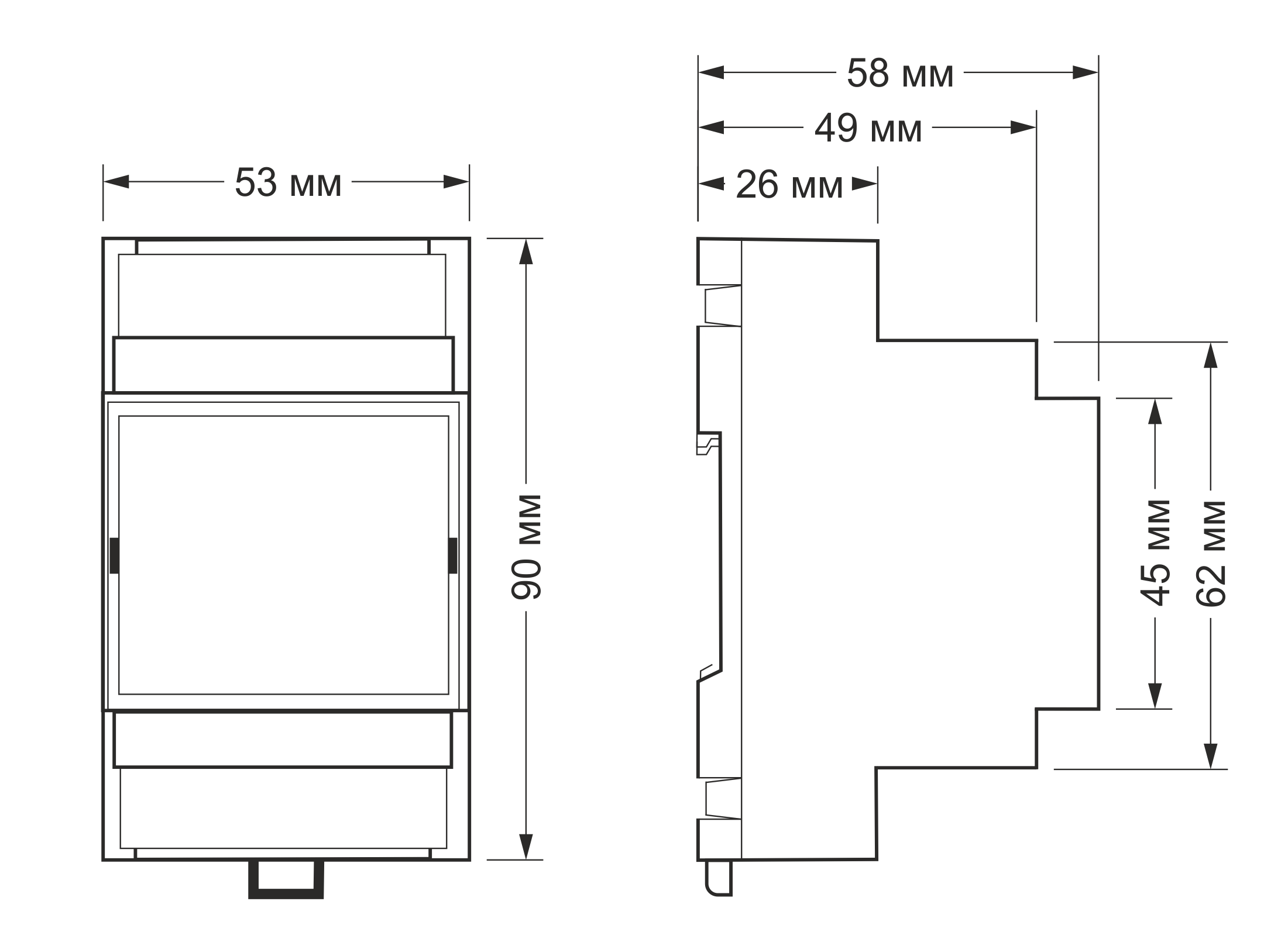 Overall dimensions: 53.3 × 90.2 × 57.5 mm (L × W × H)
Images and diagrams for earlier hardware versions
-
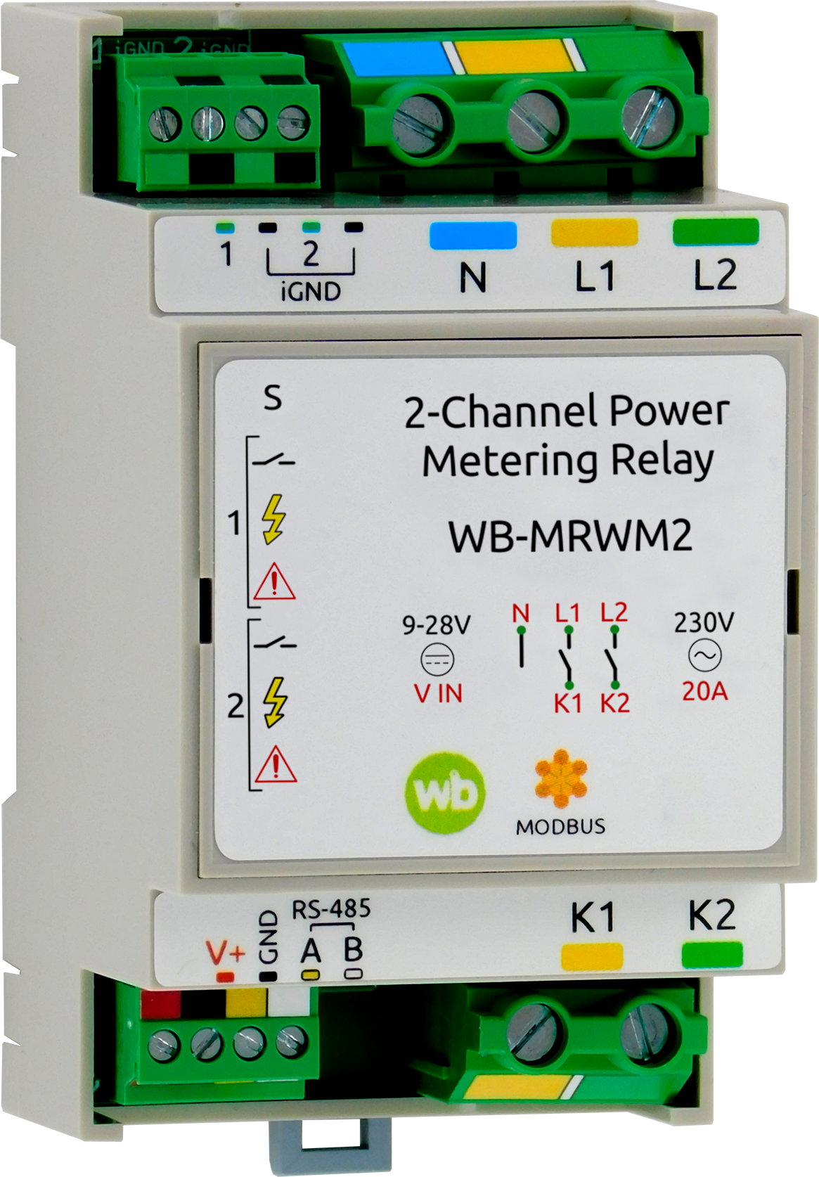 WB-MRWM2 relay module before version v1.7
-
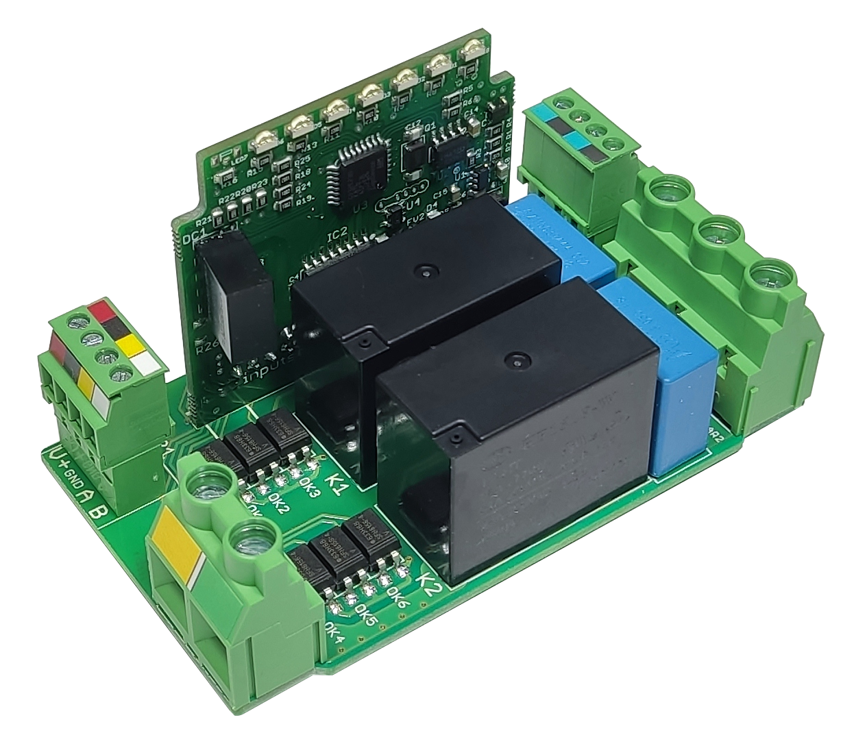 WB-MRWM2 circuit board before version v1.7
-
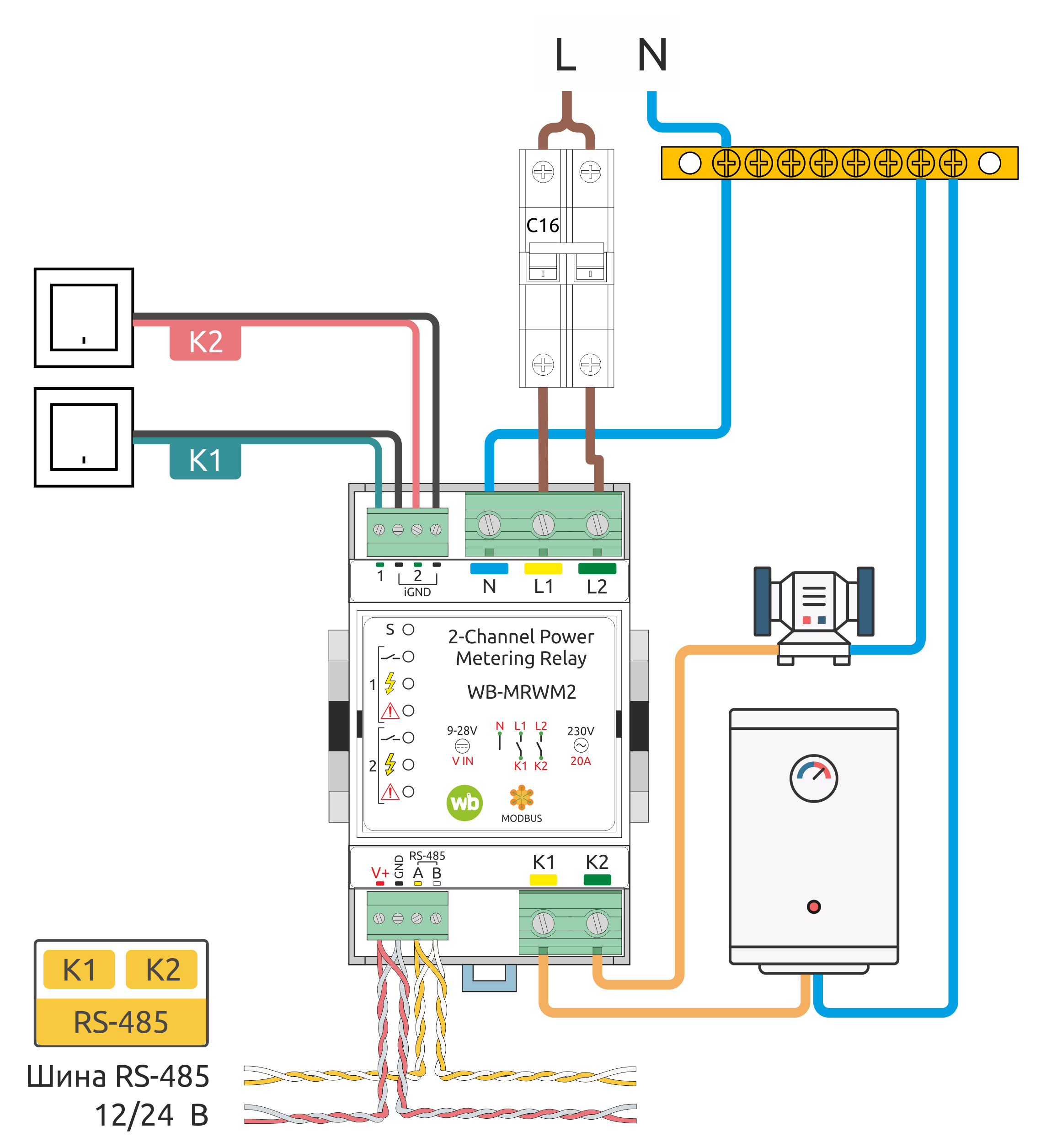 WB-MRWM2 installation example before version v1.7