Documentation
WB-MR6CU v.2
Compact 6-channel RS-485 Modbus RTU relay module
Covered order codes (1)
WB-MR6CU v.2— Compact 6-channel RS-485 Modbus RTU relay module
Purpose
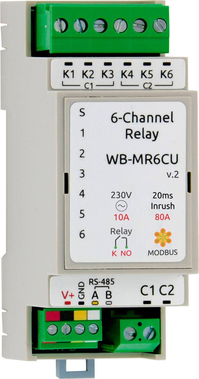
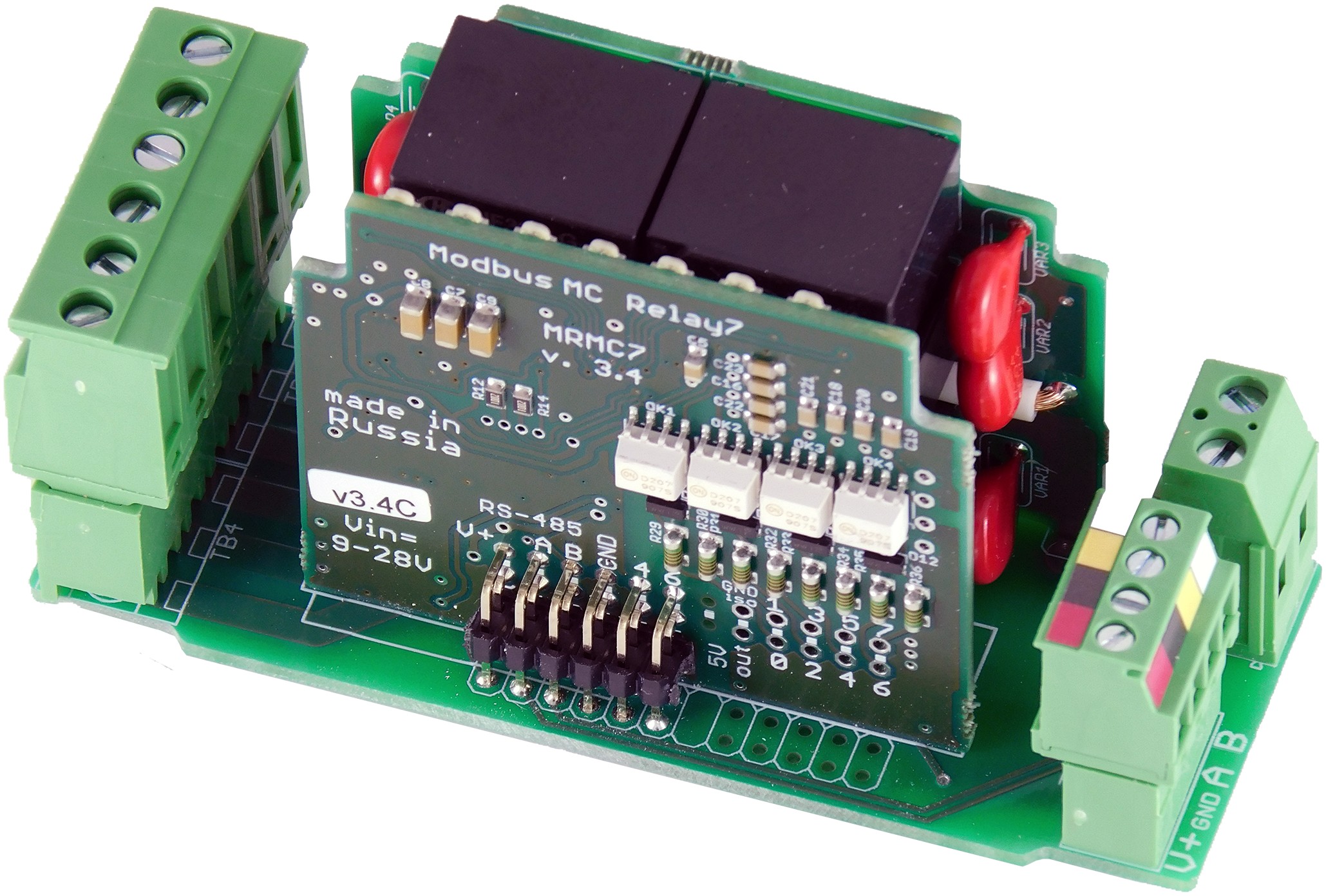
WB-MR6CU v.2 is a six-channel relay module for industrial and home automation. It directly controls LED and fluorescent luminaires, incandescent lamps and other loads rated up to 10 A (2 kW). It can also be used as a general-purpose output module.
Each output can withstand continuous current up to 16 A and inrush current up to 80 A. Because of the terminal-block design, the total rated switching current for each group of three outputs is 20 A.
Select the relay module and load protection according to the load type, steady-state current and inrush current.
Changes from the previous version
Difference from WB-MR6CU v.1:
- WB-MR6CU v.2 uses higher-capacity relays; the maximum switching current of each output is 16 A at 230 VAC.
Technical specifications
| Parameter | Value |
|---|---|
| Power supply | |
| Supply voltage | 9–28 V DC |
| Power consumption |
|
| Outputs | |
| Number of outputs | 6 |
| Output type | Mechanical relay contacts |
| Contact configuration | On/off, normally open |
| Output arrangement | Two groups of three outputs, with a common terminal for each group |
| Maximum switching voltage, AC | 250 V |
| Maximum switching voltage, DC | 30 V |
| Rated switching current per output at 230 V AC | 10 A |
| Maximum switching current per output at 230 V AC | 16 A |
| Maximum inrush current (20 ms) at 230 V AC | 80 A |
| Total rated switching current per group of three relay outputs at 230 V AC | 20 A |
| Contact resistance | < 100 mΩ |
| Contact material | AgSnO2 |
| Dielectric withstand voltage between relay coil and contacts | 4000 V AC (1 minute) |
| Dielectric withstand voltage between open relay contacts | 1000 V AC (1 minute) |
| Operating life | 100000 operations with a 10 A / 230 V AC load |
| Detailed specifications | HF32FV-16/5-HLTF(590) |
| Datasheet | HF32FV-16.pdf |
| Inputs | |
| Number of inputs | No inputs |
| Delays | |
| Startup Delay When Power On (s) | 0–999 s; default: 0 s |
| Restart Delay After Output Turn Off (s) | 0–999 s; default: 0 s |
| Indicators | |
| LED | See the Indicators section |
| Control | |
| Control interface | RS-485 |
| Interface isolation | Non-isolated |
| Communication protocol | Modbus RTU; software-configurable address; factory settings are printed on the label |
| RS-485 interface parameters | Software-configurable; defaults:
baud rate — 9600 bit/s; data — 8 bits; parity — none (N); stop bits — 2 |
| Ready after power-on | ~2 s |
| Operating conditions | |
| Ambient air temperature | −40 to +80 °C |
| Relative humidity | Up to 95%, non-condensing |
| Climatic classification under GOST 15150-69 | O2.1* |
| Warranty period | 2 years |
| Service life | 8 years |
| Terminal blocks and wire cross-sections | |
| Recommended wire cross-section with insulated wire-end ferrules | control inputs: 0.35–1 mm2 — single ferrule; 0.35–0.5 mm2 — twin ferrule,
power terminals: up to 2.5 mm2 — single ferrule; up to 1.5 mm2 — twin ferrule |
| Standard ferrule sleeve length | 8 mm |
| Screw tightening torque | control inputs: 0.2 N·m,
power terminals: 0.5 N·m |
| Dimensions | |
| Width, DIN modules | 2 |
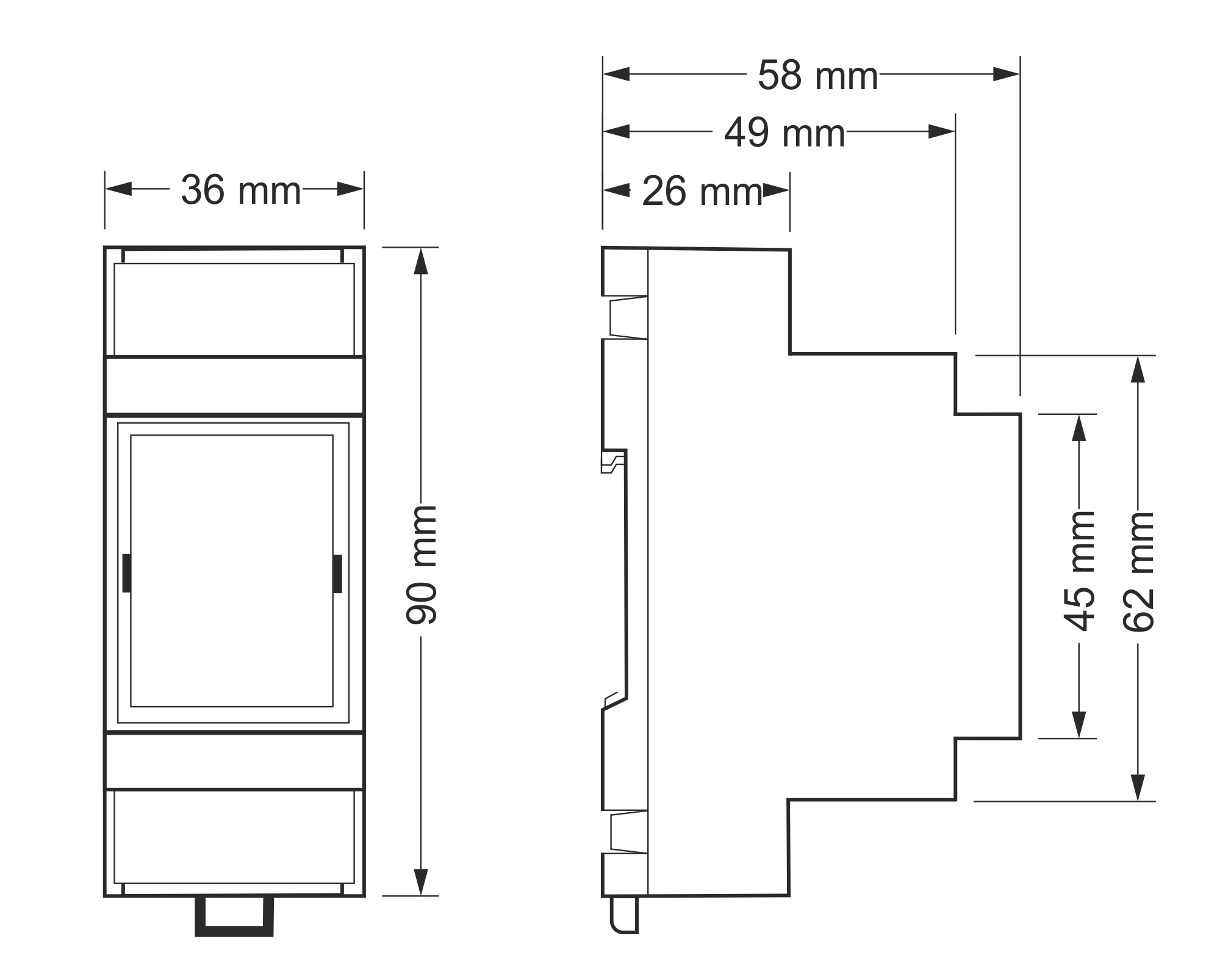
| Overall dimensions (L × W × H) | 36 × 90 × 58 mm |
| Weight (including box) | 135 g |
Operating principle
Indicators
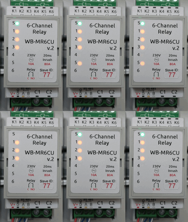
The module has indicators that show its status without connecting to a controller:
- S (green) indicates Modbus communication. It lights when low-voltage power is present and flashes during RS-485 polling. With Fast Modbus events enabled it flashes more frequently. It flashes once per second in bootloader mode and rapidly during firmware upload.
- 1–6 (orange) — output state: lit when the relay contacts are closed.
Outputs
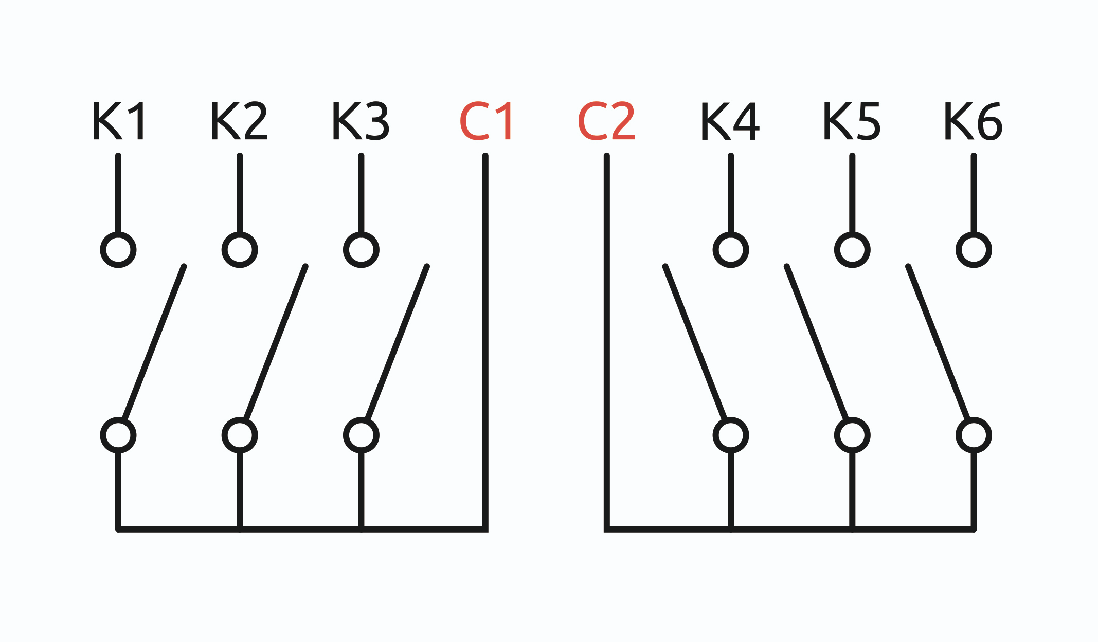
The module contains six HF32FV-16/5-HLTF(590) relays with normally open contacts. The outputs are divided into two groups, each with its own common terminal, COM1 or COM2. Select loads and protective devices according to the permissible switching capacity and load type.
Safety Mode
Safety Mode can stop a process if control over the module is lost, for example if the RS-485 cable is severed. Account for loss of controller communication when designing control systems; see Safety Mode configuration.
Actuator Control
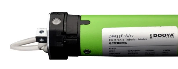
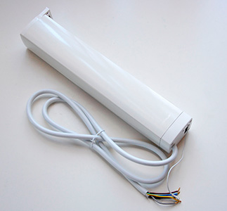
Despite the wide range of digitally controlled actuators, mains-switched actuators remain common for curtains, blinds, shutters, projector screens, air dampers, ball valves and similar devices. Their main control requirement is to prevent simultaneous activation of Open and Close.
The module's Actuator Control combines two relays into one control and uses a software interlock to prevent both relays being energised simultaneously. It also inserts a 500 ms delay when reversing direction and energises the relays for the configured duration (10 seconds by default).
For actuator safety, relay coil commands are ignored in this mode. These outputs can be controlled only through Actuator Control registers.
Actuator Control is disabled by default. Enable it in the settings before use; delays are configured there too.
Delays
Startup Delay When Power On (s) starts when the device firmware boots, approximately 2.5 s after low-voltage power is applied. It switches outputs on sequentially to protect supply circuits from combined inrush currents.
Restart Delay After Output Turn Off (s) starts when the relay switches off. It protects loads sensitive to frequent switching, such as compressors and pumps.
Delays are configured separately for each relay output.
Output timer functions
Timer functions switch module outputs on or off according to a defined timing sequence.
Direct control and timer functions can be used in the same module. Each output can have only one timer function. Outputs are configured independently; changing one output does not affect the others.
Each relay output supports these timer functions: On Delay, Off Delay, Switch on for a time, Switch on for a time (with command reset), Switch off for a time, Switch off for a time (with command reset), On/Off Cycle.
Configure output timers in the device settings.
Installation
Mount the device on a standard 35 mm DIN rail. The V+ GND A B terminal block, with a 3.5 mm pitch, connects the power supply and RS-485 bus. Use a correctly terminated RS-485 bus topology for reliable communication.
If devices on the RS-485 bus use different power supplies, interconnect their GND terminals.
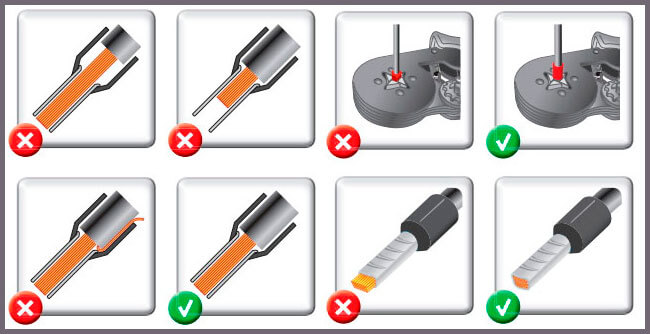
Use flexible stranded wire with insulated wire-end ferrules (NSHVI).
Strip the insulation to the sleeve length, or strip a little more and trim the protruding wire after crimping. Use a ferrule crimping tool. A crimped ferrule protects the strands from the screw clamp and secures the connection.
Do not overtighten the terminal screws: excessive force damages the screw terminal.
Relay switching briefly increases power consumption; choose a supply with adequate reserve. For long supply cables, allow for voltage drop.
Digital inputs activate when connected to iGND. The current is low (~2 mA), so any suitable button or switch type can be used. Cable length and cross-section are not critical for contact detection. To reduce interference from nearby power wiring, use twisted pair and connect iGND to the second conductor of the pair. More about connecting iGND/GND terminals.
The wire cross-section at relay output screw terminals must suit the switched load. The screw terminals accept wire cross-sections of 2.5–4 mm2.
Install the relay module in accordance with electrical safety requirements and prevent accidental contact with live high-voltage terminals. Operate it under the specified environmental conditions.
Installation example
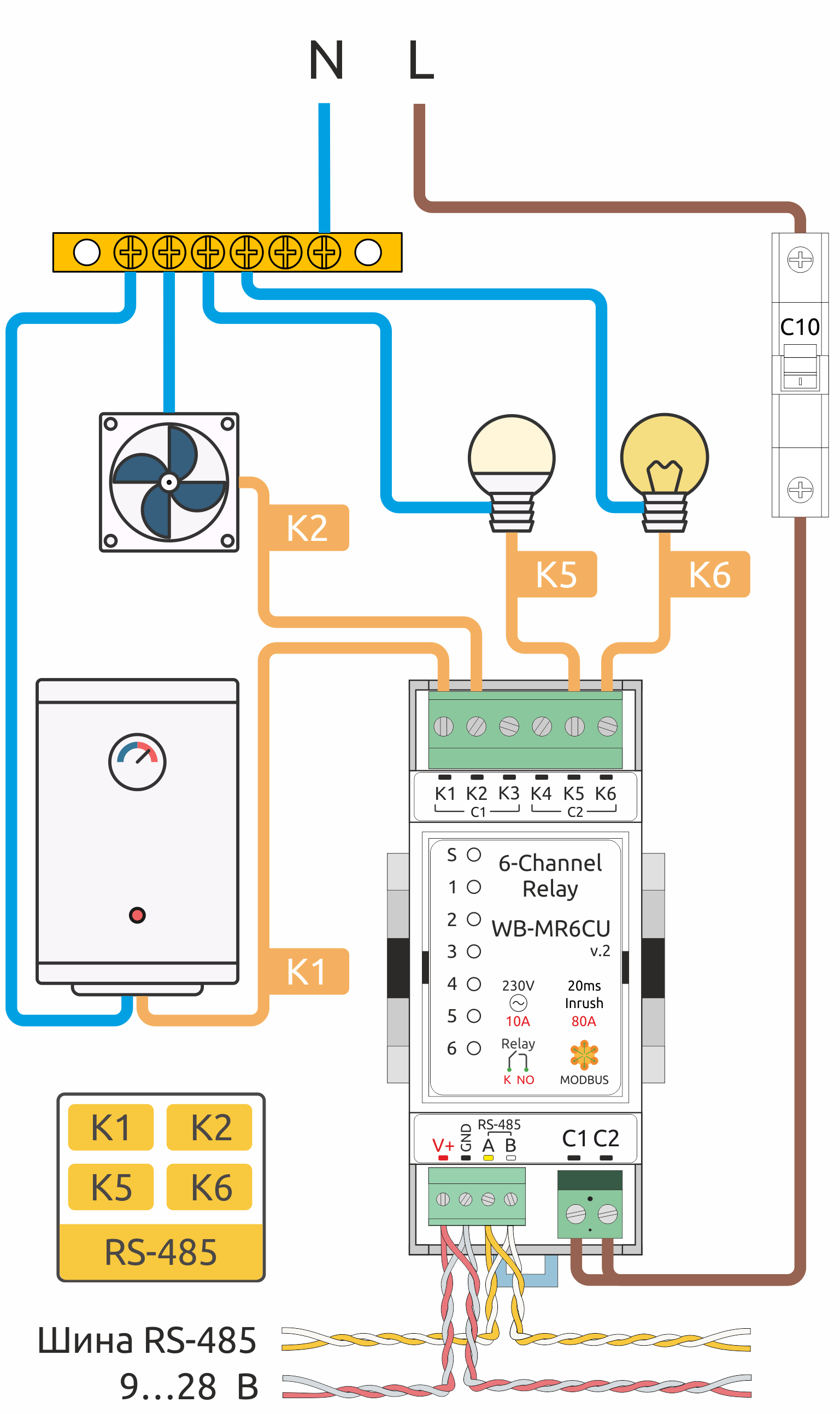
The diagram shows load connections to WB-MR6CU.
In this example, wiring before and after the relay module is protected by a 10 A circuit breaker. Select its rating for the installed conductor size and the module's maximum switching current.
The diagram connects a water heater, a fan, an LED lamp and an incandescent lamp to outputs K1, K2, K5 and K6. The outputs are controlled over RS-485.
Connecting curtain actuators
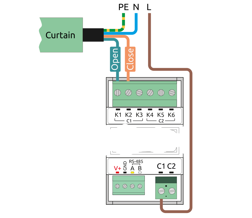
Before connecting a curtain actuator, enable Actuator Control for the outputs used! Incorrect configuration can energise both relays simultaneously and may damage some actuators.
A curtain actuator uses two relays, typically connected to mains phase L and the actuator's Open and Close wires. The actuator is also connected to neutral N and protective earth PE. Always check the proposed wiring against the actuator documentation.
Up to three curtain actuators can be connected to one WB-MR6CU v.2.
| Actuator | Outputs |
|---|---|
| 1 | K1 — open; K2 — close |
| 2 | K3 — open; K4 — close |
| 3 | K5 — open; K6 — close |
Configuration
Configuration methods
- Set the parameters in the Wiren Board controller web interface under Settings → Configs → Serial devices driver configuration. If these menu items are unavailable, check the current access level.
- Write settings to the module's Modbus registers from the controller console with modbus-utils-rpc or modbus_client.
- Without a Wiren Board controller, use the Wiren Board device web configurator or compatible Modbus software on a computer with a USB-to-RS-485 adapter.
Our devices are continually improved. If settings described in this manual are missing, update the device firmware and controller software.
Output states at power-on
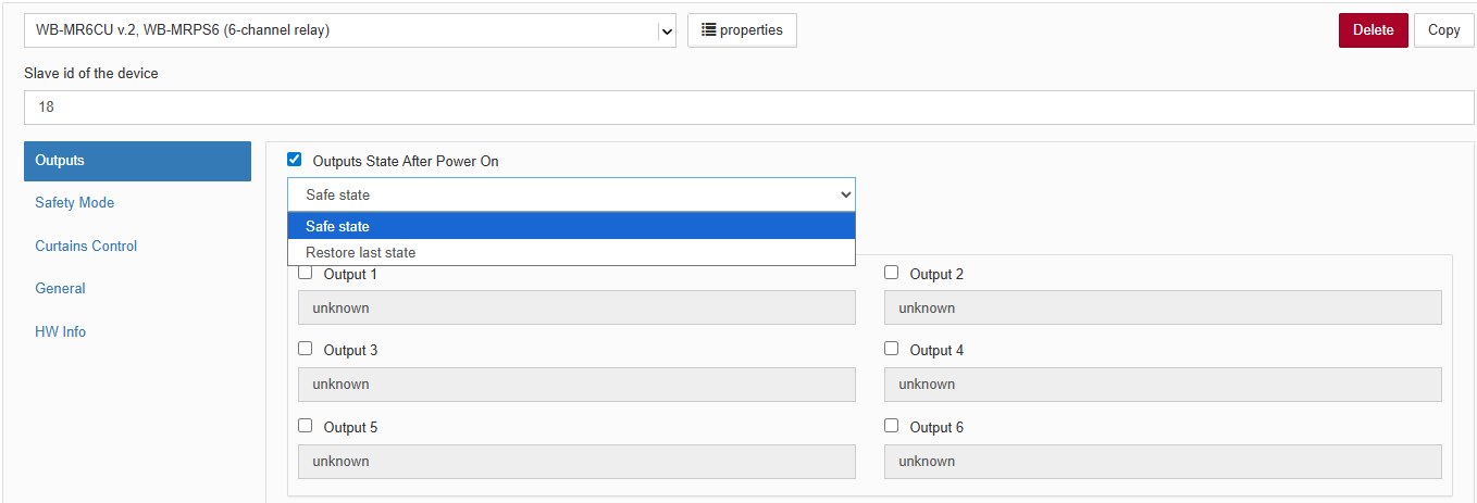
The following power-on behaviours are available:
- Safe state (default) — after power-on, outputs follow the setting Output Safe State;
- Restore last state — saves the last output state and restores it when power returns.
Safety Mode
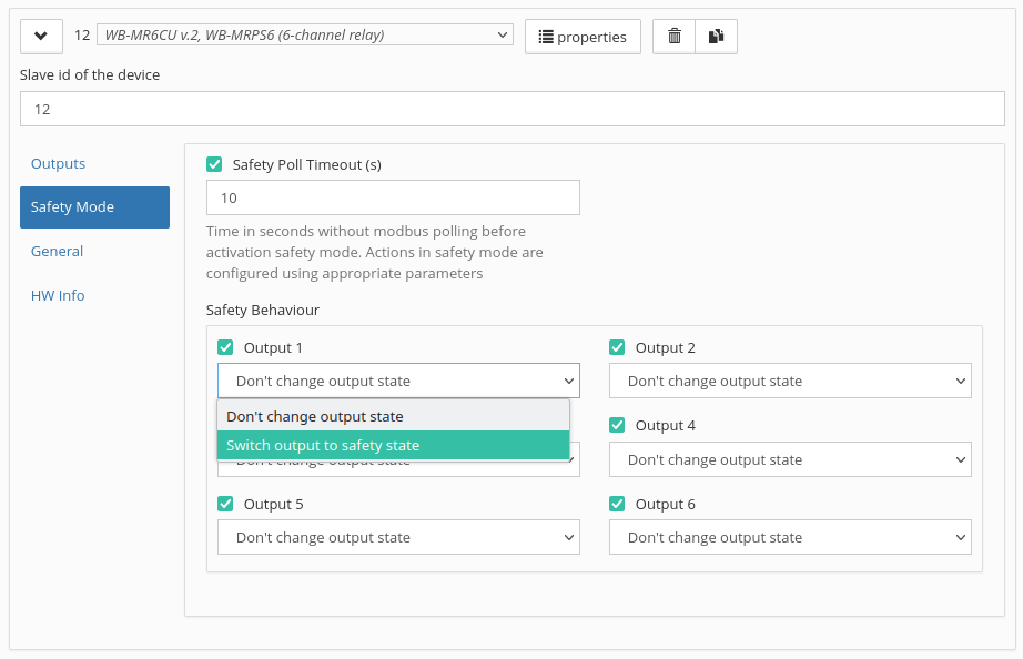
Safety Mode can stop a process if control of the module is lost, for example because the RS-485 cable is severed. Account for communication loss when designing control systems.
The fail-safe timer restarts after every successfully processed Modbus packet. When the configured interval expires, the relay enters Safety Mode; normal operation resumes when communication returns. The default value is 0, which disables Safety Mode.
Actuator Control
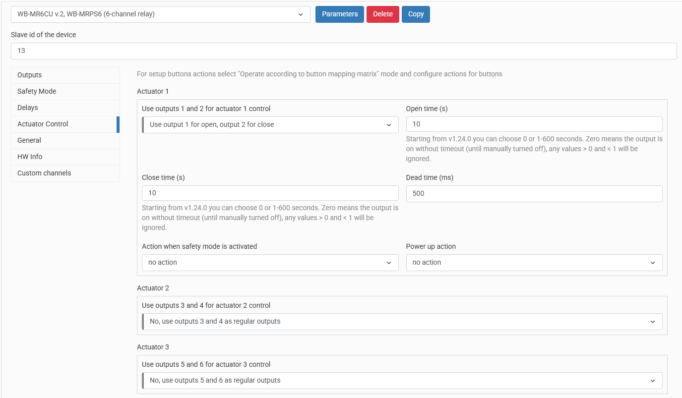
To use an actuator, select the corresponding output mode on the Actuator Control tab. Opening/closing times, direction-change pause, power-on actions and safe-mode actions then become available.
Outputs in one module can use different modes: for example, K1 and K2 can control an actuator while K3–K6 operate normally.
Configuring protective delays
In the device settings, open Protective Functions and set the Startup Delay When Power On (s) or Restart Delay After Output Turn Off (s) for the corresponding relay output.
Configuring output timers
In the device settings, open Timers, select a function and configure its duration for the corresponding relay output.
- Protective delay and timer configuration examples
-
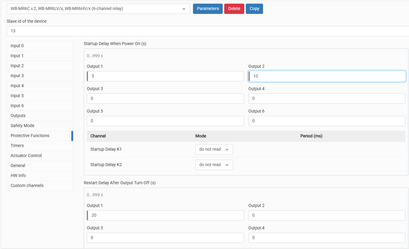 Configuring protective delays in the Wiren Board controller web interface
-
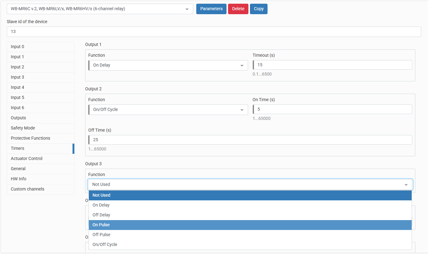 Configuring relay timers in the Wiren Board controller web interface
Wiren Board controller web interface
Selecting a template
To display the device on the Devices in the Wiren Board controller web interface, add it automatically through RS-485 device discovery or manually by selecting the template:
- current software release — WB-MR6CU v.2, WB-MRPS6,
- older software versions — WB-MR6CU.
Controlling the device and viewing values
The web interface lets you control the outputs and view device values. Choose the displayed channels in the wb-mqtt-serial device settings.
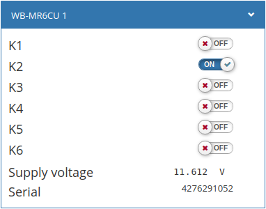
Use the K1–K6 virtual switches in the web interface to control the corresponding WB-MR6CU outputs and monitor their state.
The panel also displays the WB-MR6CU supply voltage and serial number.
Modbus operation
Wiren Board devices use Modbus RTU over the physical RS-485 interface.
All main Modbus commands for reading and writing one or multiple registers are supported.
The module can be configured:
- in the Wiren Board controller web interface;
- with the Wiren Board device web configurator;
- with third-party software.
Default port settings
| Value default |
Parameter name in the web interface |
Parameter |
|---|---|---|
| 9600 | Baud rate | Baud rate, bit/s |
| 8 | Data bits | Number of data bits |
| None | Parity | Parity |
| 2 | Stop bits | Number of stop bits |
In current firmware, setting Stop bits is optional: the device also operates correctly when its number of stop bits differs from the Modbus master setting.
For a faster response, we recommend increasing the baud rate to 115200 bit/s; configure the same communication parameters on the Modbus master
Modbus address
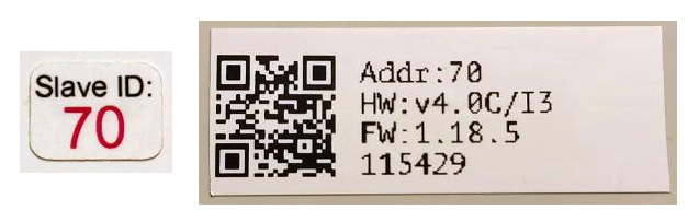
Each device on the bus must have a unique address from 1 to 247. The factory-assigned address is printed on labels on the enclosure (top cover, side or underside). Devices in a production batch are assigned different addresses, so devices in one order will usually have different addresses.
The address can be discovered, changed or reset with Wiren Board controller tools or compatible Modbus configuration software.
Fast Modbus extension
Fast Modbus extends standard Modbus with rapid discovery of Wiren Board devices on RS-485 and event polling.
These features are enabled by a special command from the master, so Wiren Board devices remain compatible with third-party equipment.
Not every register supports event generation. Check the register map: event-capable registers are marked with ⚡. See Fast Modbus.
Register map
Relay module register map
Firmware updates and resetting settings
Wiren Board devices support firmware updates over Modbus. This allows bugs to be fixed at the installation site and, where technically possible, new features to be added. Settings stored in the device are retained during a firmware update.
Instructions:
- Firmware update (video tutorial)
- Resetting settings
- Connection parameter settings
- Modbus address: find, reset or change
- Updating the bootloader
New firmware releases are listed in the device firmware changelog.
Known issues
Known issues
Hardware revisions
Revision history
Troubleshooting
Interference from relays and contactors
Relays and contactors can interfere with nearby devices. When switching loads, especially inductive loads, the contacts generate high-frequency transients with amplitudes of several kilovolts that may couple into other circuits. Snubber circuits suppress these transients, reducing interference and improving equipment stability.
Device images and drawings