 Documentation
Configuration with WB-MGE v.3
Read the complete WB-MGE v.3 manual, including current port modes, specifications and service instructions.
Configuration instructions for the WB-MGE v.3 gateway, including its network interfaces, RS-485 ports and built-in WB-MIO interface for WBIO side modules.
I/O Bus: WBIO side modules
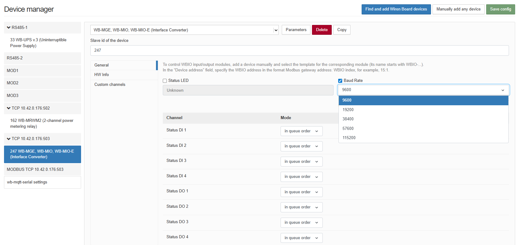
Side modules operate through a built-in WB-MIO, presented as a Modbus device on RS485-2. Its defaults are Modbus address 247 and 9600 bit/s, 8 data bits, no parity, 2 stop bits (8N2).
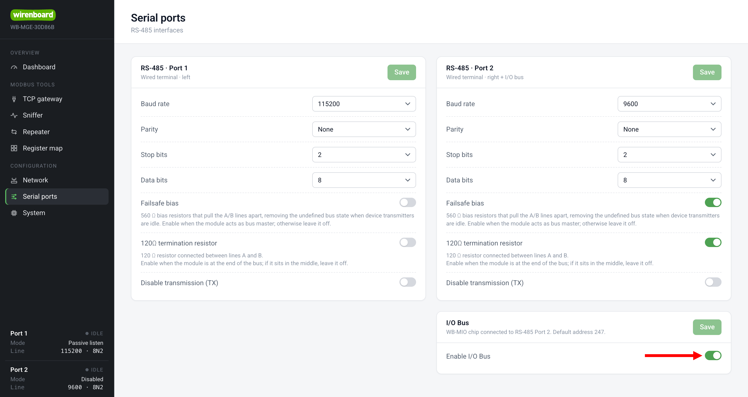
To enable or disable it, open Configuration → Serial ports, find the I/O Bus card and change Enable I/O Bus. WB-MIO is enabled by default. Disable it if you need to release its Modbus address or use a protocol on RS485-2 that conflicts with Modbus RTU.
The communication settings of devices connected to RS485-2 and the built-in WB-MIO must match. If they differ, change the WB-MIO settings by writing new register values. You can do this through wb-mqtt-serial in the controller web interface, with modbus_client over SSH while RS485-2 is in Modbus TCP mode, or by connecting directly to RS485-2 through a WB-USB485 converter.
Example: stop the controller driver, set the WB-MIO baud rate, then restart the driver:
systemctl stop wb-mqtt-serial
modbus_client --debug -mtcp -a247 -c1 -r110 -t0x06 -o300 -p503 10.42.0.176 1152
systemctl start wb-mqtt-serial
Here, 247 is the WB-MIO address and 10.42.0.176 is the gateway IP address. Register 110 uses a ×100 multiplier: 1152 means 115,200 bit/s.
WB-MIO communication registers
All registers below are holding registers, readable and writable (RW), with unsigned 16-bit values (u16).
| Decimal | Hex | Parameter | Values |
|---|---|---|---|
| 110 | 0x006E | RS-485 baud rate | ×100 baud: 12 = 1,200; 24 = 2,400; 48 = 4,800; 96 = 9,600; 192 = 19,200; 384 = 38,400; 576 = 57,600; 1152 = 115,200 bit/s |
| 111 | 0x006F | Parity | 0 = none; 1 = odd; 2 = even |
| 112 | 0x0070 | Stop bits | 1 or 2 |
| 128 | 0x0080 | Device Modbus address | Modbus slave address |
Network configuration
The module can connect through Ethernet and Wi-Fi independently, or use both simultaneously—for example, Wi-Fi access-point mode for initial setup and Ethernet for normal operation.
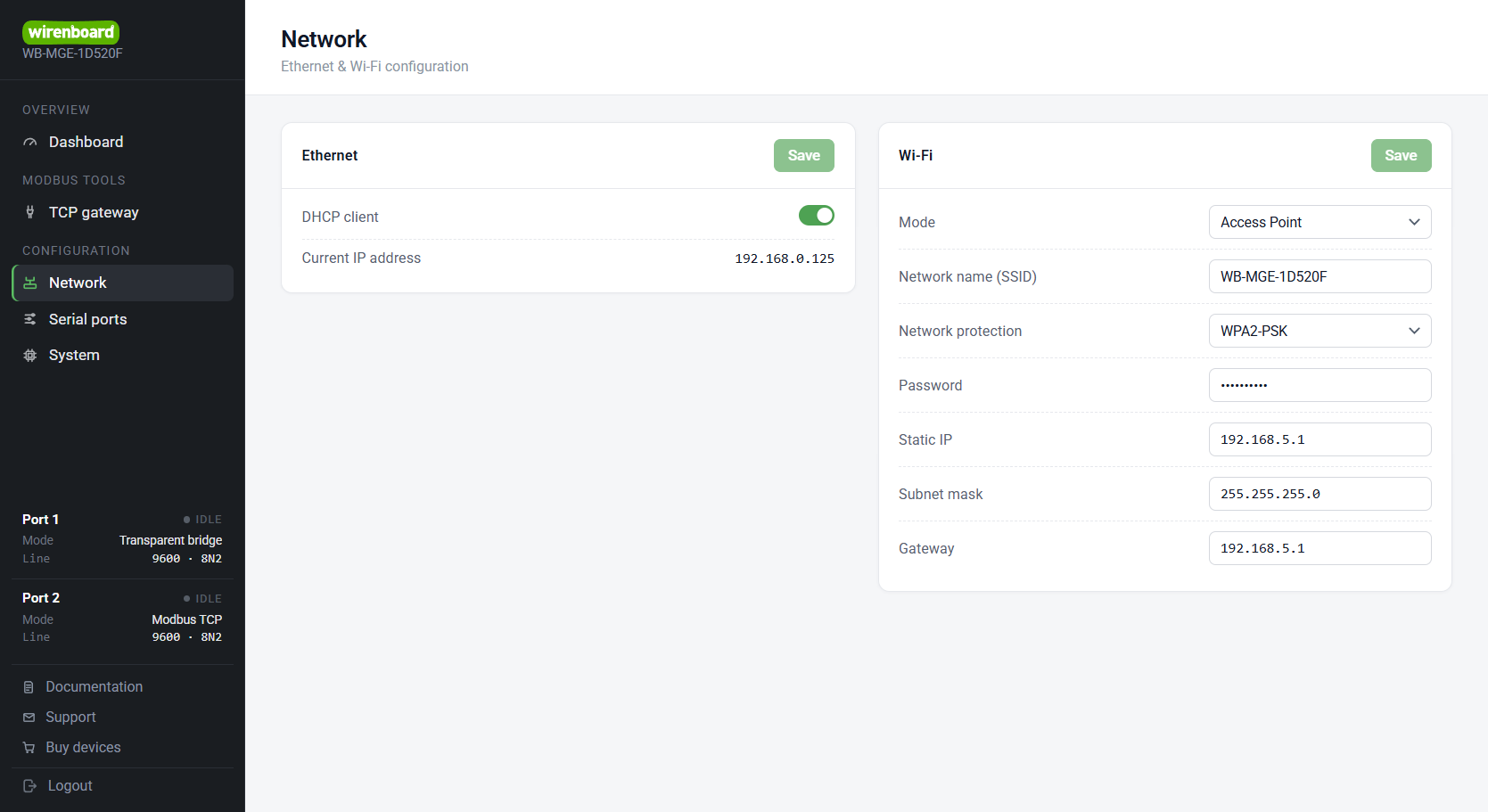
Under Configuration → Network → Ethernet, the DHCP client is enabled by default, so the router assigns the IP address. To use a static address, disable the DHCP client and enter the IP address, subnet mask and gateway manually.
Under Configuration → Network → Wi-Fi, select one of these modes:
- Access point (AP): the default. The module creates a network named
WB-MGE-XXXXXX. Configure its SSID, password, authentication type and IP address, mask and gateway. - Client (station): joins an existing Wi-Fi network. Enter that network's SSID and password, then select DHCP or enter a static address, mask and gateway.
- Disabled: completely disables the Wi-Fi interface. A separate permanent-disable option is described below.
The current firmware has no DNS-server setting. The module works on the local network using IP addresses without resolving external domain names.
Quick start
This sequence covers one WB-MGE v.3, RS-485 devices (including Fast Modbus devices), and a controller on the same network.
- Connect the power supply and RS-485 A/B/GND terminals. Leave termination enabled if the gateway is at the end of the bus; disable it if the gateway is in the middle.
- For initial access, join the module's
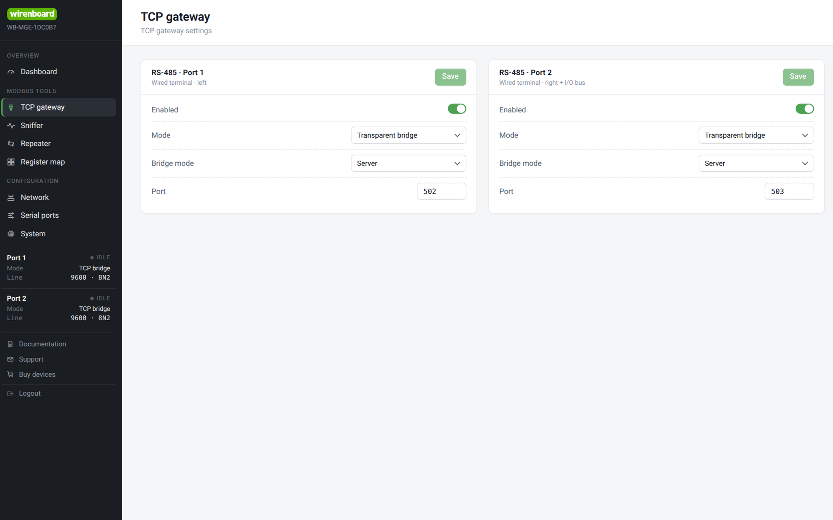
WB-MGE-XXXXXXWi-Fi network using the password on its side label. Open192.168.5.1and sign in with the default credentialsadmin / admin. For normal operation, connect the module and controller to the same network. - Go to Modbus tools → TCP gateway, select the RS-485 port card and set Mode to Modbus TCP. The default TCP ports are 502 for RS-485-1 and 503 for RS-485-2.
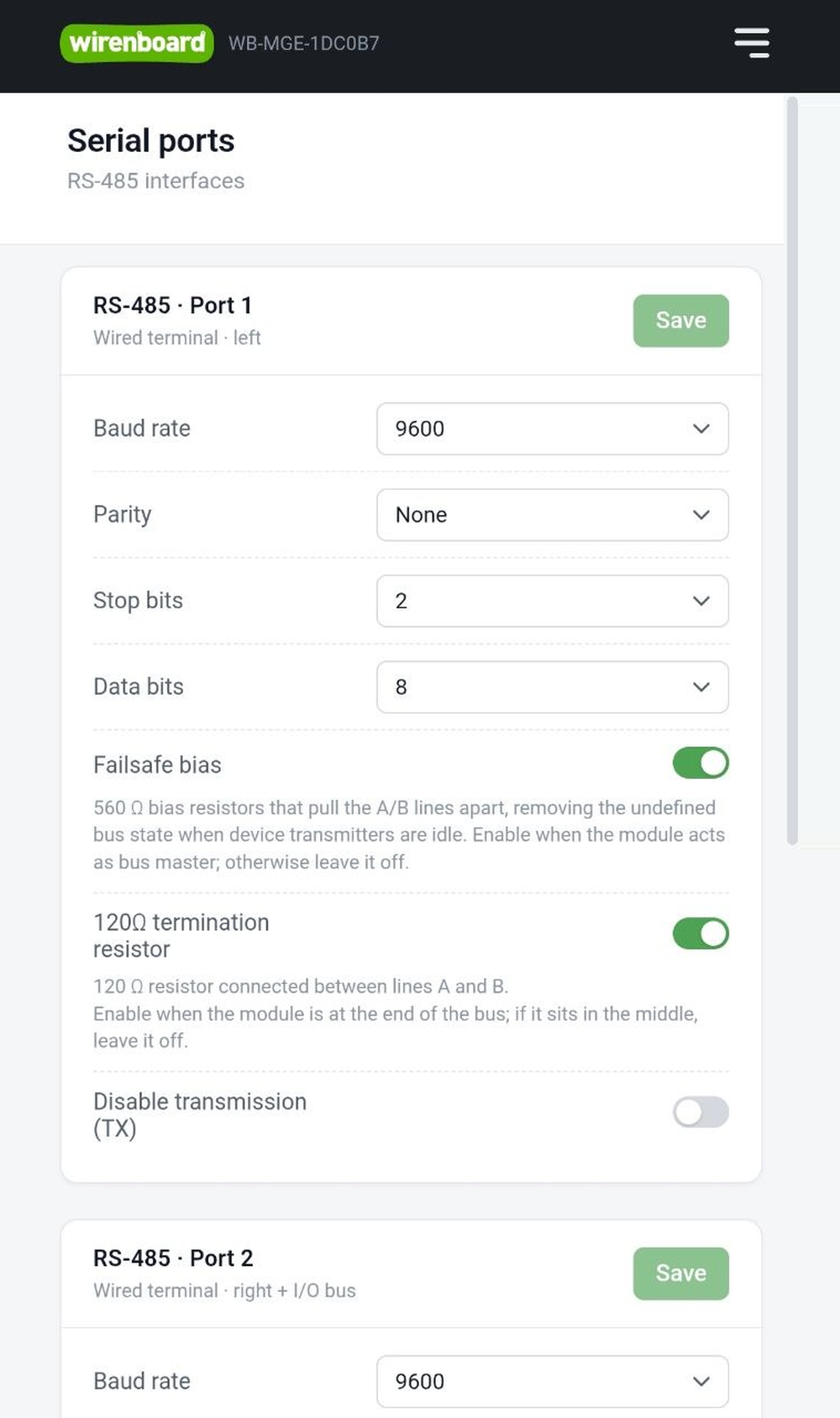
- Under Configuration → Serial ports, enable termination only at a bus end, and enable failsafe bias only when the module is the master on that bus. Incorrect settings commonly cause devices to stop responding without an explicit error.
- Find the module's IP address under Configuration → Network.
- In the controller's
wb-mqtt-serialsettings, add a Modbus TCP port. Enter the gateway IP address and the TCP port selected above. Keep the default timing settings for a local network. Add devices through automatic discovery, or manually with their slave IDs and device templates. - Check that device values appear in the controller web interface and in MQTT under
/devices/.../controls/.... If they do not, check TCP-port matching, termination and failsafe bias.
Web interface
The gateway web interface works in modern desktop and mobile browsers. Connect the computer and module to the same network through Wi-Fi or Ethernet. Wi-Fi access-point mode assigns IP addresses to clients automatically. Ethernet obtains an address through DHCP, for example from your router. Network details are also available in the debug console through the USB-C connector beneath the cover.
| Setting | Default |
|---|---|
| Login / password | admin / admin |
| mDNS hostname | wb-mge-XXXXXX.local; alternatively, append .local to the access-point name printed on the label |
| Wi-Fi access point | WB-MGE-XXXXXX, using the Ethernet MAC-address suffix printed on the label |
| Wi-Fi key | Printed on the side label |
| Wi-Fi IP address | 192.168.5.1 |
| Wi-Fi subnet mask | 255.255.255.0 |
| Ethernet IP address and subnet mask | DHCP |
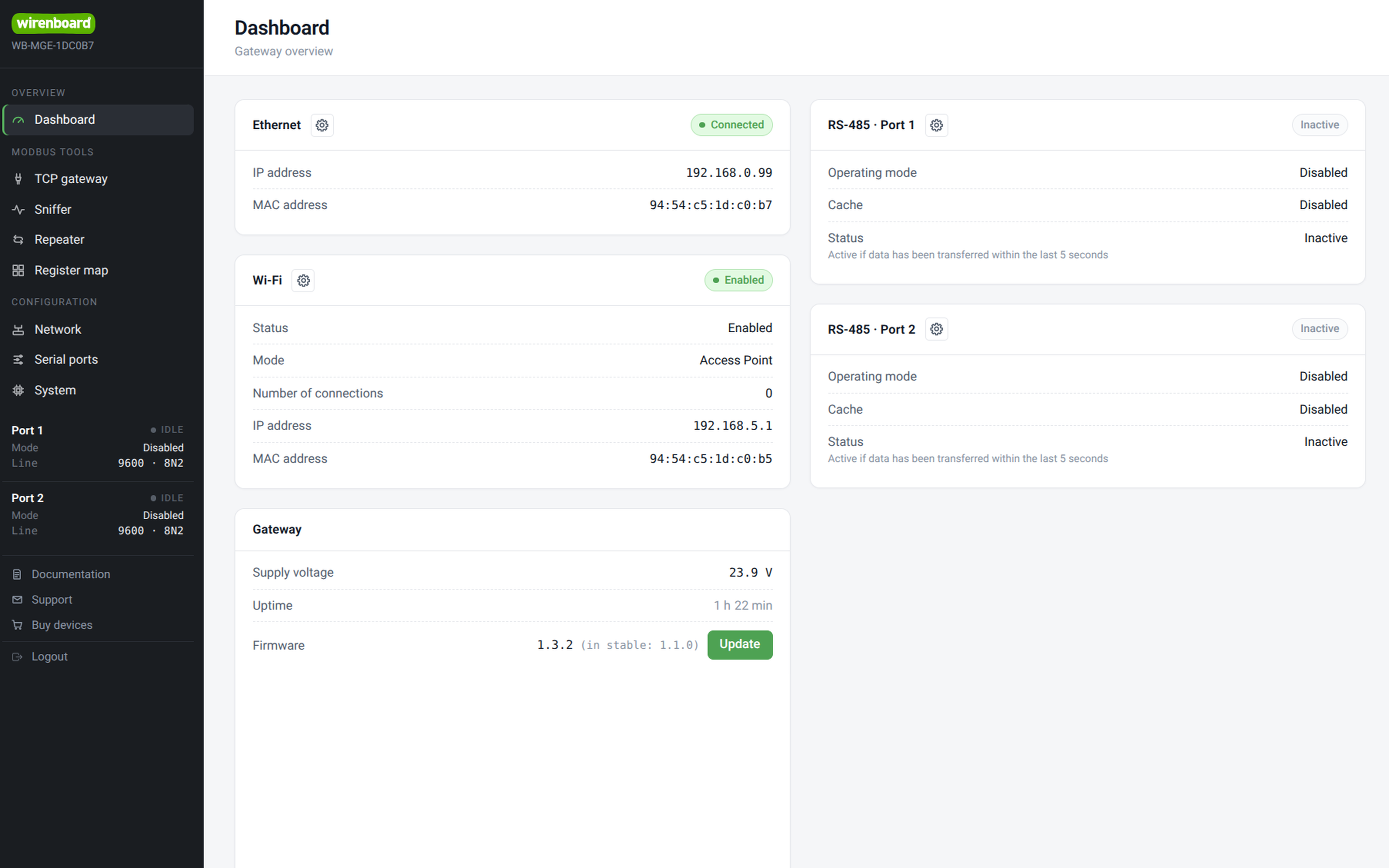
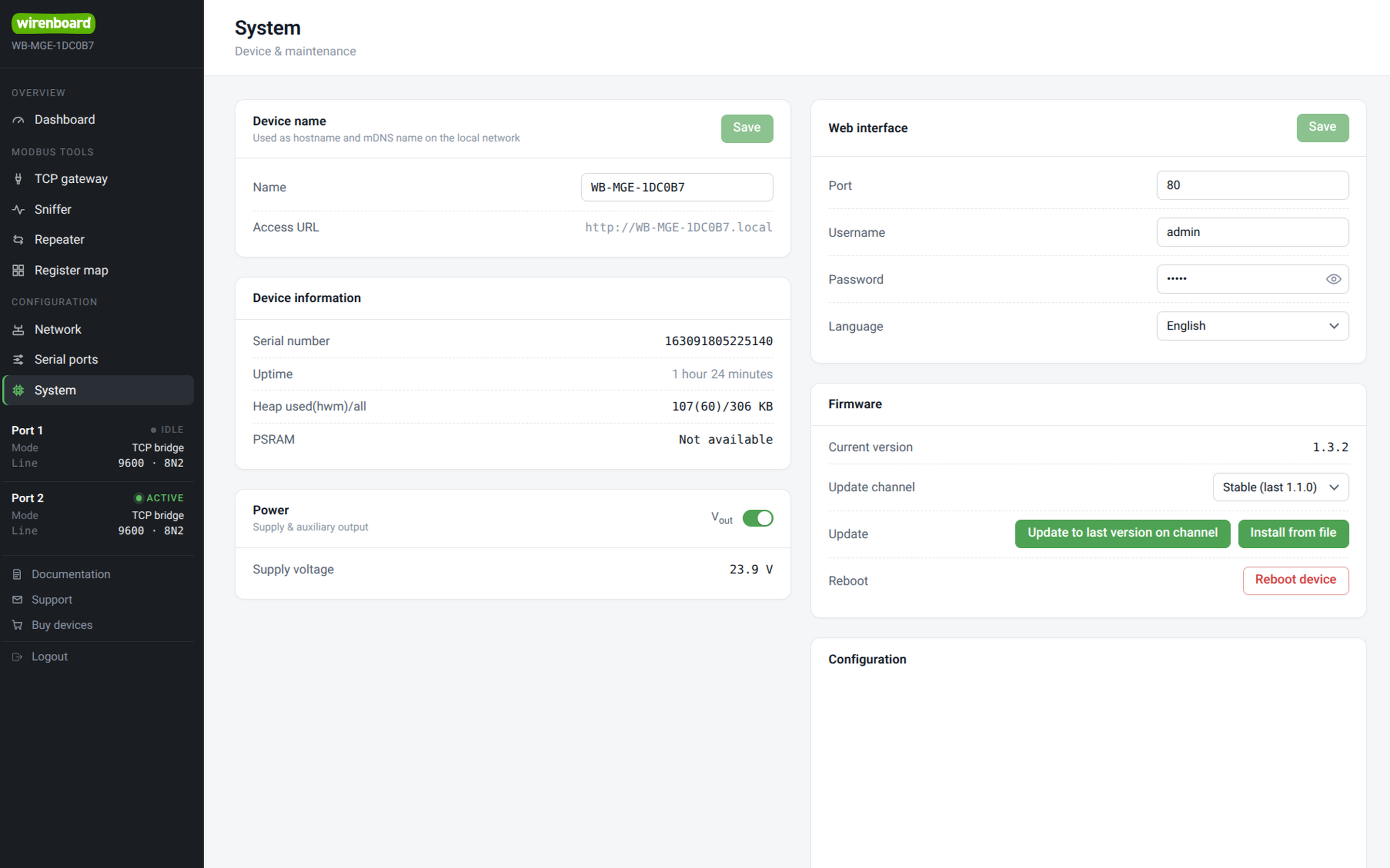
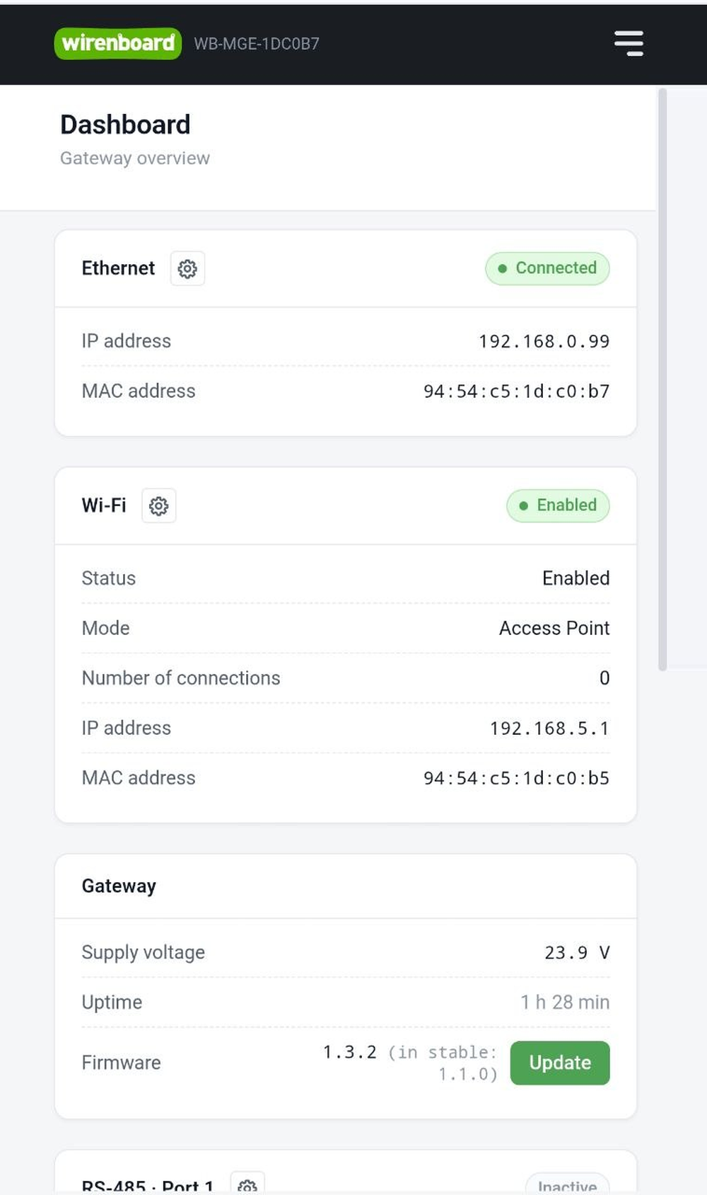
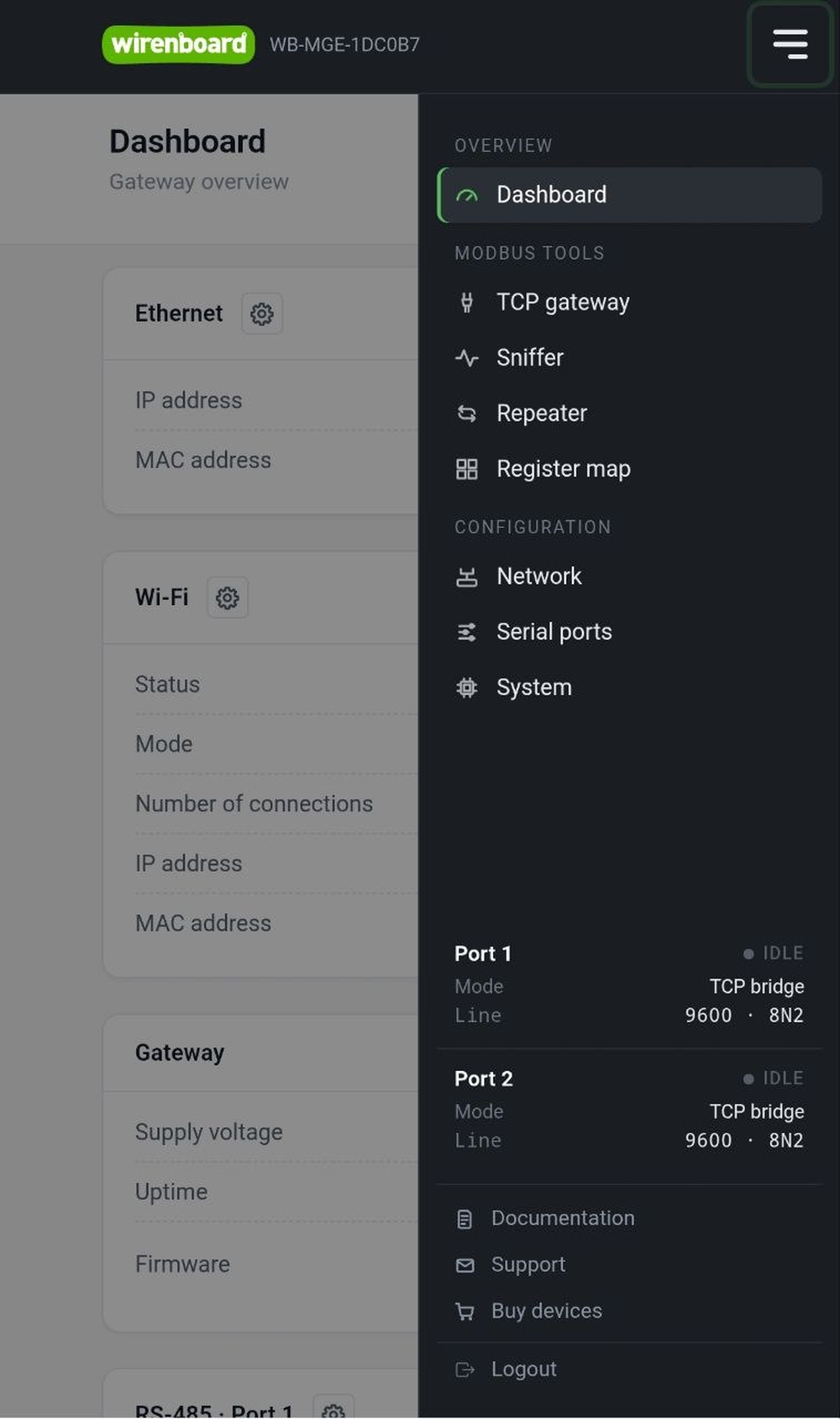
Access through the Wi-Fi access point
- Find
WB-MGE-XXXXXXin the Wi-Fi network list on your laptop or phone. - Enter the security key printed on the device's side label.
- Open
192.168.5.1; the default login and password areadmin / admin.
Access through Ethernet
Ethernet uses DHCP by default, so a router providing DHCP is required—typically a home or office router.
- Connect the gateway to the router with an Ethernet cable.
- Open the router settings and find the IP address assigned to the gateway.
- From a computer connected to the same router, open that address in a browser and sign in with
admin / admin.
Access through a controller Ethernet port
If the module is on a different subnet behind the controller, use an SSH tunnel. In this example the controller is 192.168.42.1 and the module is 192.168.0.7.
On Linux/macOS with OpenSSH, or Windows PowerShell/CMD:
ssh -N -L 8088:192.168.0.7:80 root@192.168.42.1Enter the controller's password when prompted; its default is wirenboard. The -L option forwards local port 8088 to 192.168.0.7:80 through the controller; -N prevents a remote command from being started. If port 8088 is occupied, choose another free local port. Keep the SSH session open while using the web interface.
With PuTTY on Windows:
- Set Session → Host Name to
192.168.42.1. - Open Connection → SSH → Tunnels.
- Set Source port to
8088and Destination to192.168.0.7:80. - Select Local, then click Add.
- Return to Session, click Open and log in as
root.
Open http://127.0.0.1:8088/ in a browser and enter the gateway's login and password.
Access through Wiren Board Cloud
If WB-MGE v.3 is connected to one of the controller's network interfaces and the controller is connected to Wiren Board Cloud, you can configure proxy access to the gateway web interface through the cloud.
Saving and loading configuration
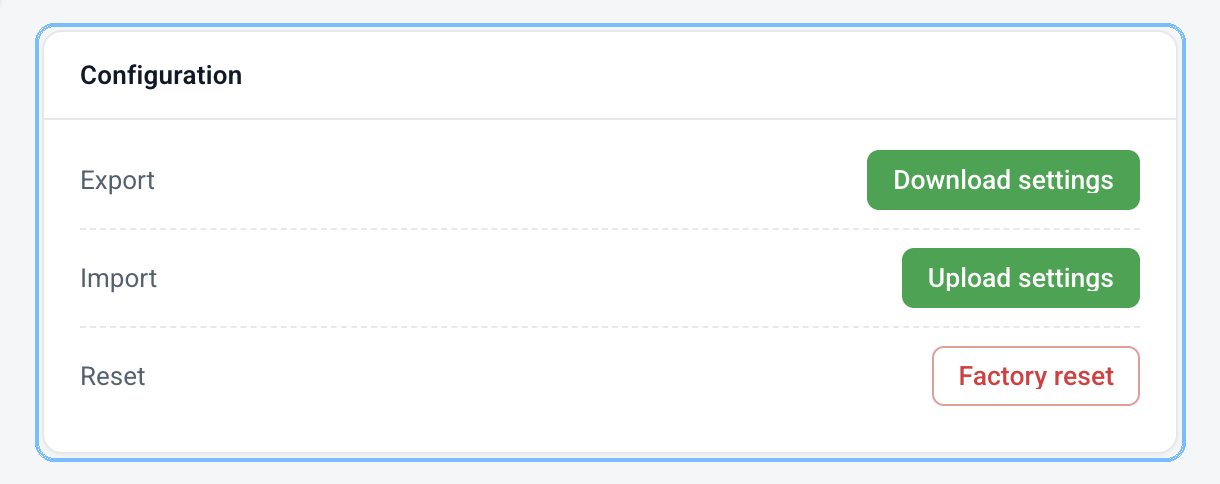
Export the configured parameters to a file for restoration on another device or reuse in similar installations. The file includes all web-interface, port and network-interface settings.
Termination and failsafe bias
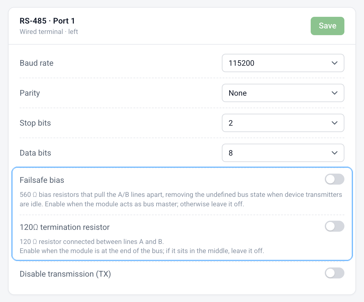
The module has the following resistors, both enabled by default:
- Termination: a 120 Ω resistor between A and B. Enable it at the end of the bus; disable it in the middle.
- Failsafe bias: 560 Ω bias resistors that establish a defined bus state when all transmitters are disabled. Enable them when the module is the master; disable them otherwise.
Control these settings in software under Configuration → Serial ports, on the relevant port card.
Disabling transmission (TX)
Available from firmware version 1.3.0.
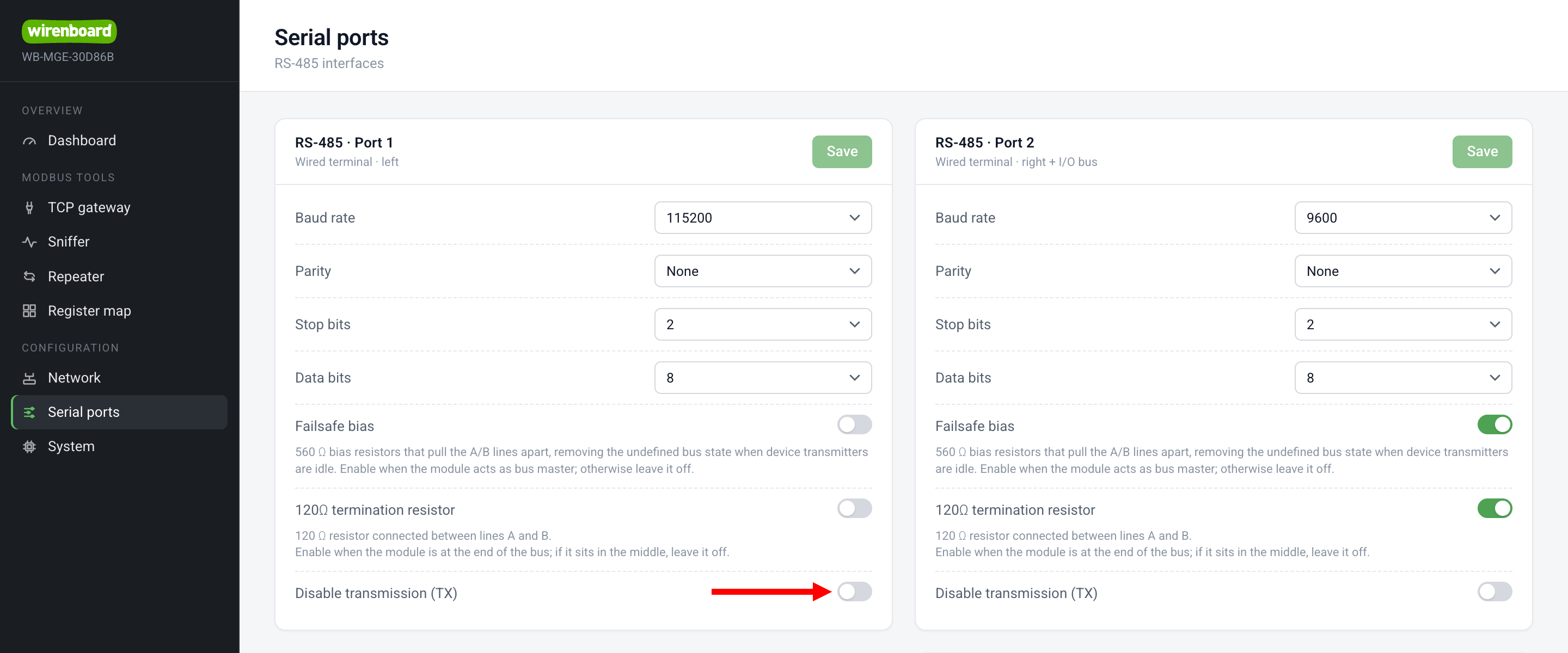
Each RS-485 port has a Disable transmission (TX) switch under Configuration → Serial ports. This physically places the transceiver in receive-only mode: the direction-enable pin (DE) is detached from the UART and held inactive. While enabled, software cannot transmit onto the bus; transmission attempts are silently discarded.
This allows connection to a running installation for traffic analysis or mirroring using the sniffer or caching multimaster without accidental transmission disrupting the system. The sniffer's Send packet button is unavailable for receive-only ports.
Permanently disabling Wi-Fi
Available from firmware version 1.3.0.
In this mode the Wi-Fi driver is no longer initialized. The radio stays off on subsequent boots and the Wi-Fi settings disappear from the web interface. The mode cannot be reversed through the API.
Activate it through the API, then reboot:
# Authenticate
curl -s -c cookies.txt -X POST http://192.168.0.7/auth -H 'Content-Type: application/json' -d '{"login":"admin","pass":"admin"}'

# Permanently disable Wi-Fi
curl -s -b cookies.txt -X POST http://192.168.0.7/settings -H 'Content-Type: application/json' -d '{"wifi_perm_disable": true}'

# Reboot to apply
curl -s -b cookies.txt -X POST http://192.168.0.7/cmd -H 'Content-Type: application/json' -d '{"cmd": "reboot"}'
After reboot, GET /settings omits the wifi group and includes "wifi_perm_disable": true. Sending {"wifi_perm_disable": false} is silently ignored. To restore Wi-Fi, reset the gateway to factory defaults by holding Config for 5 seconds, or reflash the device.
Configuration in the Wiren Board controller
Controller and gateway on the same router, both using DHCP
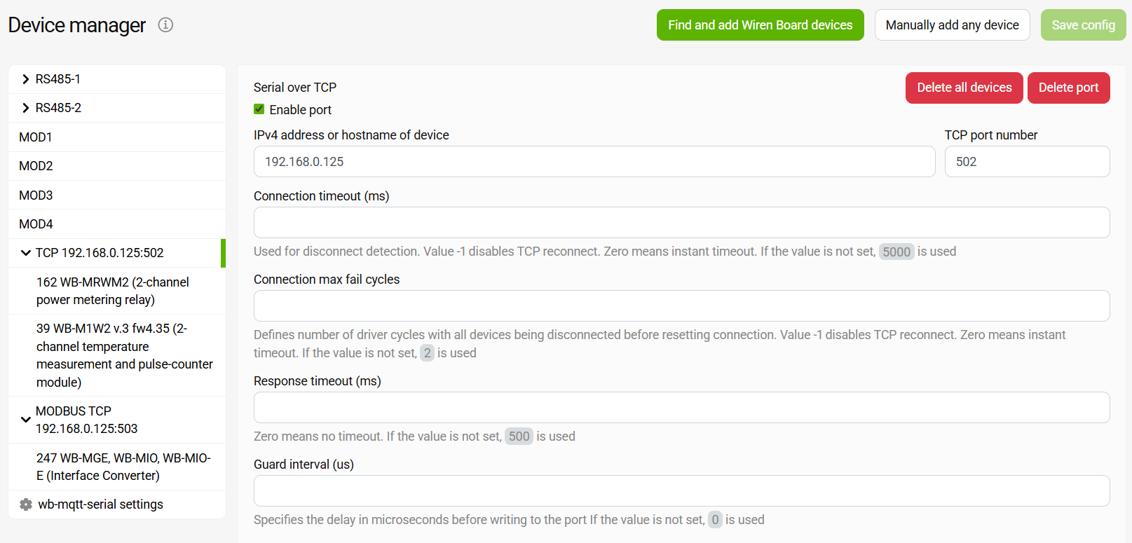
The illustrated gateway receives 192.168.0.125. Use the actual address assigned by your router.
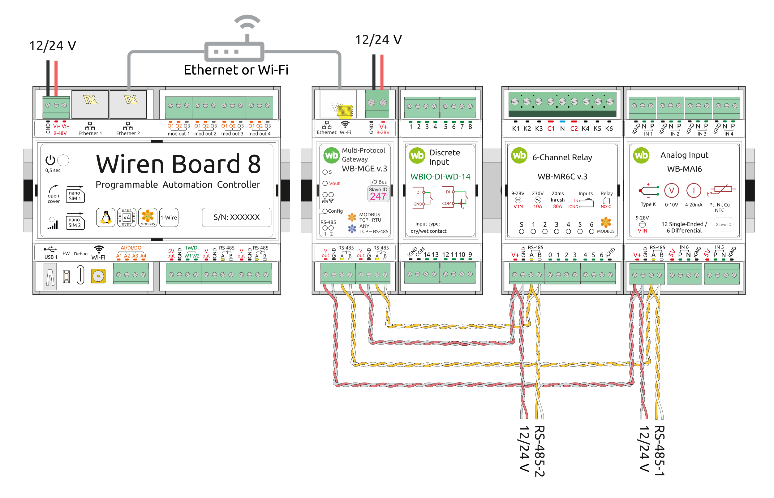
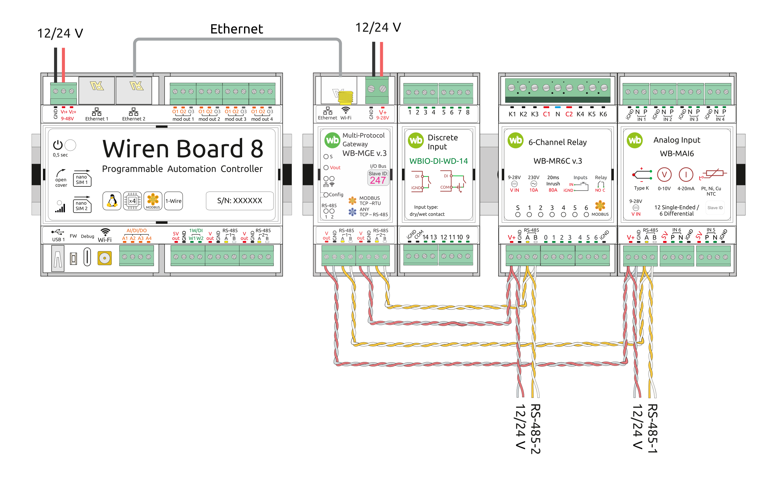
Direct Ethernet connection: controller shares IPv4, gateway uses DHCP
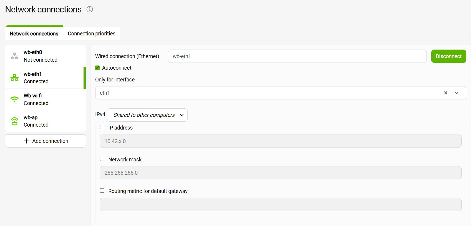
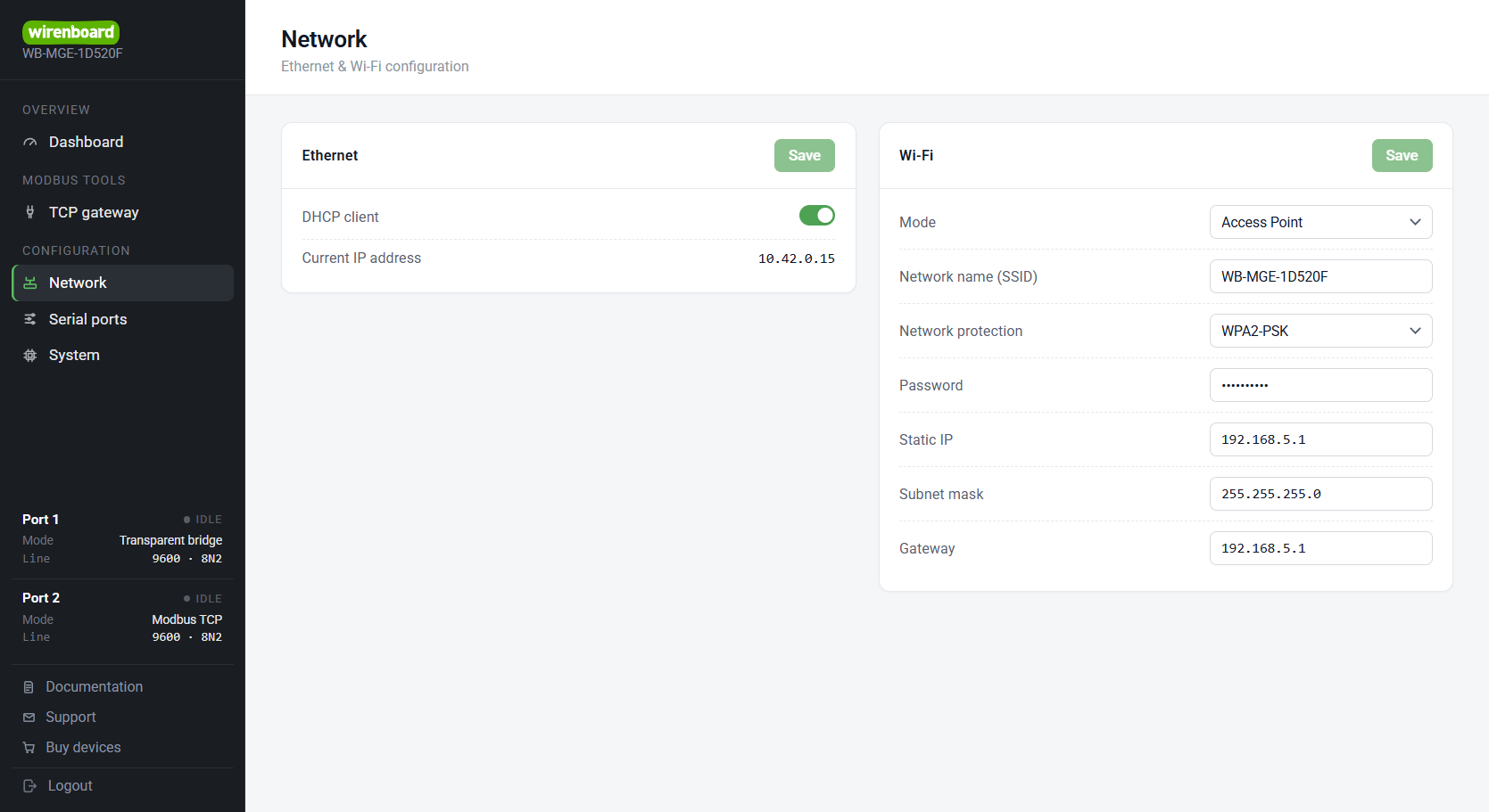
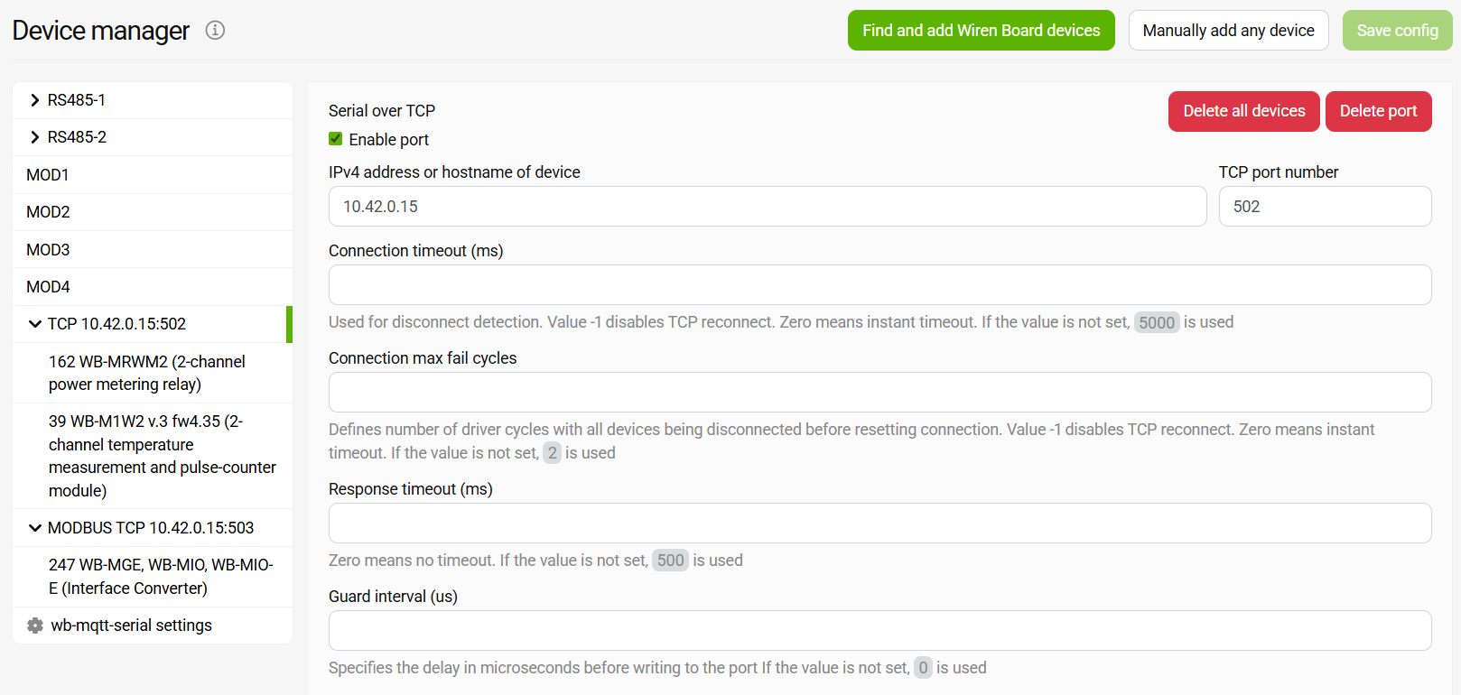
Set the controller Ethernet port to IPv4: Shared to other computers and the gateway to DHCP client. The illustrated gateway receives 10.42.0.15.
Direct Ethernet connection with static addresses
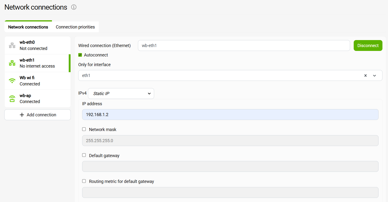
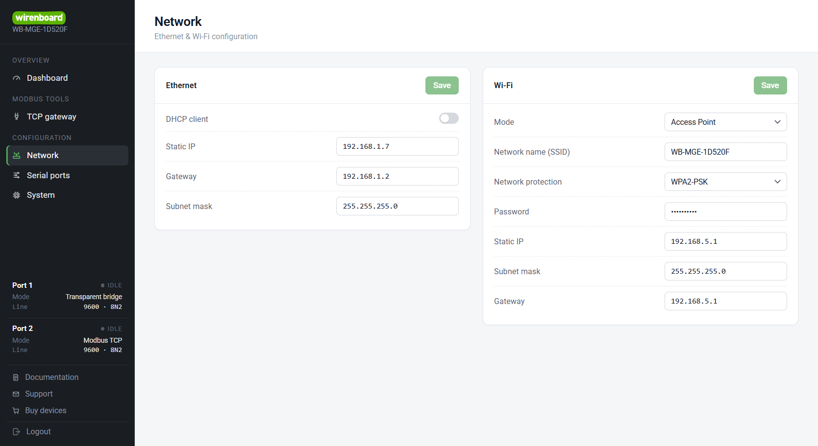
The example uses controller Ethernet 2 at 192.168.1.2 and gateway 192.168.1.7, both with static IP configuration.
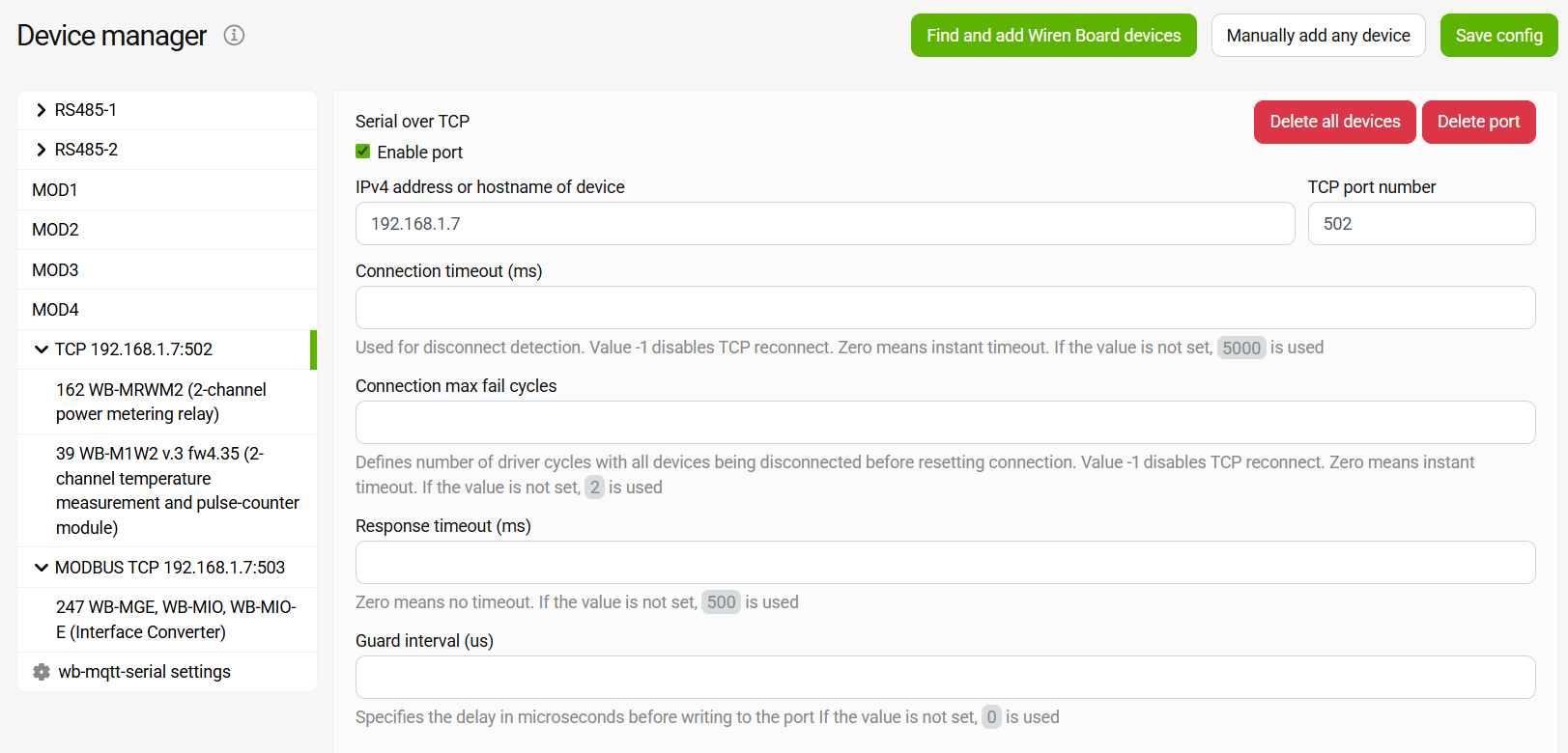
To control Modbus devices connected to the gateway, configure wb-mqtt-serial on the controller:
- Add TCP ports for the gateway's RS-485-1 and RS-485-2 interfaces.
- Add devices using automatic device discovery or manually by selecting their templates. They will then appear on the controller's Devices page.
- Add WBIO side modules manually using their templates. With a Wiren Board controller, the address is
<WB-MIO Modbus address>:<WBIO sequence number, starting at 1>. With the default internal address, the first module is247:1. Third-party controllers or software must calculate addresses using the WB-MIO register map.