Documentation
WB-MAP12E
4-circuit three-phase / 12-channel single-phase power meter
Covered order codes (1)
WB-MAP12E— Meter without current transformers; selectable CT sets are available on the product card
Buy online
Purpose
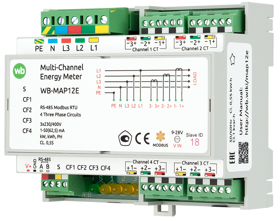
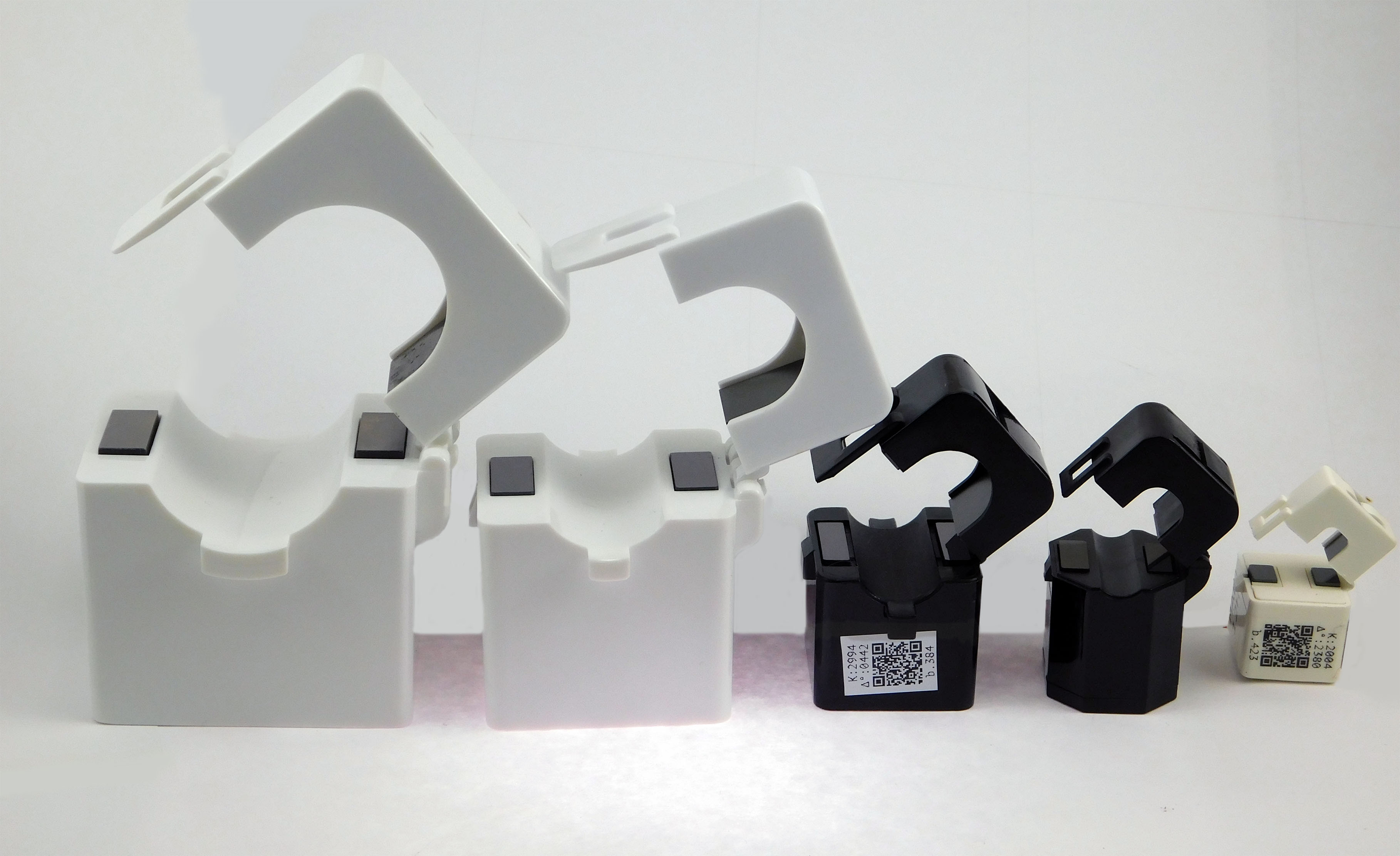
This energy meter and electrical-network analyser is intended for energy management and power-quality monitoring, including operational submetering in apartment and office buildings and load monitoring in data centres and smart offices. External split-core current transformers allow installation around conductors without interrupting the loads. Accuracy class is 0.5S for active energy and 1 for reactive energy.
Unlike WB-MAP12H, WB-MAP12E measures peak current and voltage over defined intervals. WB-MAP12E does not measure current or voltage harmonic amplitudes or total harmonic distortion.
Technical specifications
WB-MAP measures and calculates electrical-network parameters including:
- RMS phase voltages and currents (Urms, Irms);
- peak phase currents and voltages. Detectable peak duration starts at 300 µs and is determined by input filtering. Two sets of registers are available:
- instantaneous peaks — maximum over the detection interval, 20 ms by default;
- aggregated peaks — maximum over the aggregation interval, 60 s by default.
- line-to-line voltages for three-phase loads;
- active, reactive, apparent and non-active power;
- power factor;
- forward and reverse active, reactive, apparent and non-active energy;
- total power and energy for three-phase loads and/or multiple channels;
- phase angle between voltage and current;
- frequency.
RMS and peak currents and voltages, power, power factor, phase angles and frequency are sampled several thousand times per voltage cycle, averaged over 16 cycles and updated in registers every 320 ms. Energy registers are updated as energy is accumulated.
The complete parameter set is described in the WB-MAP measurement reference. The exact set supported by a meter depends on its model.
Accuracy class is 0.5S for active power and energy and 1 for reactive power and energy.
Relative measurement errors depend on the measured value and load type.
WB-MAP meters are registered measuring instruments under Russian State Register number 79082-20; their metrological and technical characteristics are defined in the approved type description.
Technical specifications
| Parameter | Value |
|---|---|
| Power supply | |
| Supply voltage | 5.5–28 V DC (interface section)
90–510 V AC (measurement section) |
| Permissible voltage at L1, L2 and L3 | 1200 V for 10 ms |
| Maximum power consumption | 1.3 W |
| Average power consumption | 0.9 W |
| Measurement channels | |
| Number of channels | Four three-phase circuits (12 current channels) |
| Maximum measured current | 60 mA RMS at the current transformer secondary |
| Temperature coefficient of current-input resistor resistance | 50 ppm |
| Detectable voltage and current transient duration | from 300 µs |
| Terminal blocks and wire cross-sections | |
| Recommended wire cross-section with insulated wire-end ferrules | control inputs: 0.35–1 mm2 — single ferrule; 0.35–0.5 mm2 — twin ferrule,
power terminals: up to 2.5 mm2 — single ferrule; up to 1.5 mm2 — twin ferrule |
| Standard ferrule sleeve length | 8 mm |
| Screw tightening torque | control inputs: 0.2 N·m,
power terminals: 0.5 N·m |
| Control | |
| Control interface | RS-485 |
| Interface isolation | Galvanically isolated from the measurement circuits |
| Communication protocol | Modbus RTU; software-configurable address; factory settings are printed on the label |
| RS-485 interface parameters | Software-configurable; defaults:
baud rate — 9600 bit/s; data — 8 bits; parity — none (N); stop bits — 2 |
| Ready after power-on | ~2 s |
| Operating conditions | |
| Ambient air temperature | −40 to +80 °C |
| Relative humidity | Up to 92%, non-condensing |
| Climatic classification under GOST 15150-69 | O2.1* |
| Warranty period | 2 years |
| Service life | 10 years |
| Dimensions | |
| Width, DIN modules | 6 |
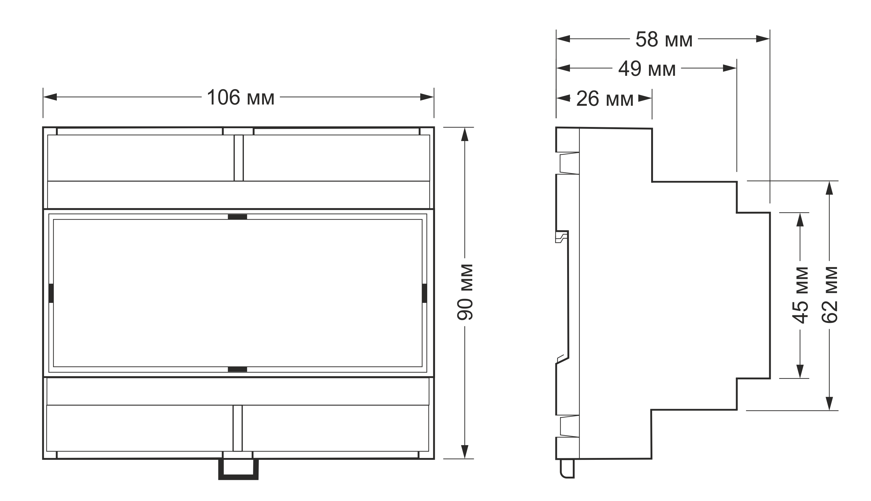
| Dimensions (L × W × H) | 106 × 90 × 58 mm |
| Weight (including box) | 215 g |
Operating principle
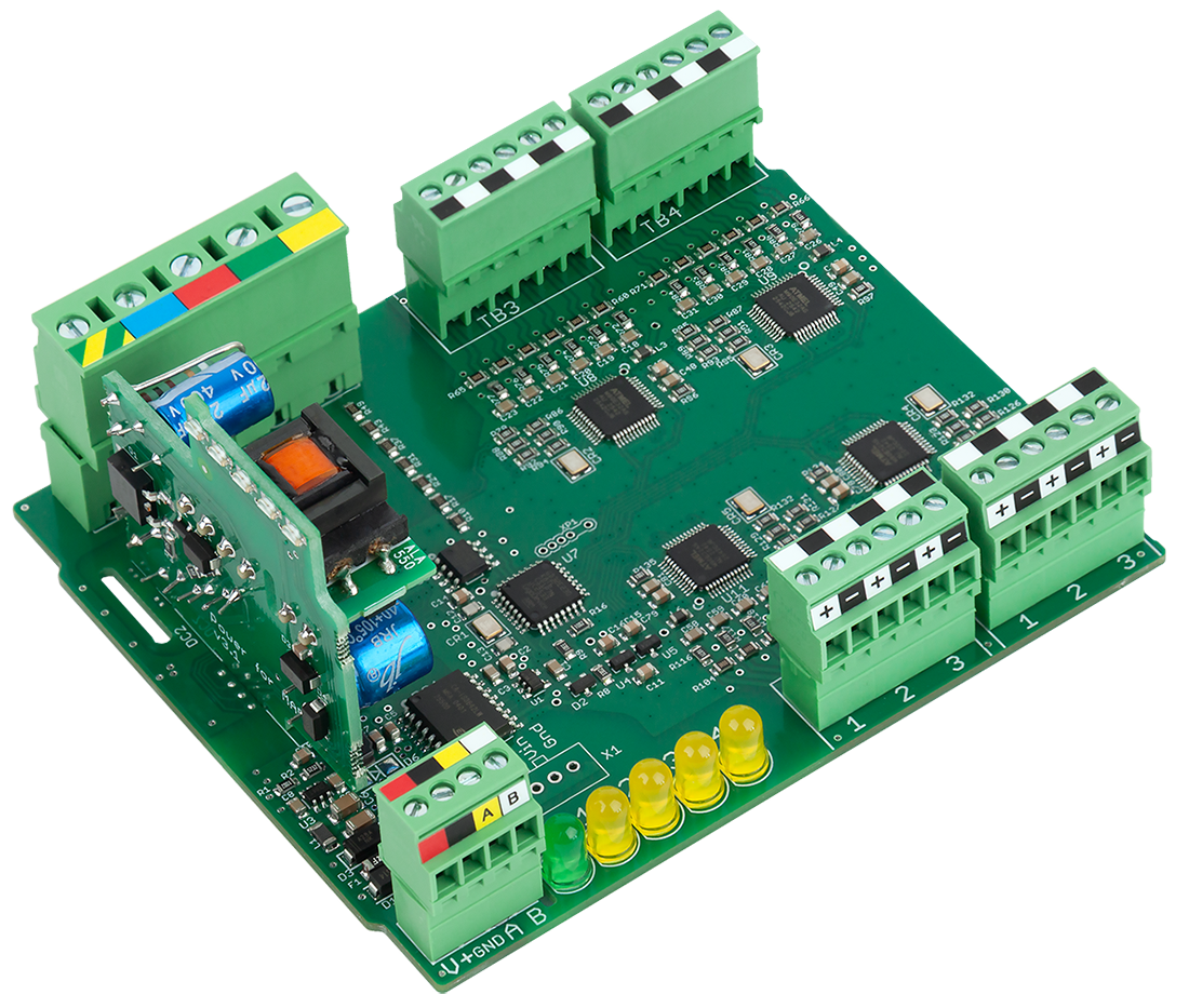
The device uses Atmel M90E32AS metering ICs with three current and voltage channels.
Each channel measures instantaneous voltage and current and multiplies them to obtain instantaneous power. The filtered product gives power and its integral gives energy. Reactive power is calculated by multiplying instantaneous current by voltage shifted by 90°.
Channels operate independently. Each measurement engine is fixed to its current input, but phase mapping can assign any of the three voltage phases to it.
Three-phase active and reactive power are the sums of the corresponding channel powers. Forward three-phase active and reactive energy are likewise sums of the respective forward channel energies.
Measurement and calculation methods:
- Urms Lx (V)— RMS voltage between Lx and N. Conventional billing meters calculate RMS directly; WB-MAP averages over 16 cycles, or every 320 ms.
- Upeak Lx inst (V) — peak voltage between Lx and N over the detection interval (20 ms by default, register 4340).
- Upeak Lx (V) — aggregated peak voltage between Lx and N. Detectable pulses start at 300 µs, as determined by the input filters. The aggregation interval is configurable (60 seconds by default, register 4336).
- U Lx-Ly (V) — line-to-line voltage between Lx and Ly, calculated using the law of cosines.
- Phase angle Lx (degrees) — signed phase angle between voltage and current on one phase, from −180° to +180°. A positive value means current lags voltage (inductive load); a negative value means it leads (capacitive load). A 0–360° display represents the same quantity differently: 348° equals −12°. The meter extracts the fundamental frequency, detects zero crossings and calculates the angle from the time difference between them.
- Voltage angle Lx (degrees)— voltage phase displacement between phases, from 0° to 360°. L1 is always 0; L2 and L3 are measured relative to L1.
- Irms Lx (A)— RMS phase current. Conventional billing meters calculate RMS directly; WB-MAP averages over 16 cycles, or every 320 ms.
- Ipeak Lx inst (A) — peak phase current over the detection interval (20 ms by default, register 4340).
- Ipeak Lx (A) — aggregated peak phase current. Detectable pulses start at 300 µs, as determined by the input filters. The aggregation interval is configurable (60 seconds by default, register 4336).
- P Lx (W)— active power, associated with the energy billed by the electricity supplier. WB-MAP and billing meters calculate it from the instantaneous voltage/current product.
- Q Lx (var)— reactive power. conventional reactive-power accuracy is specified for linear loads. Some meters display non-active power N as Q, since they coincide for linear loads, sometimes adding a sign according to the voltage/current quadrant. For non-sinusoidal currents, WB-MAP measures fundamental reactive power according to IEC 62053-24 by multiplying current by voltage shifted by 90°.
- S Lx (VA)— apparent power, defined and calculated as Irms × Urms. A load with S = 2 kVA heats conductors like a resistive load with P = 2 kW at the same voltage, because the RMS current is the same.
- N Lx (var) — non-active power, defined as N2 = S2 − P2. WB-MAP meters use this definition. It represents the component associated with conductor heating that does not perform useful work.
- PF Lx— power factor, calculated as PF = P/S: the fraction of apparent power corresponding to useful active power.
A peak value is the sine-wave amplitude, approximately 1.41 times the RMS value; a 330 V peak on a 230 V supply is therefore normal. Registers 4336 and 4340 set the aggregation and detection intervals.
Measurement circuit isolation
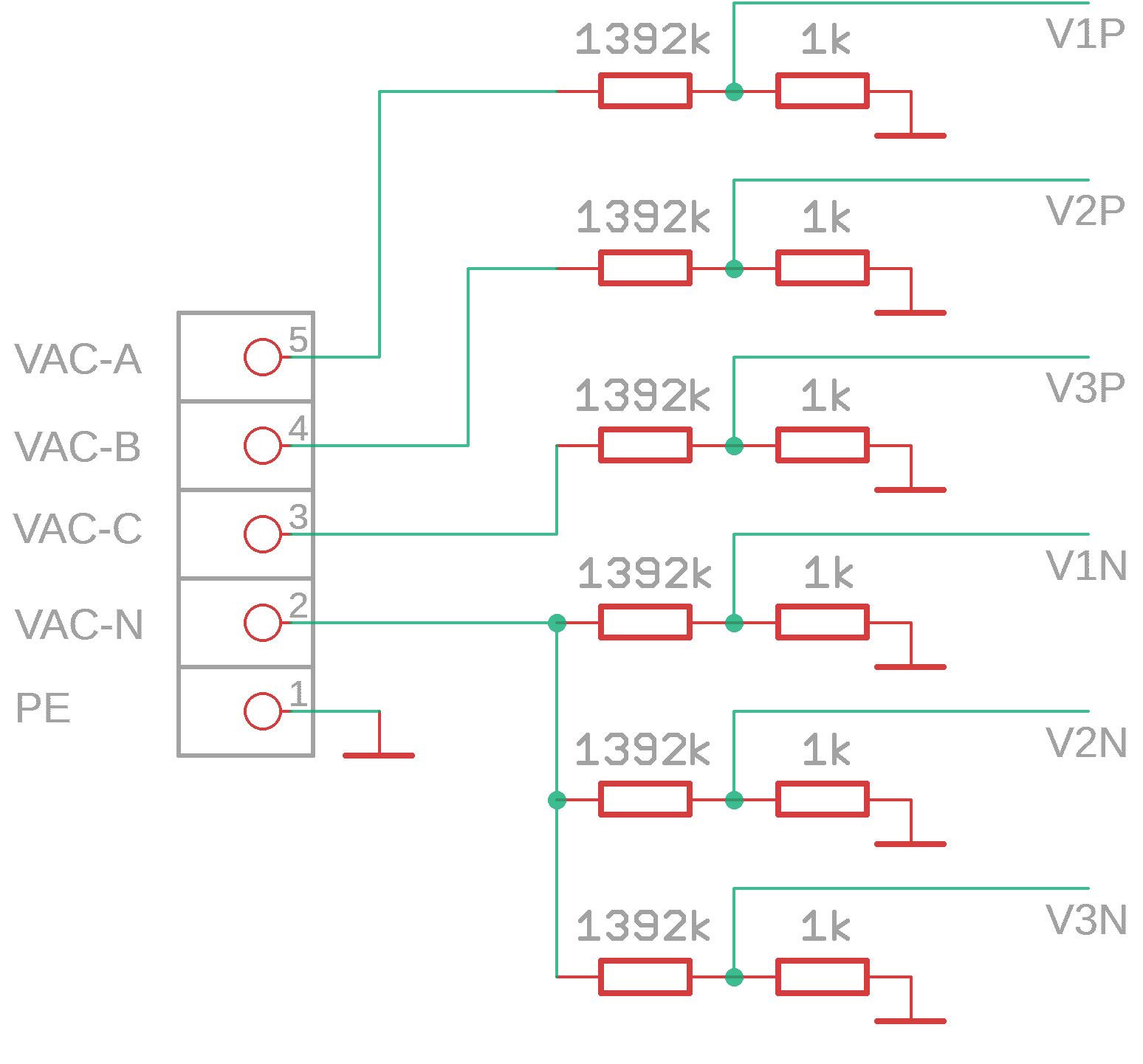
The meter uses a neutral attenuation network: the measurement circuit is attenuated from both phase conductors and neutral. The ADC reference is connected to PE rather than neutral.
Without PE connected, unused phase terminals can acquire a potential determined by the connected phase-voltage vectors and internal divider ratios. For example, with 230 V on one phase, another may sit at approximately 230 × 0.3/1.3 = 53 V.
The optional Detect disconnected phases function sets voltage and associated power readings to zero if that phase voltage is below 30% of the highest phase voltage.
Meter power supply
The meter has two power sources:
- phase-voltage supply, absent in some variants; voltage on any one phase is sufficient;
- interface-section supply.
Either source can power the measurement section. Modbus communication requires power at the interface terminals V+ and GND.
With no voltage on any phase, only current-transformer RMS current readings remain valid.
Voltage dips and interruptions
Accumulated energy is retained when meter power is removed.
Accumulated energy
The meter only accumulates energy: the accumulated value cannot be reset or changed — the energy registers are read-only.
The meter has no real-time clock, so it does not store end-of-day energy or an hourly power profile.
Calculate daily or monthly consumption, tariffs and readings that continue from a previous meter in the controller or SCADA system: subtract accumulated values at two points in time and add an initial offset when required.
Increase the history retention depth in the controller web-interface settings when longer storage is required.
Installation
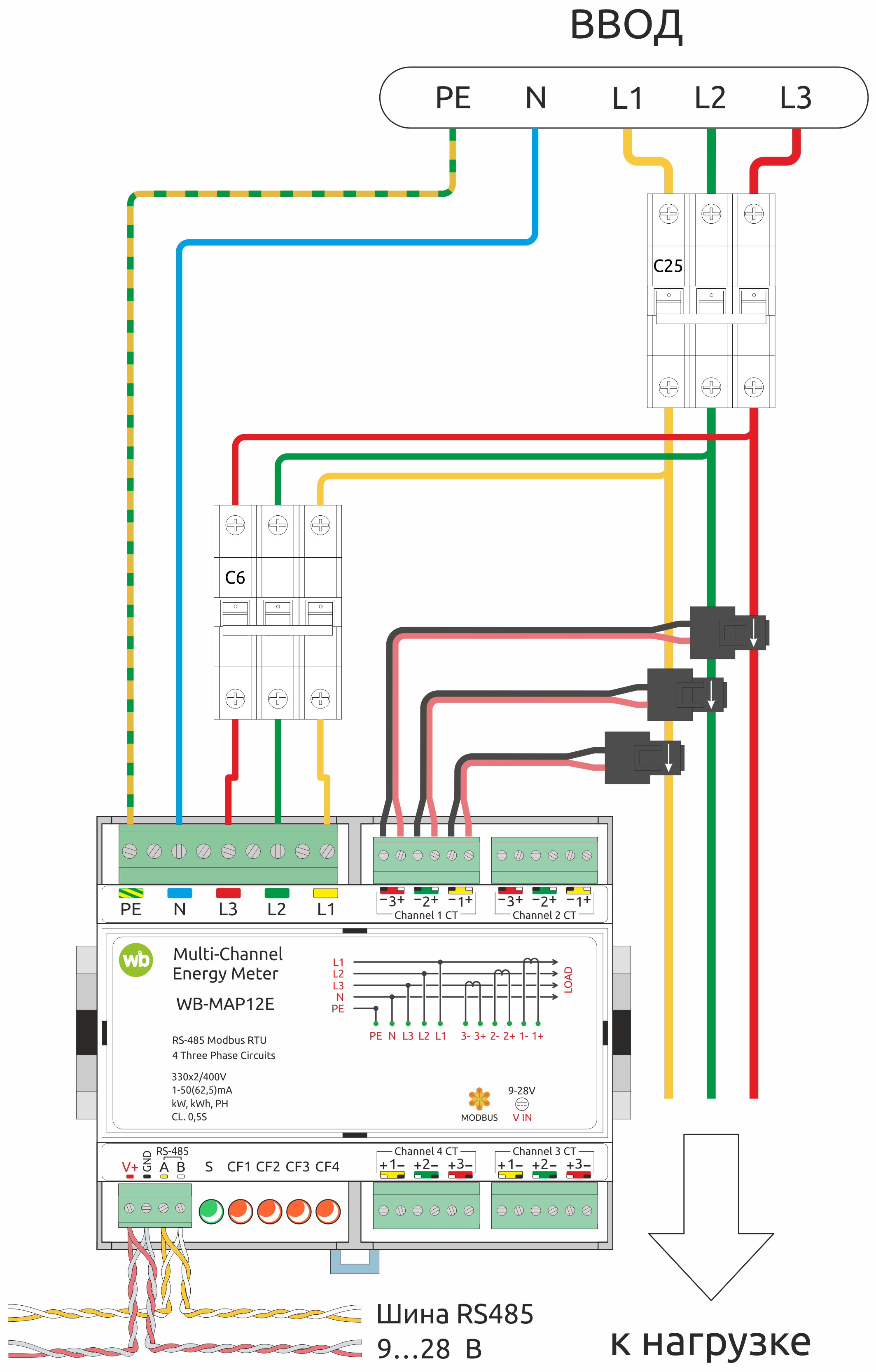
MAP meter installation instructions
Mount the meter on a standard 35 mm DIN rail. Follow the installation stages below when fitting a WB-MAP meter in an electrical cabinet.
Wiring the communication interface
The V+ GND A B terminal block, with a 3.5 mm pitch, connects the interface power supply and RS-485 bus. Correct bus topology and termination are essential for reliable communication.
If devices on the RS-485 bus use different power supplies, interconnect their GND terminals.
Wiring the high-voltage section
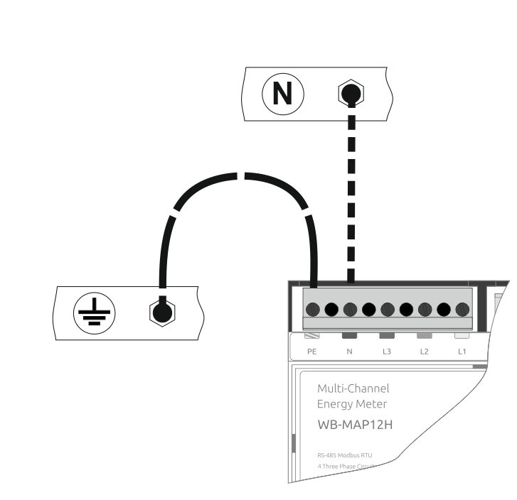
Always connect PE to protective earth and N to neutral.
Connect three phases, neutral and protective earth to the high-voltage terminal block. Connecting phases through a circuit breaker simplifies installation; choose its rating to suit the wire cross-section.
The PE conductor grounds the CT secondary circuits. Without it, accidental mains contact on one CT cable can put mains potential on all CT cables. With protective earthing connected, the RCD trips or the resistors at the current inputs burn out.
Connect L1 (A), L2 (B) and L3 (C) according to the terminal labels.
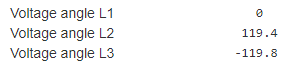
For three phases, Voltage angle readings are L1 = 0°, L2 ≈ +120°, L3 ≈ −120°, or 0°/−120°/+120°. Either phase sequence is supported.
Connection to single-phase networks
For single-phase use, connect the phase conductor to L1. L1 readings are valid; vector-sum energy and power (SV) are unavailable.
To use all current inputs, map them to the connected phase; see
The voltage inputs are high-impedance. Unused Lx inputs may pick up interference that appears as a measured voltage. Connect unused phase inputs to N to prevent this.
Connection to voltage transformer secondary circuits (57 V)
The meter supports instrument voltage-transformer secondaries, for example in 6–110 kV networks with 57.7 V phase-to-neutral and 100 V line-to-line secondary voltage.
Connect the VT secondary phase conductors to L1, L2 and L3, and neutral to N.
Because approximately 57 V is below the 90–510 V phase-supply range, power the meter through the interface section. Phase-derived power is unavailable in this arrangement.
Voltage, power and accumulated energy readings then refer to the VT secondary. Multiply them by the VT ratio to obtain primary-network values.
Connecting current transformers
Fit current transformers around the corresponding phase conductors, with each arrow pointing towards the load:
1 — L1(A), 2 — L2(B), 3 — L3(C).
If a CT was fitted backwards, its polarity can be inverted in the settings.
Connect white/red CT leads to the positive current inputs and black leads to the negative inputs. Do not join connected CT leads together or connect them to other circuits. The meter internally provides protective earthing of CT secondaries to PE.
For a preconfigured/calibrated meter, each CT is individually assigned and labelled for its channel. Connect it to that channel. If a CT is already around an energised conductor but its secondary cannot yet be connected to the meter, short its secondary leads together to prevent core buzzing and heating.
A core gap can also cause buzzing. Check that the core is firmly closed and the secondary leads are not left open.
Extending CT leads
Allow for cable resistance. Total loop resistance must not exceed 4 Ω for KCT/CTSA transformers or 14 Ω for WB-CT309 assemblies; higher resistance reduces accuracy. Keep the two CT leads together, away from power cables, and use shielded cable for extensions.
Standard copper twisted pair with 0.20 mm2 conductors has resistance of approximately 10 Ω per 100 m. Extensions are permitted up to 10 m for KCT/CTSA and 70 m for WB-CT309 using this cable. For longer runs, use a larger cross-section, for example KGVEV 7×1.0.
Shortening CT leads
Standard leads can be shortened without affecting accuracy or CT operation.
Cleaning the magnetic core
Clean the mating core faces before closing the CT around a conductor.
Fingerprints, dirt and dust create an air gap that reduces accuracy.
-
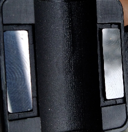 Fingerprints and dust on the core reduce measurement accuracy
-
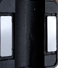 Clean magnetic core surface
Securing current transformers
Poor mechanical installation can also create a gap between the core halves.
Check that the transformer:
is closed squarely, without misalignment;
can rotate freely around the conductor.
Otherwise, mechanical stress can create an air gap, with measurement error of 10 % or more.
-
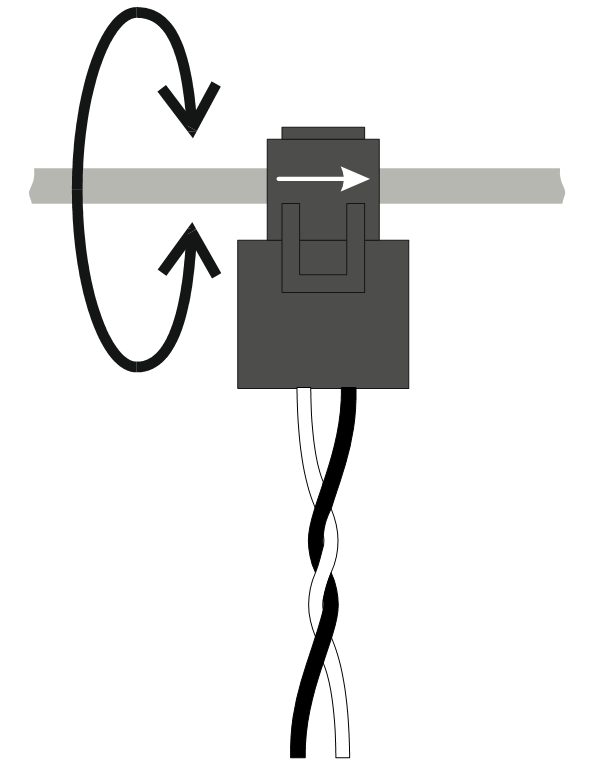 The CT should rotate freely around the conductor
-
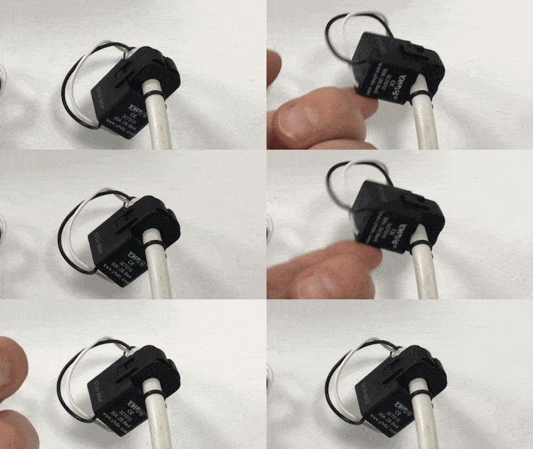 Correct fitting: CT rotates freely
-
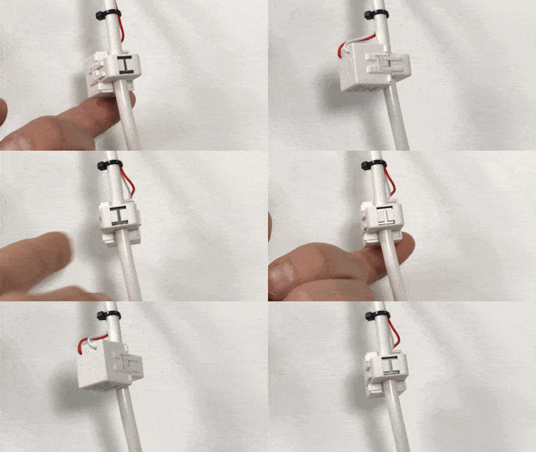 Incorrect CT fitting
Current transformer orientation
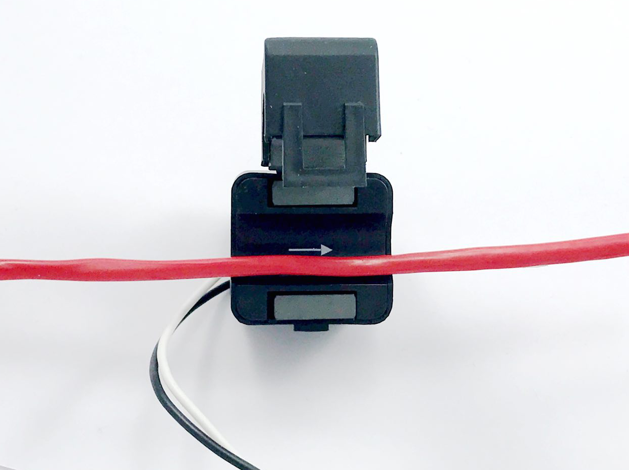
Fit each CT in the correct orientation and connect its leads with the correct polarity. For a consuming load, the arrow points along the phase conductor towards the load.
This assumes the circuit consumes energy. Some solar or wind inverters export surplus energy to the grid; externally driven motors can also generate electricity.
Without local generation, correctly oriented CTs give positive active power; reversed CTs give negative active power.
Checking the wiring
To prevent measurement errors, check the connections:
- Apply a load of approximately 100 W per phase.
- In the controller interface, check:
- the angle between current and voltage — it should be between −40° and +40°.
- active power on the phase — it should be positive.
For predominantly resistive loads such as lighting, heaters and other household appliances, voltage/current phase displacement is normally within a few tens of degrees.
Angles above 100° indicate that the CT is around the wrong phase conductor. This check may not apply to reactive-power compensation equipment or large motors.
| Observed angle | Meaning |
|---|---|
| Up to ±40° | Normal: the CT is fitted to the correct phase conductor and its direction is correct |
| Approximately ±120° | The CT is on a different phase conductor; supply phases differ by 120° |
| Approximately ±180° with negative active power | The CT is reversed: turn it around or enable Reverse current transformer |
| The angle varies between readings | The circuit has a mixed load. Test with one resistive load, such as an incandescent lamp or heater |
-
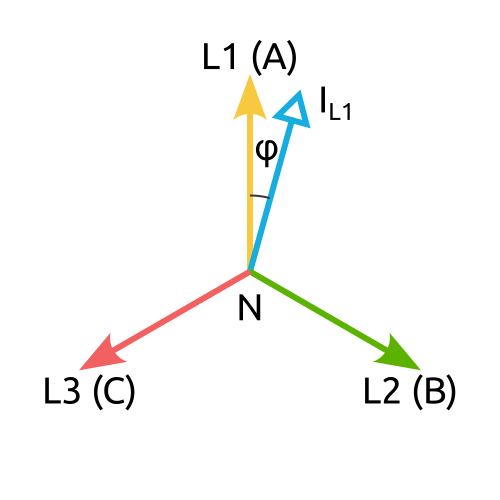 Small voltage/current phase angle: L1 CT correctly connected
-
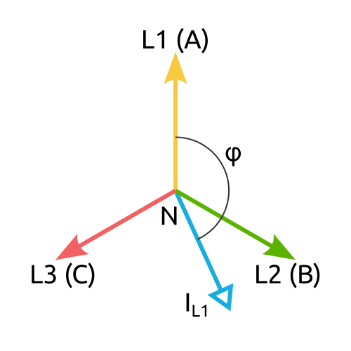 Large voltage/current phase angle: the measured current belongs to a different phase and the CT is incorrectly assigned
-
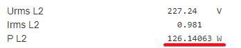 Positive active power: the phase is sufficiently loaded
-
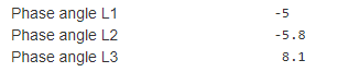 Voltage/current phase angle below 40°: CTs correctly fitted
-
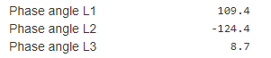 Voltage/current phase angle above 40°: L1 and L2 CTs interchanged
Using instrument transformers for high currents
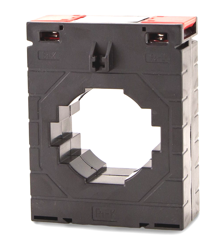
WB-MAP current inputs measure up to 60 mA RMS at the CT secondary. A 200 A/100 mA transformer can can be connected, but the measurable primary current is limited to 60 mA / 100 mA × 200 A = 120 A.
Never connect a 5 A secondary directly to a WB-MAP meter. Use an intermediate transformer such as KCT-6 or WB-CT309; a 5 A/25 mA transformer is recommended.
Fit the WB-MAP CT around a conductor in the 5 A secondary circuit. That secondary must remain short-circuited or connected to an existing meter; leaving it open can destroy the transformer.
Scale the readings in software by the additional transformation ratio. For an 800/5 A upstream CT, multiply the WB-MAP reading by 160: 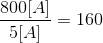 to obtain the primary value. Apply the factor to current, power and energy. Alternatively, multiply the CT ratios and write the combined value to the ratio register if it is below 65536; the meter then reports the primary values directly.
If the product exceeds 65,535, store only the intermediate-transformer ratio in the meter and multiply current, power and energy by the primary-transformer ratio in the controller. For example, WB-CT309 with a ratio of 2000 after a 200/5 A transformer gives 2000 × 40 = 80,000, which does not fit in the register.
Configuration
Configuration methods
- Set the parameters in the Wiren Board controller web interface under Settings → Configs → Serial devices driver configuration. If these menu items are unavailable, check the current access level.
- Write settings to the module’s Modbus registers from the controller console with modbus-utils-rpc or modbus_client.
- Without a Wiren Board controller, use the Wiren Board device web configurator or compatible Modbus software on a computer with a USB-to-RS-485 adapter.
Our devices are continually improved. If settings described in this manual are missing, update the device firmware and controller software.
Current transformer configuration
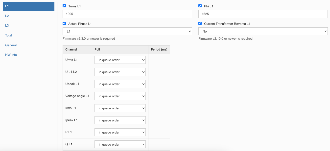
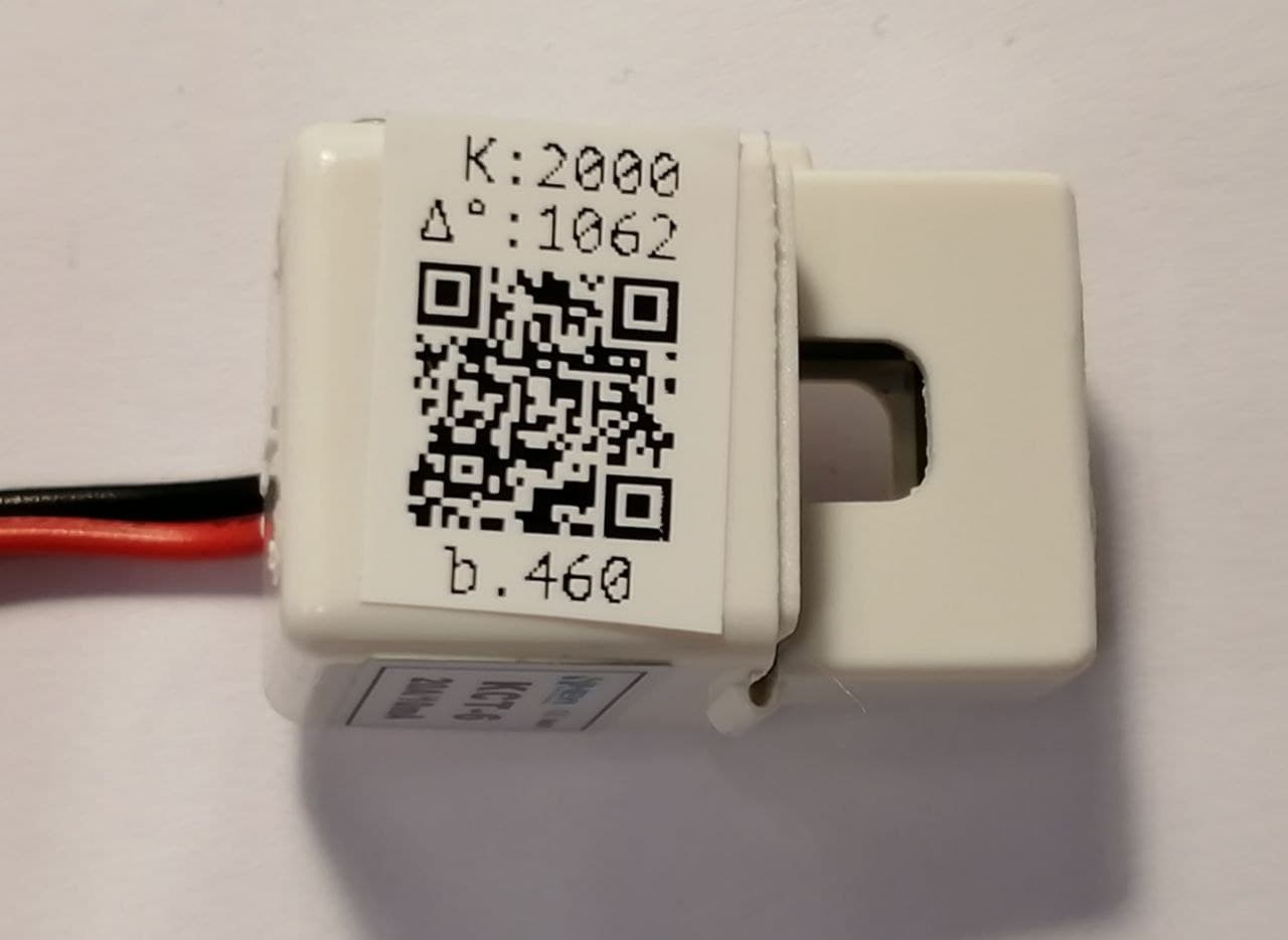
If meter configuration was ordered with the meter and CTs, CT parameters are already stored and each CT is labelled with its channel number. Connect each to that channel; otherwise readings will be incorrect.
If meter configuration was not ordered, enter the CT parameters into meter memory before use. Otherwise current, power and energy remain zero because the default transformation ratio is zero.
Wiren Board current transformers are factory calibrated. The parameter source depends on the transformer type:
| Transformer type | Where to find parameters |
|---|---|
| Split-core: KCT, CTSA, ZEMCTK | On the body label; values are individual for every transformer |
| Solid-core: ZMCT, WB-CT309 | In the model specification table; all units of one model use the same values. WB-CT309 v.2 uses 2000 and 120; ZMCT102w uses 2000 and 50 |
| Built into WB-MAP3ET | Stored in the meter at the factory; no entry is required |
Each CT has two calibration characteristics that must be entered in the meter configuration. Their documentation and web-interface names differ:
| Documentation name | Web-interface name | Meaning |
|---|---|---|
| Turns Lx | — transformation ratio, | the factor by which the transformer reduces current |
| Phi Lx | Phase correction Lx | transformer phase shift in thousandths of a degree; transformer specifications may call it phase angle or phase shift |
| Actual Phase Lx | Actual phase Lx | the supply phase to which the transformer is assigned |
Write both parameters for every CT to meter memory before operation.
Configuration Current Transformer Reverse x — inverts CT polarity.
If these settings are missing from the web interface, update the controller software or configure the CTs from the controller console.
Phase mapping configuration
Use phase mapping carefully: assigning a CT to the wrong voltage phase produces incorrect readings that may still look plausible. Each WB-MAP12E current input can be assigned to any voltage phase connected to the meter.
Phase mapping changes the factory assignment between current inputs and voltage phases. For example, current input L1 can be mapped to voltage phase L2. Use it to correct installation errors in software or to operate WB-MAP12E as a twelve-channel single-phase meter. Mapping only selects the voltage used in calculations; it does not alter wiring or power connections.
If a voltage phase has no CT assigned to it, the parameters Urms and Upeak cannot be measured and appear in red in the web interface. Measuring VoltageAngle requires the CTs to be assigned to different phases.
Set phase mapping with Actual Phase Lx — the actual voltage phase associated with the CT on current input Lx.
If these parameters are absent, update the controller software or use another method described under Configuration methods.
Indicators
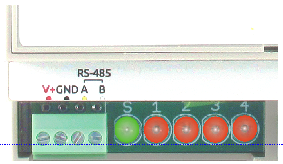
The meter has five LED indicators:
- S (green) indicates Modbus communication. It lights when low-voltage power is present and flashes during RS-485 polling. With Fast Modbus events enabled it flashes more frequently. It flashes once per second in bootloader mode and rapidly during firmware upload.
- CF1–CF4 (red) indicate accumulated consumed active energy for the four three-phase channels. Flashing represents consumption: 1000 pulses equal 1 kWh; firmware earlier than 2.1 used 3200 pulses per kWh.
Wiren Board controller web interface
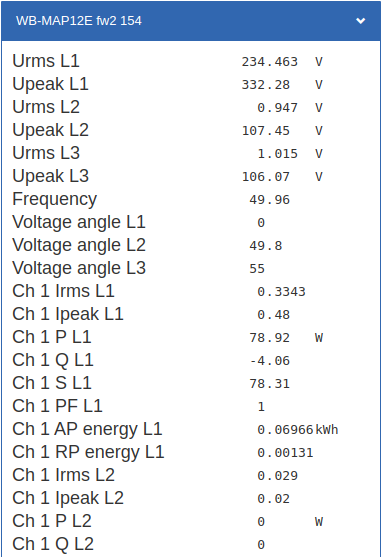
Selecting a template
To display the device on the Devices in the Wiren Board controller web interface, add it automatically through RS-485 device discovery or manually by selecting the WB-MAP12E fw2.
Viewing readings
The controller web interface displays meter readings. Choose the displayed channels in the device settings.
Modbus operation
Wiren Board devices use Modbus RTU over the physical RS-485 interface.
All main Modbus commands for reading and writing one or multiple registers are supported.
The module can be configured:
- in the Wiren Board controller web interface;
- with the Wiren Board device web configurator;
- with third-party software.
Default port settings
| Value default |
Parameter name in the web interface |
Parameter |
|---|---|---|
| 9600 | Baud rate | Baud rate, bit/s |
| 8 | Data bits | Number of data bits |
| None | Parity | Parity |
| 2 | Stop bits | Number of stop bits |
In current firmware, setting Stop bits is optional: the device also operates correctly when its number of stop bits differs from the Modbus master setting.
For a faster response, we recommend increasing the baud rate to 115200 bit/s Communication parameter settings
Modbus address
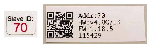
Each device on the bus must have a unique address from 1 to 247. The factory-assigned address is printed on labels on the enclosure (top cover, side or underside). Devices in a production batch are assigned different addresses, so devices in one order will usually have different addresses.
The address can be discovered, changed or reset with Wiren Board controller tools or compatible Modbus configuration software.
Fast Modbus extension
Fast Modbus extends standard Modbus with rapid discovery of Wiren Board devices on RS-485 and event polling.
These features are enabled by a special command from the master, so Wiren Board devices remain compatible with third-party equipment.
Not every register supports event generation. Check the register map: event-capable registers are marked with ⚡. See Fast Modbus.
Register map
The meter provides numerous Modbus registers for measured and calculated quantities and for device control.
Modbus registers for measured and calculated quantities
WB-MAP12E control register table
Firmware updates and resetting settings
Wiren Board devices support firmware updates over Modbus. This allows bugs to be fixed at the installation site and, where technically possible, new features to be added. Settings stored in the device are retained during a firmware update.
Instructions:
- Firmware update (video tutorial)
- Resetting settings
- Connection parameter settings
- Modbus address: find, reset or change
- Updating the bootloader
New firmware releases are listed in the firmware changelog.
Factory calibration and CT parameters are stored separately and are not erased by firmware updates.
Known issues
Known issues
Hardware revisions
Revision history
Device images and drawings