 Documentation
Ventalen DK-1-MB-B
DAIKIN S21 / Wi-Fi connector gateway — Modbus RTU
Covered order codes (1)
VA-P-DK-1-MB-B-B
The Ventalen DK-1-MB-B is a Modbus RTU gateway for control and monitoring of DAIKIN air-conditioning systems with an S21 or Wi-Fi connector. It also supports Fast Modbus. It is intended for split, ducted and floor-standing systems. Product range: Ventalen AIR; series: PRO; hardware version: B. Order code: VA-P-DK-1-MB-B-B.
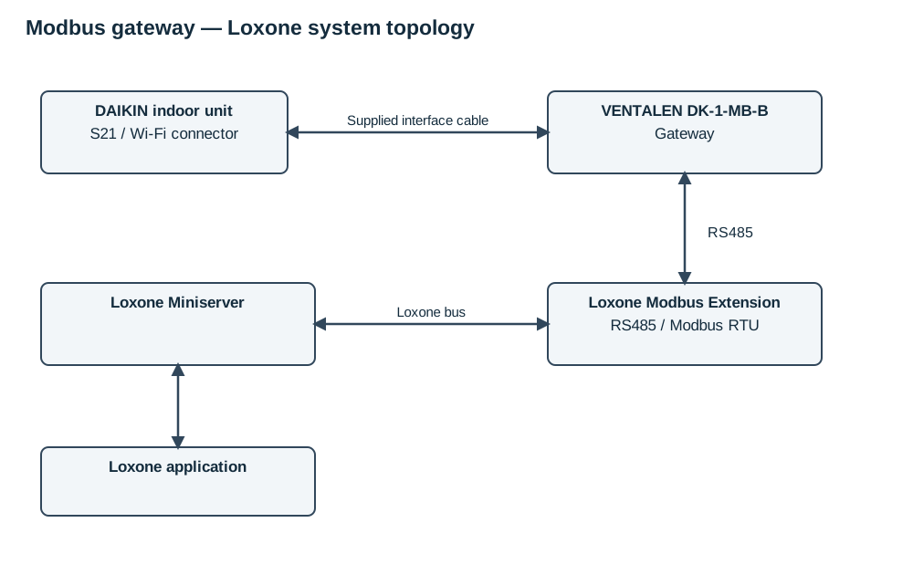
Wiren Board integration is included from release wb-2310; earlier releases require a device template. Loxone integration uses a device template and a Loxone Modbus Extension.
2. Technical specifications
| Interface | RS485 |
| Interface isolation | Galvanically isolated |
| Protocol | Modbus RTU + Fast Modbus; software-configurable address. Factory settings are printed on the label. |
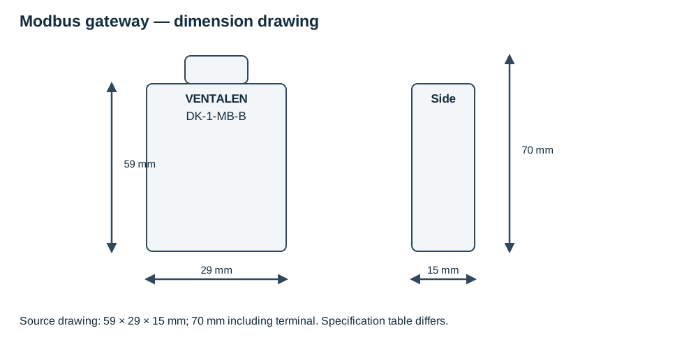
| Dimensions | 60 × 36 × 15 mm (L × W × H), excluding terminal block 70 × 36 × 15 mm (L × W × H), including terminal block |
| Recommended power supply | 24 V DC |
| Baud rate | 9600 (default), 19200, 38400, 57600, 115200 |
| Stop bits | 2 |
| Parity | None (N) |
| Power consumption | 1 W maximum |
| Bus and power connection | Screw terminal block |
| Recommended conductor cross-section with insulated wire-end ferrules | 0.35–1 mm² — single conductors 0.35–0.5 mm² — twin conductors |
| Screw tightening torque | 0.2 N·m |
| Operating mode | Continuous |
| Operating temperature | 0 to +40 °C |
| Ingress protection | IP30 |
| Weight (including packaging) | 85 g |
| Package contents | Box, device, two cables |
2.1 Hardware versions
| Version | Production period | Changes |
|---|---|---|
| B | September 2024 onwards | New gateway platform with Fast Modbus support; new enclosure; updated processor and components; changed RS-485 connection pinout; illuminated button showing operating status. |
| A.2 | December 2023–August 2024 | Minor changes to PCB components. |
| A.1 | July–December 2023 | Initial device version. |
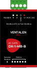
2.2 Device drawing
2.3 Package contents
Box, gateway and two connection cables.
2.4 Dimensions
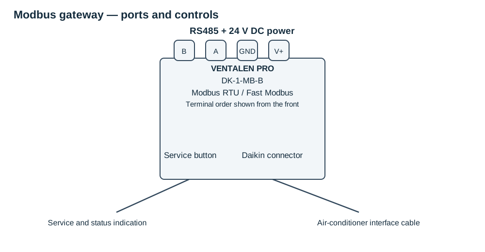
2.5 Ports and buttons
3. Device appearance
The gateway has a compact enclosure with a removable screw terminal block for the RS-485 bus and DC power, an air-conditioner interface connector and an illuminated status button. Identify the hardware version before connecting it: version B has a different RS-485 pinout from earlier versions.
4. Quick start
- Disconnect power from both the air conditioner and gateway before making connections.
- Connect the gateway to the air conditioner's S21 connector using the appropriate cable.
- Check all connections before applying power.
- Use the recommended 24 V DC supply for the gateway.
- Do not install the device in damp locations.
4.1 Troubleshooting
- Check the air-conditioner interface cable: both connectors must be fully inserted, neither connector may be broken, and all conductors must be retained correctly at both ends.
- Check the gateway power supply. Measure the voltage at the terminal block if necessary.
- Check the A and B conductors of the RS-485 bus at both the gateway and the controller.
- Check that the RS-485 terminal block is fully inserted into the gateway.
- Check that the cable is suitable for an RS-485 bus.
4.2 Changing the baud rate
Write the required baud rate divided by 100 to holding register 110. For example, write 1152 for 115200 bit/s.
On Wiren Board, with wb-mqtt-serial stopped, this command sets the gateway at address 12 on RS485-1 to 115200 bit/s. The existing baud rate is 9600 bit/s:
modbus_client --debug -mrtu -b9600 -pnone -s2 /dev/ttyRS485-1 -a12 -t0x06 -r110 1152Update the controller port settings to match the new gateway settings before resuming polling.
4.3 Changing the Modbus address
The factory default address is 1. Write the new address to holding register 128. Valid addresses are 1–247. With wb-mqtt-serial stopped, the following command changes the address from 1 to 12 on RS485-1:
modbus_client --debug -mrtu -b9600 -pnone -s2 /dev/ttyRS485-1 -a1 -t0x06 -r128 125. Modbus register map
The full register map is embedded below, including the service registers from the separate register-map document. R = read-only; RW = read/write. Addresses are decimal and hexadecimal protocol addresses.
| Address (dec) | Address (hex) | Type | Access | Format | Description | Values |
|---|---|---|---|---|---|---|
| Coils | ||||||
| 1 | 0x0001 | Coil | RW | Bool | Power | 0 - Disabled 1 - Enabled |
| 2 | 0x0002 | Coil | RW | Bool | Display backlight | 0 - Disabled 1 - Enabled |
| 3 | 0x0003 | Coil | RW | Bool | Dim display | 0 — High brightness 1 — Low brightness |
| 4 | 0x0004 | Coil | RW | Bool | Quiet mode | 0 - Disabled 1 - Enabled |
| 6 | 0x0006 | Coil | RW | Bool | Eco mode | 0 - Disabled 1 - Enabled |
| 7 | 0x0007 | Coil | RW | Bool | Turbo mode | 0 - Disabled 1 - Enabled |
| 20 | 0x0014 | Coil | R | Bool | AC connected | 0 - No 1 - Yes |
| 100 | 0x0064 | Coil | RW | Bool | Allow the use of an external temperature sensor | 0 - No 1 - Yes |
| Holding registers | ||||||
| 1 | 0x0001 | Holding | RW | UInt16 | Mode | 1 - Heat 2 - Cool 3 - Auto 4 - Dry 5 - Fan |
| 2 | 0x0002 | Holding | RW | UInt16 | Active mode This register helps integration in systems where disconnect is controlled by the same register as mode. | 0 - Off 1 - Heat 2 - Cool 3 - Auto 4 - Dry 5 - Fan |
| 3 | 0x0003 | Holding | RW | SInt16 | Indoor air temperature °C By default, this register stores the air temperature measured by the air conditioner's built-in sensor. When the temperature from an external sensor is written to this register, the value will be returned with a correction, which is displayed in register 20. | -32768...32768 To get the temperature, multiply the value by 0.01. For example, 2560 is 25.6 °C. |
| 4 | 0x0004 | Holding | R | SInt16 | Outdoor air temperature °C | -32768...32768 To get the temperature, multiply the value by 0.01. For example, 2560 is 25.6 °C. |
| 5 | 0x0005 | Holding | RW | SInt16 | Target temperature °C The temperature is set with an accuracy of 0.5°C | 1600...3200 To get the temperature, multiply the value by 0.01. For example, 2500 is 25.0 °C. |
| 6 | 0x0006 | Holding | R | UInt16 | Thermostat state | 0 - Idle 1 - Heat 2 - Cool |
| 7 | 0x0007 | Holding | RW | UInt16 | Fan speed | 0 - Auto 1 - 1 speed 2 - 2 speed 3 - 3 speed 4 - 4 speed 5 - 5 speed |
| 8 | 0x0008 | Holding | RW | Uint16 | Smart fan speed This register helps to integrate into systems where only one register can be used for speed control. Enabling the silent and turbo modes does not change the fan speed status (displayed on the air conditioner screen and in Holding register #7) | 0 - Auto 1 - Quiet mode 2 - 1 speed 3 - 2 speed 4 - 3 speed 5 - 4 speed 6 - 5 speed 7 - Turbo mode |
| 9 | 0x0009 | Holding | RW | Uint16 | Horizontal vanes | 0 - Stop 1 - Swing |
| 10 | 0x000A | Holding | RW | Uint16 | Vertical vanes | 0 - Stop 1 - Swing |
| 11 | 0x000B | Holding | RW | Uint16 | Airflow direction This register helps to integrate into systems where only one register can be used to control the airflow direction. | 0 - Stop 1- Horizontal and vertical swing 2 - Swinging horizontal vanes 3 - Swinging vertical vanes |
| 15 | 0x000F | Holding | RW | UInt16 | Mode (for Loxone) | 1 - Auto 2 - Heat 3 - Cool 4 - Dry 5 - Fan |
| 20 | 0x0014 | Holding | RW | SInt16 | Temperature correction | -32768...32768 To get the temperature, multiply the value by 0.01. For example, 100 is 1.00 °C. |
| 31 | 0x001F | Holding | R | SInt16 | Target fan speeds (RPM) | 0...200 |
| 32 | 0x0020 | Holding | R | SInt16 | Current fan speeds (RPM) | 0...200 |
| Service holding registers | ||||||
| 110 | 0x006E | Holding | RW | SInt16 | Baud rate | To get the real speed, you need to multiply the values from the register by 100, to write the desired value, you need to divide it by 100. 96 - 9600 192 - 19200 384 - 38400 576 - 57600 1152 - 115200 |
| 111 | 0x006F | Holding | RW | UInt16 | Parity bit | 0 - no parity bit (none), 1 - odd, 2 - even. |
| 112 | 0x0070 | Holding | RW | UInt16 | Number of stop bits | 1, 2 |
| 128 | 0x0080 | Holding | RW | UInt16 | Modbus address | 1...247 |
| 200 - 219 | 0x00C8 - 0x00DB | Holding | R | String | Hardware version | DK-1-MB-B |
| 250 - 265 | 0x00FA- 0x0109 | Holding | R | String | Firmware version | 0.4.7 and later |
| 270 - 271 | 0x010E - 0x010F | Holding | R | UInt32 | Serial number | |
| 290 - 301 | 0x0122 - 0x012D | Holding | R | String | Signature | ok_dk1b |
| 400 - 420 | 0x0190 - 0x01A4 | Holding | R | String | Air-conditioner protocol version | 2.0.13 (listed version) |
6. Downloads
- Ventalen DK-1-MB-B template for Wiren Board (JSON)
- Ventalen DK-1-MB-B template for Loxone (XML)
- English Modbus register map (CSV)
7. Warranty
The stated warranty period is six years from sale through a retailer, retail representative or integrator. The warranty and service-life periods start when the product is handed over to the customer. If that date cannot be established, they start on the date of manufacture.
The warranty does not cover gateways or parts with signs of mechanical damage, liquid ingress, burning or opening; incomplete product sets; or faults caused by transport damage, careless handling, poor maintenance, incorrect installation or repair, work by unqualified personnel, or causes outside the manufacturer's control, such as incorrect bus voltage, fire, flooding or other force-majeure events. Warranty replacement and repairs are handled at the seller's premises.
8. Supported DAIKIN air conditioners
The series and model designations below follow the compatibility lists.
8.1 2024 models
| Series of air conditioners |
Air conditioner model |
| Split systems | |
| Wall-mounted Ururu Sarara (FTXZ-N/RXZ-N) | FTXZ25N | RXZ25N |
| FTXZ35N | RXZ35N | |
| FTXZ50N | RXZ50N | |
| Wall-mounted Emura (FTXJ-A/RXJ-A) | FTXJ20AW/S/B | RXJ20A |
| FTXJ25AW/S/B | RXJ25A | |
| FTXJ35AW/S/B | RXJ35A | |
| FTXJ42AW/S/B | RXJ42A | |
| FTXJ50AW/S/B | RXJ50A | |
| Wall-mounted Perfera (FTXM-R/RXM-R(9) CTXM-R) | CTXM15R | MXM-A |
| FTXM20R | RXM20R9 | |
| FTXM25R | RXM25R9 | |
| FTXM35R | RXM35R9 | |
| FTXM42R | RXM42R | |
| FTXM50R | RXM50R | |
| FTXM60R | RXM60R | |
| FTXM71R | RXM71R | |
| Wall-mounted Sensira (FTXF-E/RXF-E) | FTXF20E | RXF20E |
| FTXF25E | RXF25E | |
| FTXF35E | RXF35E | |
| FTXF42E | RFX42E | |
| Wall-mounted Sensira (FTXF-D/RXF-D) | FTXF20D | RXF20D |
| FTXF25D | RXF25D | |
| FTXF35D | RXF35D | |
| FTXF42D | RFX42D | |
| FTXF50D | RXF50D | |
| FTXF60D | RXF60D | |
| FTXF71D | RXF71D | |
| Wall-mounted Sensira (FTXF-C(A)/RXF-C(B,A)) | FTXF20C | RXF20C |
| FTXF25C | RXF25C | |
| FTXF35C | RXF35C | |
| FTXF42C | RXF42C | |
| FTXF50A | RXF50B | |
| FTXF60A | RXF60B | |
| FTXF71A | RXF71A | |
| Floor-standing Perfera (FVXM-A/RXM-R(9) CVXM-A) | CVXM20A | MXM-A |
| FVXM25A | RXM25R9 | |
| FVXM35A | RXM35R9 | |
| FVXM50A | RXM50R | |
| Sky Air split systems (R-32) | |
| Wall-mounted Perfera (FTXM-R/RZAG-A) | FTXM35R | RZAG35A |
| FTXM50R | RZAG50A | |
| FTXM60R | RZAG60A | |
| Multi-split systems | |
| Wall-mounted (FTXP-N) | FTXP20N |
| FTXP25N | |
| FTXP35N | |
| Wall-mounted (FTXF-B(A)(E)) | FTXF20B |
| FTXF25B | |
| FTXF35A | |
| FTXF20E | |
| FTXF25E | |
| FTXF35E | |
| FTXF42E | |
| Wall-mounted (FTXJ-MW(MS)) | FTXJ20MW |
| FTXJ25MW | |
| FTXJ35MW | |
| FTXJ50MW | |
8.2 2022 models
| Series of air conditioners |
Air conditioner model |
| Split systems | |
| Wall-mounted Emura (FTXJ-A/RXJ-A) | FTXJ20AW/S/B | RXJ20A |
| FTXJ25AW/S/B | RXJ25A | |
| FTXJ35AW/S/B | RXJ35A | |
| FTXJ42AW/S/B | RXJ42A | |
| FTXJ50AW/S/B | RXJ50A | |
| Wall-mounted Emura (FTXJ-MW(MS)/RXJ-M9(N)) | FTXJ20M-W/S | RXJ20M9 |
| FTXJ25M-W/S | RXJ25M9 | |
| FTXJ35M-W/S | RXJ35M9 | |
| FTXJ50M-W/S | RXJ50N | |
| Wall-mounted Perfera (FTXM-R/RXM-R(9) CTXM-R) | CTXM15R | MXM-A |
| FTXM20R | RXM20R9 | |
| FTXM25R | RXM25R9 | |
| FTXM35R | RXM35R9 | |
| FTXM42R | RXM42R | |
| FTXM50R | RXM50R | |
| FTXM60R | RXM60R | |
| FTXM71R | RXM71R | |
| Wall-mounted Comfora (FTXP-M(9)/RXP-M) | FTXP20M9 | RXP20M |
| FTXP25M9 | RXP25M | |
| FTXP35M9 | RXP35M | |
| FTXP50M | RXP50M | |
| FTXP60M | RXP60M | |
| FTXP71M | RXP71M | |
| Wall-mounted Sensira (FTXF-C(A)/RXF-C(B,A)) | FTXF20C | RXF20C |
| FTXF25C | RXF25C | |
| FTXF35C | RXF35C | |
| FTXF42C | RXF42C | |
| FTXF50A | RXF50B | |
| FTXF60A | RXF60B | |
| FTXF71A | RXF71A | |
| Wall-mounted Sensira (FTXF-D/RXF-D) | FTXF20D | RXF20D |
| FTXF25D | RXF25D | |
| FTXF35D | RXF35D | |
| FTXF42D | RFX42D | |
| FTXF50D | RXF50D | |
| FTXF60D | RXF60D | |
| FTXF71D | RXF71D | |
| Wall-mounted (FTYN-L/RYN-L) | FTYN20L | RYN20L |
| FTYN25L | RYN25L | |
| FTYN35L | RYN35L | |
| FTYN50L | RYN50L | |
| FTYN60L | RYN60L | |
| Floor-standing Perfera (FVXM-A/RXM-R(9) CVXM-A) | CVXM20A | MXM-A |
| FVXM25A | RXM25R9 | |
| FVXM35A | RXM35R9 | |
| FVXM50A | RXM50R | |
| Sky Air split systems (R-32) | |
| Wall-mounted Perfera (FTXM-R/RZAG-A) | FTXM35R | RZAG35A |
| FTXM50R | RZAG50A | |
| FTXM60R | RZAG60A | |
| Multi-split systems | |
| Wall-mounted (FTXF-B(A)) | FTXF20B |
| FTXF25B | |
| FTXF35A | |
8.3 2021 models
| Series of air conditioners |
Air conditioner model |
| Split systems | |
| Wall-mounted Emura (FTXJ-MW(MS)/RXJ-M(N)) | FTXJ20M-W/S | RXJ20M |
| FTXJ25M-W/S | RXJ25M | |
| FTXJ35M-W/S | RXJ35M | |
| FTXJ50M-W/S | RXJ50N | |
| Wall-mounted Perfera (FTXM-R/RXM-R(9), CTXM-R) | CTXM15R | MXM-A |
| FTXM20R | RXM20R9 | |
| FTXM25R | RXM25R9 | |
| FTXM35R | RXM35R9 | |
| FTXM42R | RXM42R | |
| FTXM50R | RXM50R | |
| FTXM60R | RXM60R | |
| FTXM71R | RXM71R | |
| Wall-mounted Comfora (FTXP-K3(L)/RXP-L) | FTXP20K3/L | RXP20L |
| FTXP25K3/L | RXP25K3/L | |
| FTXP35K3/L | RXP35L | |
| Wall-mounted Comfora (FTXP-M(9)/RXP-M) | FTXP20M9 | RXP20M |
| FTXP25M9 | RXP25M | |
| FTXP35M9 | RXP35M | |
| FTXP50M | RXP50M | |
| FTXP60M | RXP60M | |
| FTXP71M | RXP71M | |
| Wall-mounted Sensira (FTXF-B(A)(E)) | FTXF20B |
| FTXF25B | |
| FTXF35A | |
| FTXF50A | RXF50B | |
| FTXF60A | RXF60B | |
| FTXF71A | RXF71A | |
| Wall-mounted Sensira (FTXF-C/RXF-C, CTXF-C) | CTXF20C | MXF-A(9) |
| CTXF25C | MXF-A(9) | |
| CTXF35C | MXF-A(9) | |
| FTXF20C | RXF20C | |
| FTXF25C | RXF25C | |
| FTXF35C | RXF35C | |
| FTXF42C | RXF42C | |
| Wall-mounted (FTYN-L/RYN-L) | FTYN20L | RYN20L |
| FTYN25L | RYN25L | |
| FTYN35L | RYN35L | |
| FTYN50L | RYN50L | |
| FTYN60L | RYN60L | |
| Floor-standing Perfera (FVXM-A/RXM-R CVXM-A) | CVXM20A | MXM-A |
| FVXM25A | RXM25R | |
| FVXM35A | RXM35R | |
| FVXM50A | RXM50R | |
| Sky Air split systems (R-32) | |
| Wall-mounted Perfera (FTXM-R/RZAG-A) | FTXM35R | RZAG35A |
| FTXM50R | RZAG50A | |
| FTXM60R | RZAG60A | |
8.4 2020 models
| Series of air conditioners |
Air conditioner model |
| Split systems | |
| Wall-mounted Emura (FTXJ-MW(MS)/RXJ-M(N)) | FTXJ20M-W/S | RXJ20M |
| FTXJ25M-W/S | RXJ25M | |
| FTXJ35M-W/S | RXJ35M | |
| FTXJ50M-W/S | RXJ50N | |
| Wall-mounted Emura (FTXG-L/RXG-L) | FTXG20LW/S | RXG20L |
| FTXG25LW/S | RXG25L | |
| FTXG35LW/S | RXG35L | |
| FTXG50LW/S | RXG50L | |
| Wall-mounted Perfera (FTXM-N/RXM-N(9), CTXM-N) | CTXM15N | MXM-M |
| FTXM20N | RXM20N9 | |
| FTXM25N | RXM25N9 | |
| FTXM35N | RXM35N9 | |
| FTXM42N | RXM42N9 | |
| FTXM50N | RXM50N9 | |
| FTXM60N | RXM60N9 | |
| FTXM71N | RXM71N | |
| Wall-mounted Perfera (FTXS-K/RXS-L3, CTXS-K) | FTXS20K | RXS20L3 |
| FTXS25K | RXS25L3 | |
| CTXS15K | |
| CTXS35K | |
| Wall-mounted Perfera (FTXS-K/RXS-L(3)) | FTXS35K | RXS35L3 |
| FTXS42K | RXS42L | |
| FTXS50K | RXS50L | |
| Wall-mounted Perfera (FTXS-G/RXS-L/F8) | FTXS60G | RXS60L |
| FTXS71G | RXS71F8 | |
| Wall-mounted Comfora (FTXP-K3(L)/RXP-K3(L)) | FTXP20K3/L | RXP20K3/L |
| FTXP25K3/L | RXP25K3/L | |
| FTXP35K3/L | RXP35K3/L | |
| FTXP50K3/L | RXP50K3/L | |
| FTXP60K3/L | RXP60K3/L | |
| FTXP71K3/L | RXP71K3/L | |
| Wall-mounted Comfora (FTXP-M(9)/RXP-M) | FTXP20M9 | RXP20M |
| FTXP25M9 | RXP25M | |
| FTXP35M9 | RXP35M | |
| FTXP50M | RXP50M | |
| FTXP60M | RXP60M | |
| FTXP71M | RXP71M | |
| Wall-mounted Sensira (FTXF-A(B)/RXF-A(B)) | FTXF20B | RXF20B |
| FTXF25B | RXF25B | |
| FTXF35A | RXF35A | |
| FTXF50A | RXF50B | |
| FTXF60A | RXF60B | |
| FTXF71A | RXF71A | |
| Wall-mounted Sensira (FTXB-C/RXB-C) | FTXB20C | RXB20C |
| FTXB25C | RXB25C | |
| FTXB35C | RXB35C | |
| FTXB50C | RXB50C | |
| FTXB60C | RXB60C | |
| Wall-mounted (FTYN-L/RYN-L) | FTYN20L | RYN20L |
| FTYN25L | RYN25L | |
| FTYN35L | RYN35L | |
| FTYN50L | RYN50L | |
| FTYN60L | RYN60L | |
| Universal (FLXS-B(9)/RXS-L(3)) | FLXS25B | RXS25L3 |
| FLXS35B9 | RXS35L3 | |
| FLXS50B | RXS50L | |
| FLXS60B | |
| Floor-standing Nexura (FVXG-K/RXG-L) | FVXG25K | RXG25L |
| FVXG35K | RXG35L | |
| FVXG50K | RXG50L | |
| Floor-standing (FVXM-F/RXM-N9) | FVXM25F | RXM25N9 |
| FVXM35F | RXM35N9 | |
| FVXM50F | RXM50N9 | |
| Floor-standing (FVXS-F/RXS-L(3)) | FVXS25F | RXS25L3 |
| FVXS35F | RXS35L3 | |
| FVXS50F | RXS50L | |
| Sky Air split systems (R-32) | |
| Wall-mounted Perfera (FTXM-N/RZAG-A) | FTXM35N | RZAG35A |
| FTXM50N | RZAG50A | |
| FTXM60N | RZAG60A | |
9. Air conditioner functions
The following overview describes the controls exposed in the Wiren Board interface. Available functions depend on the connected air conditioner. Interface enumeration values can differ from raw Modbus register values: use section 5 for direct Modbus access.
| Air conditioner functions | Web interface WirenBoard |
|
| Temperature control | Cooling: +18 to +30 °C Heating: +18 to +30 °C |
✅ |
|
|
On Off |
✅ |
| Operating mode | 1 — Heating 2 — Cooling 3 — Automatic 4 — Fan only 5 — Dry |
✅ |
|
|
0 — Air conditioner off 1 — On, heating 2 — On, cooling 3 — On, automatic 4 — On, fan only 5 — On, dry |
✅ |
| Indoor air temperature | Current temperature measured by the air conditioner. | ✅ |
| Outdoor air temperature | Current temperature measured by the air conditioner. | ✅ |
| Temperature setpoint The required temperature sent to the air conditioner. | Minimum: 18 Maximum: 30 |
✅ |
|
|
0 — Idle 1 — Heating 2 — Cooling |
✅ |
|
|
0 — Automatic speed 1 — Speed 1 2 — Speed 2 3 — Speed 3 |
✅ |
| Horizontal vanes Controls horizontal vanes (up/down airflow). | 0 — Stopped 1 — Swing 2 — Position 1 (lowest) 3 — Position 2 4 — Position 3 5 — Position 4 6 — Position 5 (highest) |
✅ |
|
Vertical vanes
- Controls vertical vanes (left/right airflow). |
0 — Stopped 1 — Swing 2 — Position 1 (leftmost) 3 — Position 2 4 — Position 3 5 — Position 4 6 — Position 5 (rightmost) |
✅ |
|
Vertical and horizontal vanes
Controls simultaneous or individual vane swing. |
0 — Stopped 1 — Vertical and horizontal swing 2 — Vertical vane swing 3 — Horizontal vane swing |
✅ |
|
|
On Off |
✅ |
| Dim display | On Off |
✅ |
| Extended fan speed Controls fan speed. | 0 — Automatic speed 1 — Quiet 2 — Speed 1 3 — Speed 2 4 — Speed 3 5 — Turbo |
✅ |
| Quiet mode | On Off |
✅ |
| Eco mode | On Off |
✅ |
| Turbo mode | On Off |
✅ |
| Temperature correction | Service parameter | ✅ |
| Turn display off when power is off Controls information displayed on the air conditioner's display. | Yes — The backlight turns off with the air conditioner and turns on when it starts. No — Switching the air conditioner on or off does not change the backlight state. |
❌ |
|
|
Minimum: 1 Maximum: 247 |
✅ |
| Hardware version | Current gateway hardware revision. | ✅ |
| Firmware version | Current gateway firmware version. | ✅ |
10. System architecture
The gateway bridges the air conditioner's control interface to a Modbus RTU master over RS-485. A Wiren Board controller or Loxone Modbus Extension reads status and sends control commands through the gateway.
10.2 Loxone
11. Wiring diagrams
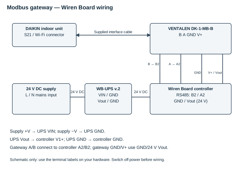
11.1 Wiren Board
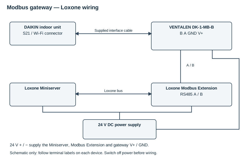
11.2 Loxone
12. Configuration
12.1 Connecting to Wiren Board
12.1.1 Example controller
The configuration example uses a Wiren Board 7, revision 7.3.3E/11 675, running wb-2304 on the release branch. On releases with built-in support, first check the available device templates before installing a custom one.
12.1.2 Uploading the template
- Download the local English device template.
- Open an SFTP client such as ForkLift. Start a connection to the controller's local IP address; the example uses
192.168.56.11. Use the controller's credentials. The original example usesrootand the factory passwordwirenboard. - The initial directory in the example is
/mnt/data/root. Go up to/mnt/data, then openetc→wb-mqtt-serial.conf.d→templates. - Copy the JSON file to
/mnt/data/etc/wb-mqtt-serial.conf.d/templates/.
12.1.3 Adding the DAIKIN gateway
- Open the controller's local IP address in a browser.
- Select Settings → Configs → Serial device driver configuration.
- Select the serial port to which the gateway is connected; the example uses
/dev/ttyRS485-1. - Set 9600 bit/s, no parity, eight data bits and two stop bits (8N2), unless the gateway has been reconfigured.
- Click Add device and select Ventalen AIR DK-1-MB-B, the adapter for domestic and light-commercial Daikin systems.
- Enter the gateway's actual Modbus address. The example uses
2; this is not the default address. - Click Save.
- Open Devices and expand the gateway tile. Its controls can now operate the air conditioner.
12.2 Controls in the Wiren Board interface
12.2.1 General
Power; operating mode; combined power and mode; fan speed; display backlight; dim display; Quiet, Eco and Turbo modes.
12.2.2 Temperature control
Indoor air temperature; outdoor air temperature; temperature setpoint; thermostat state; temperature correction.
12.2.3 Vanes
Horizontal vanes; vertical vanes; combined vane swing.
12.2.4 Module information
Modbus address; hardware version; firmware version.
12.2.5 Debug
Target and current fan speed.
12.2.6 Device view
Open Devices and expand the gateway tile to view the enabled controls and current readings.