Documentation
Reference · English
WB-MAP installation and commissioning
Preparation
Connect PE to protective earth and N to neutral. De-energize the panel before installation. Work in an energized panel requires the appropriate electrical safety qualification and authorization.
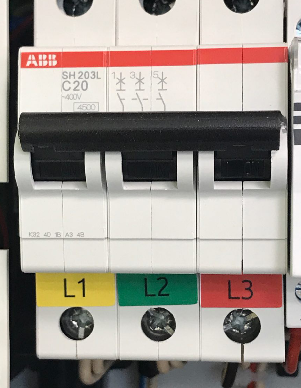
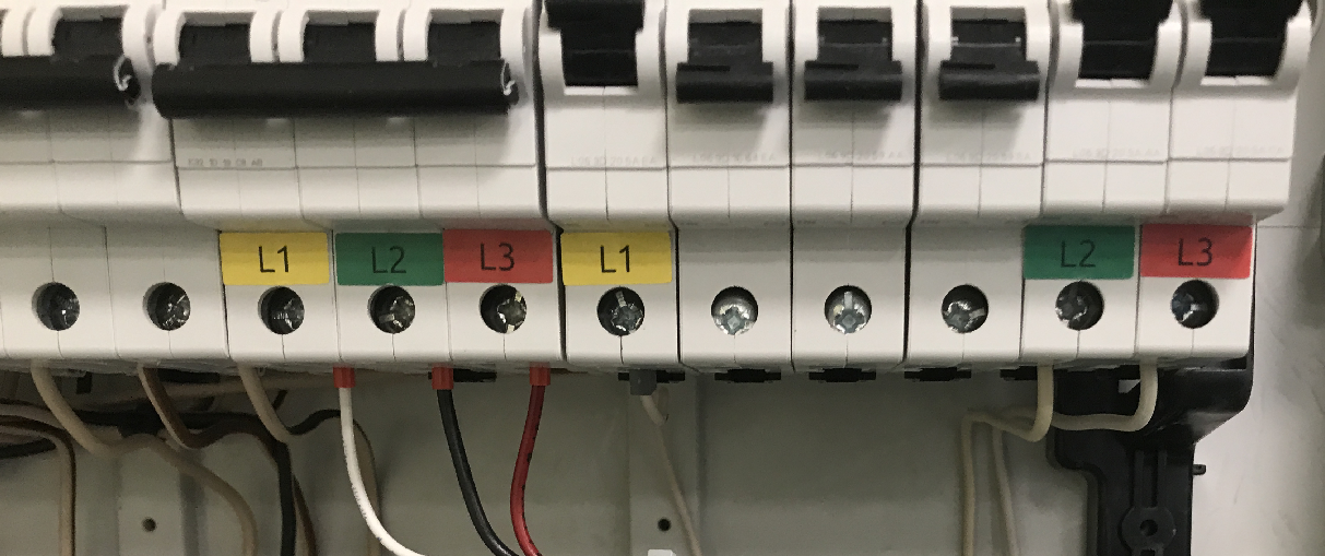
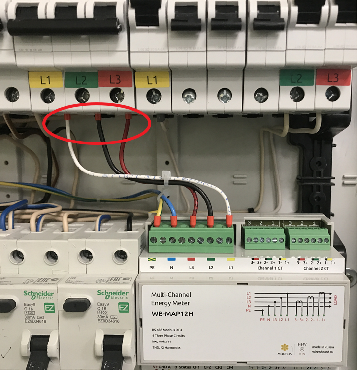
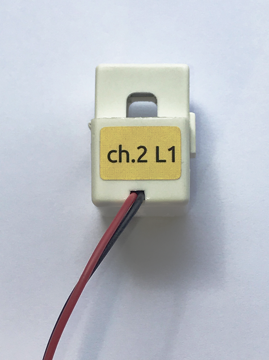
- Mark incoming phases L1, L2 and L3 with the supplied labels.
- Identify the phase of each breaker to be monitored, visually or by continuity testing on an isolated circuit. On an energized panel, a qualified installer can compare voltages: approximately 0 V between the same phase and 400 VAC between different phases.
- Label breakers with phase numbers.
- Use spare breakers, install additional breakers if space permits, or connect through a suitable existing breaker. Do not use breakers serving critical equipment. Two different conductor sizes must not be clamped insecurely in one terminal: use a suitable twin ferrule or compatible terminal accessory.
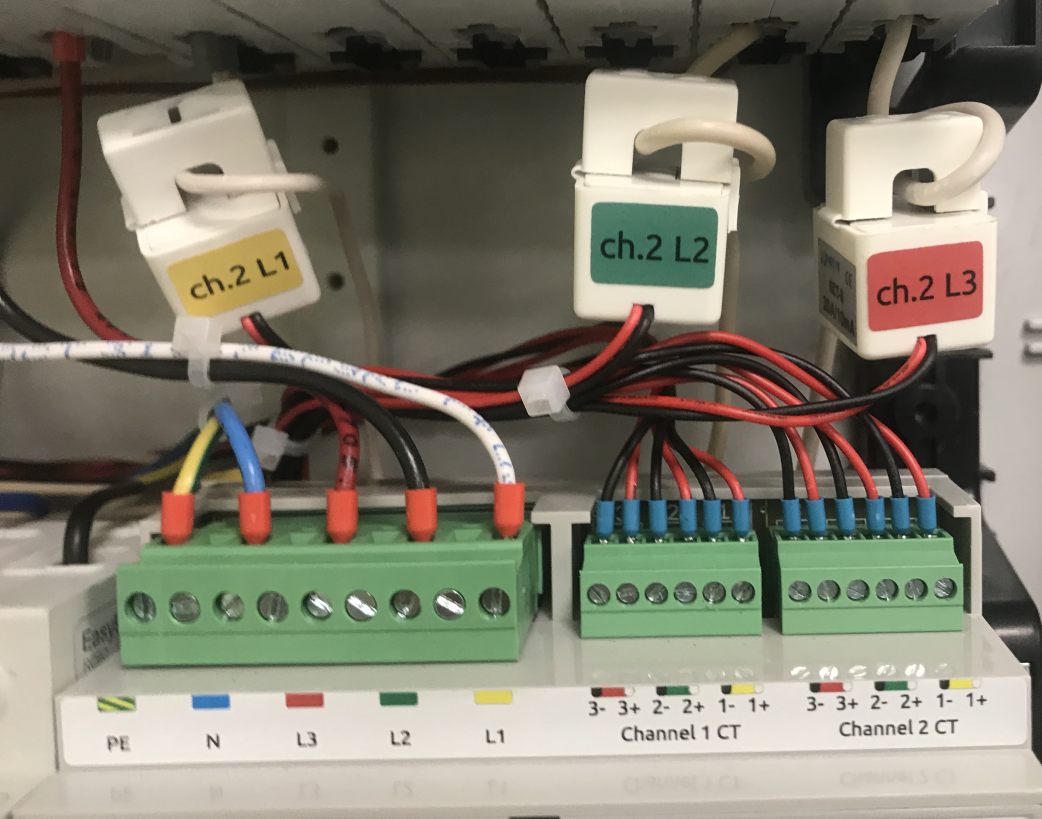
- Label meter voltage wires and breakers, mount the meter on the DIN rail, then connect PE, N and L1/L2/L3 according to the labels.
Current transformers
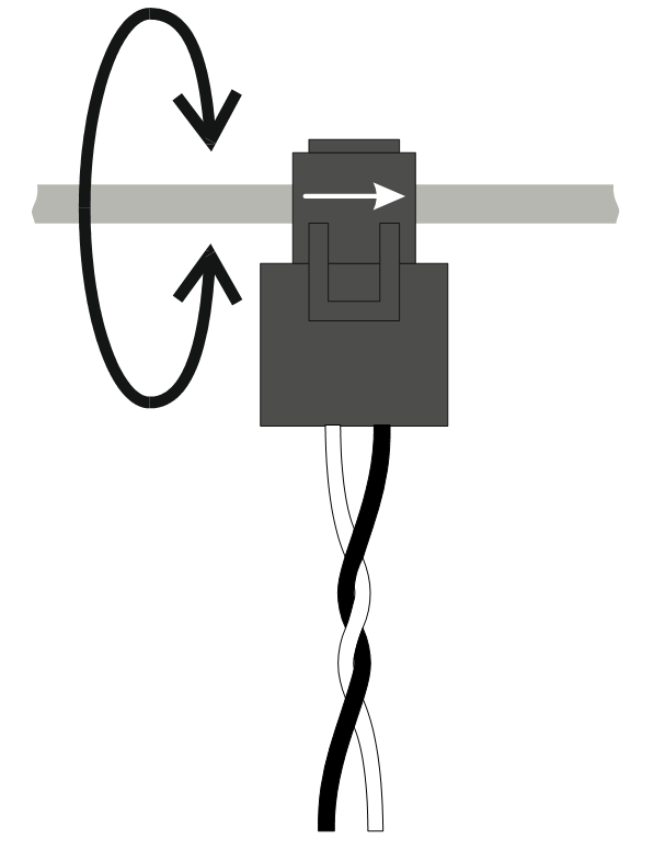
- Fit each transformer around the phase conductor with its arrow pointing toward the load.
- For split-core transformers, clean mating core surfaces with cleaning stickers before closing. The transformer must fit freely without internal pressure or skew; it should rotate freely around the conductor.
- Measure, shorten or extend the leads, then strip the ends. If space permits, retain the original length and secure the excess. Use appropriate ferrules on stranded leads.
- Extensions up to 50 m are permitted only when the total resistance remains below the meter specification. Keep each pair together as twisted pair and insulate joints. The source suggests a suitable 7 × 1.0 mm² cable for three transformers.
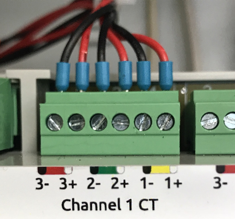
- Connect a three-phase load to one three-phase meter channel, matching 1→L1, 2→L2, 3→L3. Black leads go to minus; coloured leads, such as white or red, go to plus. Preserve assignments when transformer calibration parameters are already stored for particular inputs.
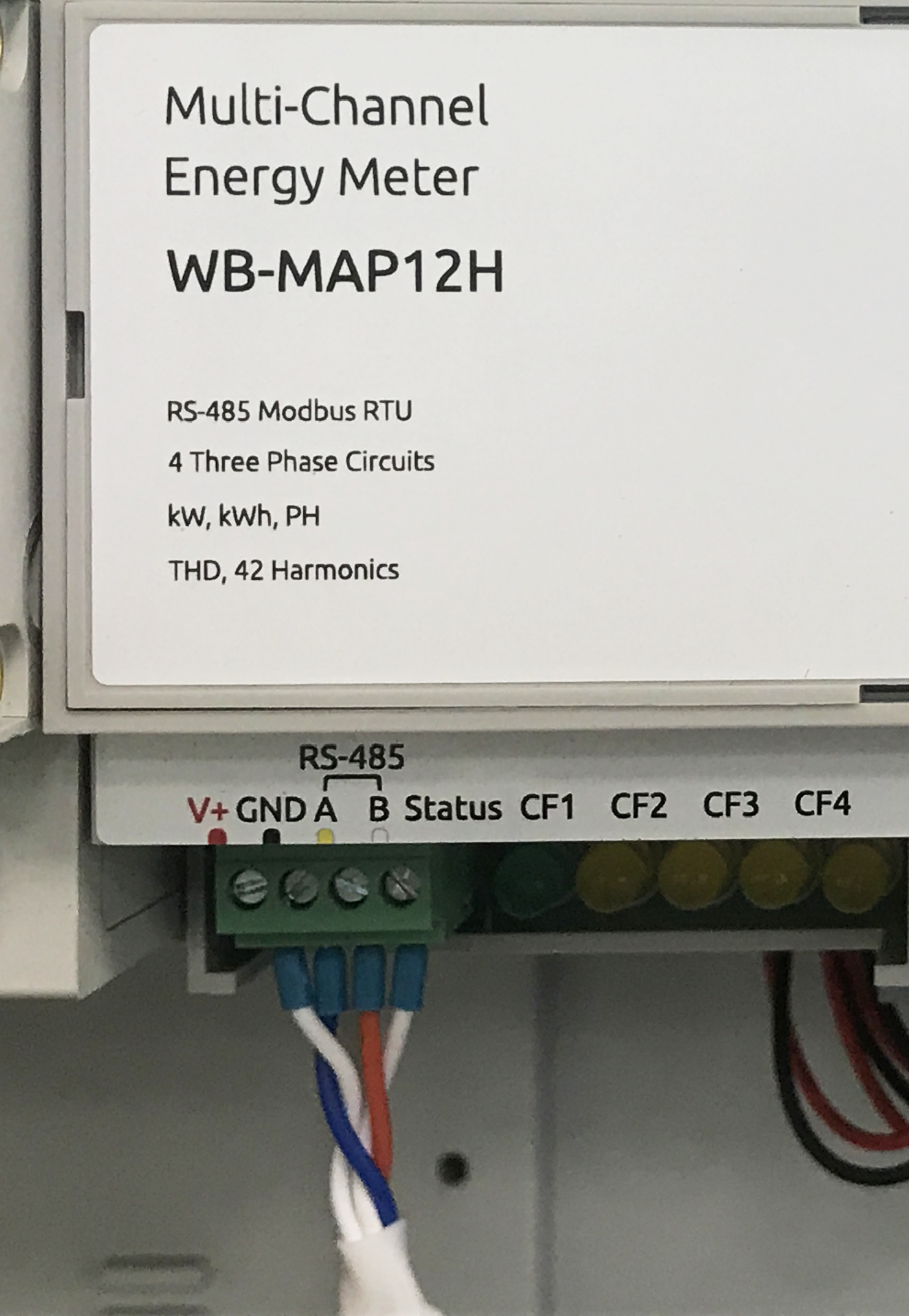
- Connect RS-485 A and B and the common communication ground to GND. Connect V+ where required by the model's interface supply arrangement; follow the WB-MAP3E wiring diagram.
Commissioning
Store the transformer parameters in the meter. Apply a load of approximately 100 W to each phase, then check voltage-to-current phase angles, usually −40° to +40°, and positive active power. See configuration registers.
Indicators
The green Status LED is steady with power and flashes during Modbus communication. CF1…CF4, yellow or red depending on revision, indicate total energy for each three-phase channel. 1000 pulses equal 1 kWh; one pulse per second corresponds to 3.6 kW. The number of indicators depends on the meter model.