Documentation
Wiren Board 8.4
64-bit Linux industrial automation controller
Covered order codes (2)
WB8.4 2 GB / 16 GB— Industrial −40 to +75 °CWB8.4 4 GB / 64 GB— Industrial −40 to +75 °C
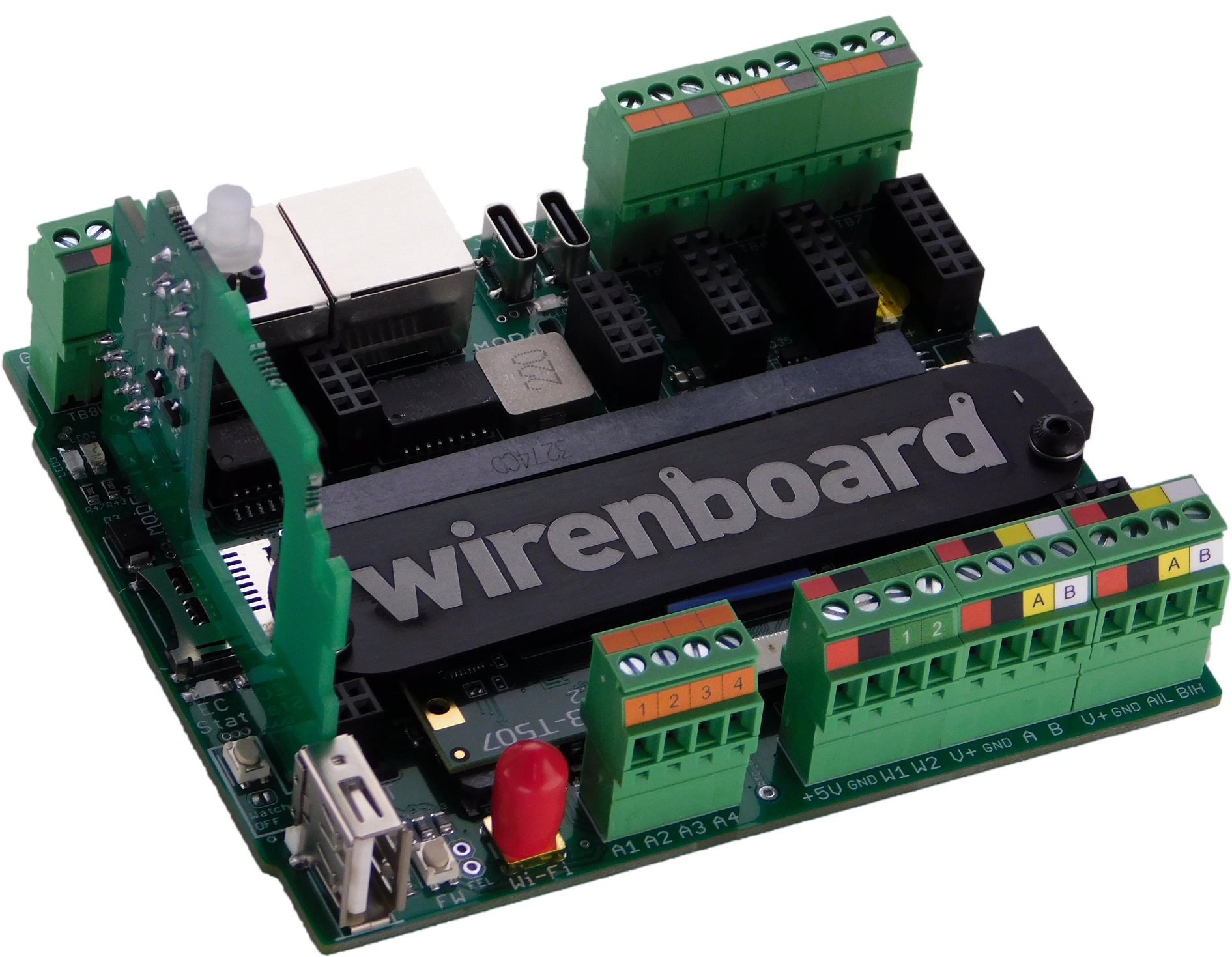
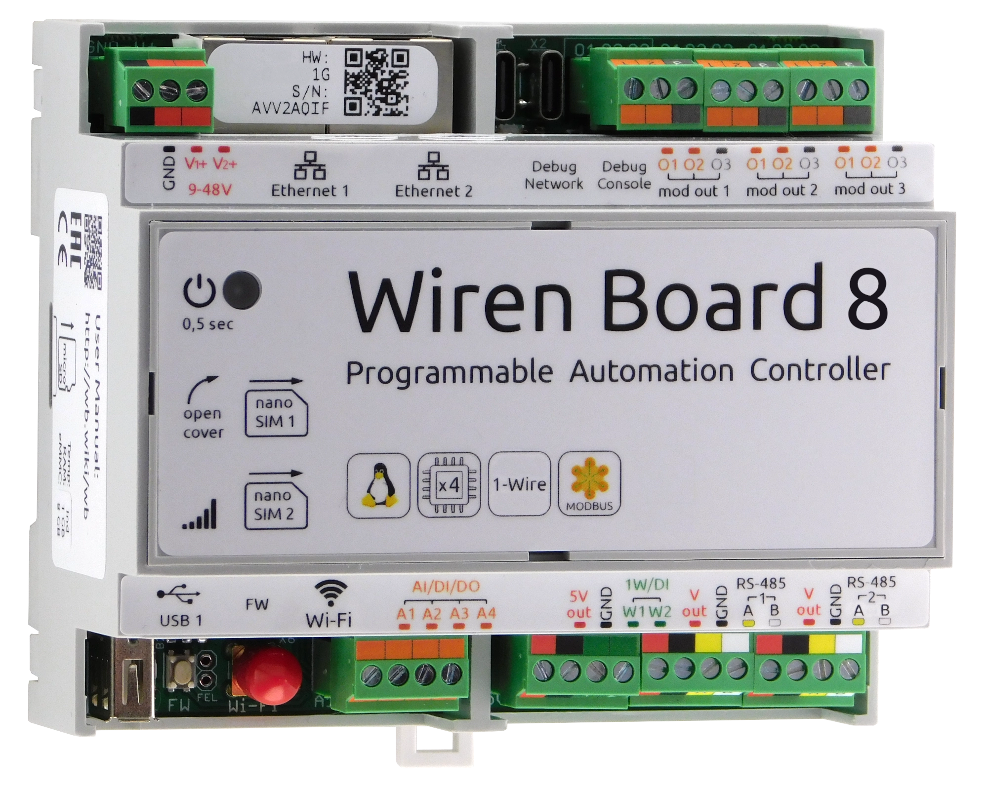
Wiren Board 8.4 is a DIN-rail industrial automation controller with a 64-bit processor. It runs Debian Linux and combines Ethernet, dual-band Wi-Fi, Bluetooth, USB, RS-485, 1-Wire, universal I/O, optional cellular connectivity and internal expansion slots in one programmable controller.
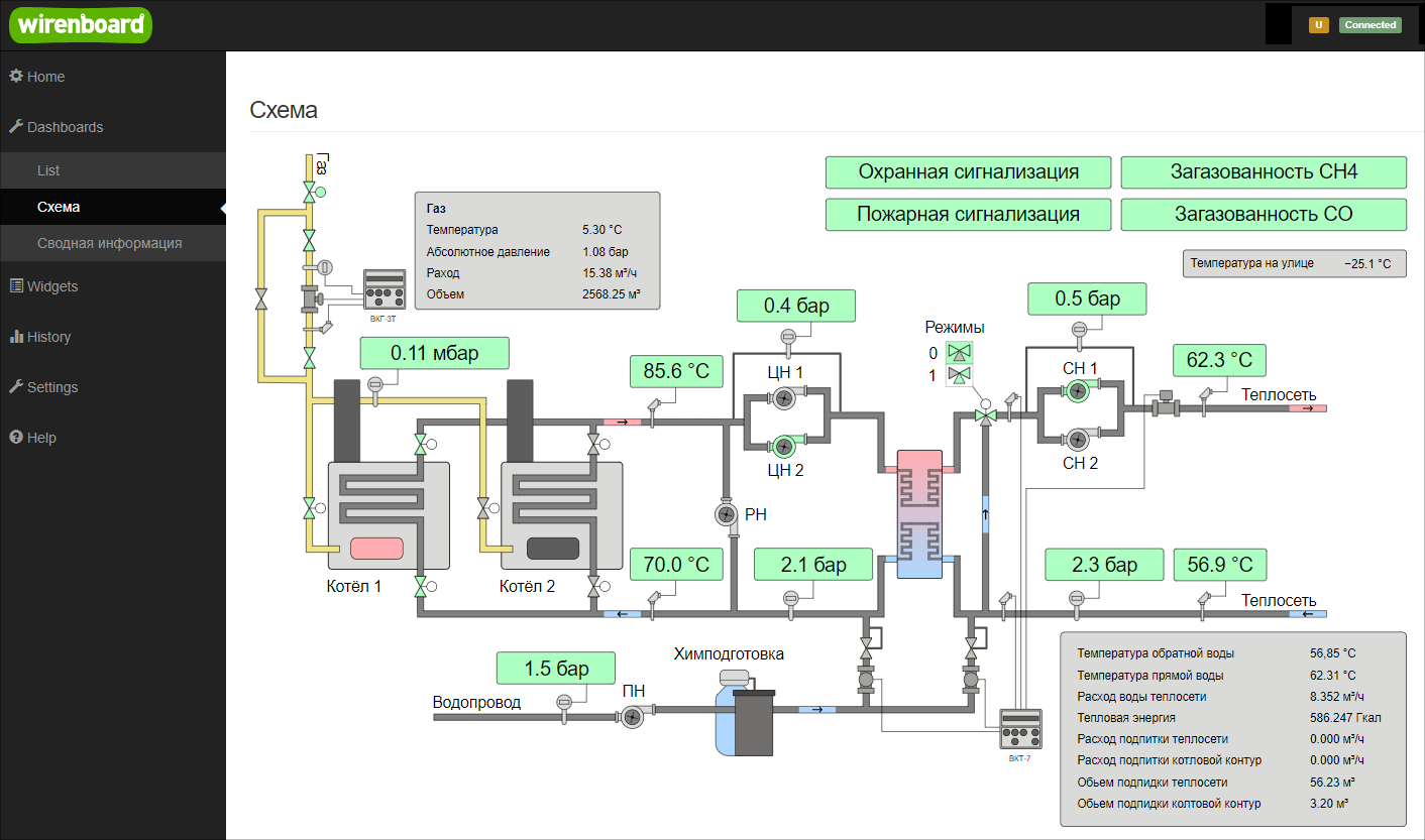
Hardware revision 8.4
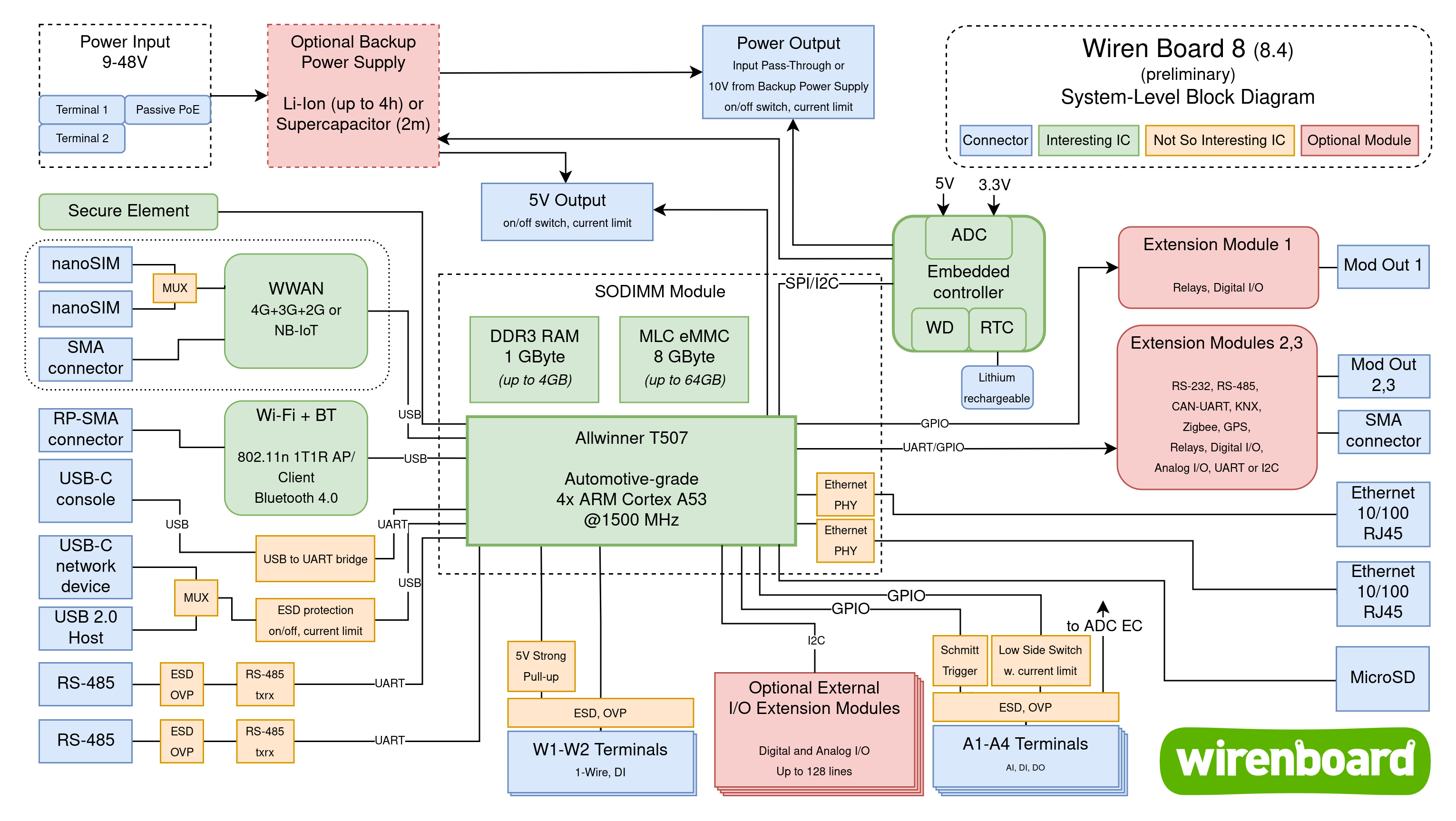
Wiren Board 8.4 is based on the Wiren Board 7.4 baseboard but uses a new processor board:
- 64-bit, four-core ARM Cortex-A53 processor at 1.5 GHz;
- up to 4 GB of LPDDR4 RAM;
- MOD1 accepts only digital input and output modules, while MOD2 and MOD3 accept all compatible modules; MOD4 is unavailable;
- CAN is not fitted in the base configuration, but up to two CAN interfaces can be added with expansion modules;
- Debian Linux 11 uses 64-bit packages, so custom software compiled for earlier controllers must be checked for compatibility.
Technical specifications
| Processor | Allwinner T507, 4-core 64-bit ARM Cortex-A53 at 1.5 GHz |
|---|---|
| RAM | 1 GB, 2 GB or 4 GB LPDDR4, depending on configuration |
| Non-volatile storage | 8 GB, 16 GB or 64 GB eMMC |
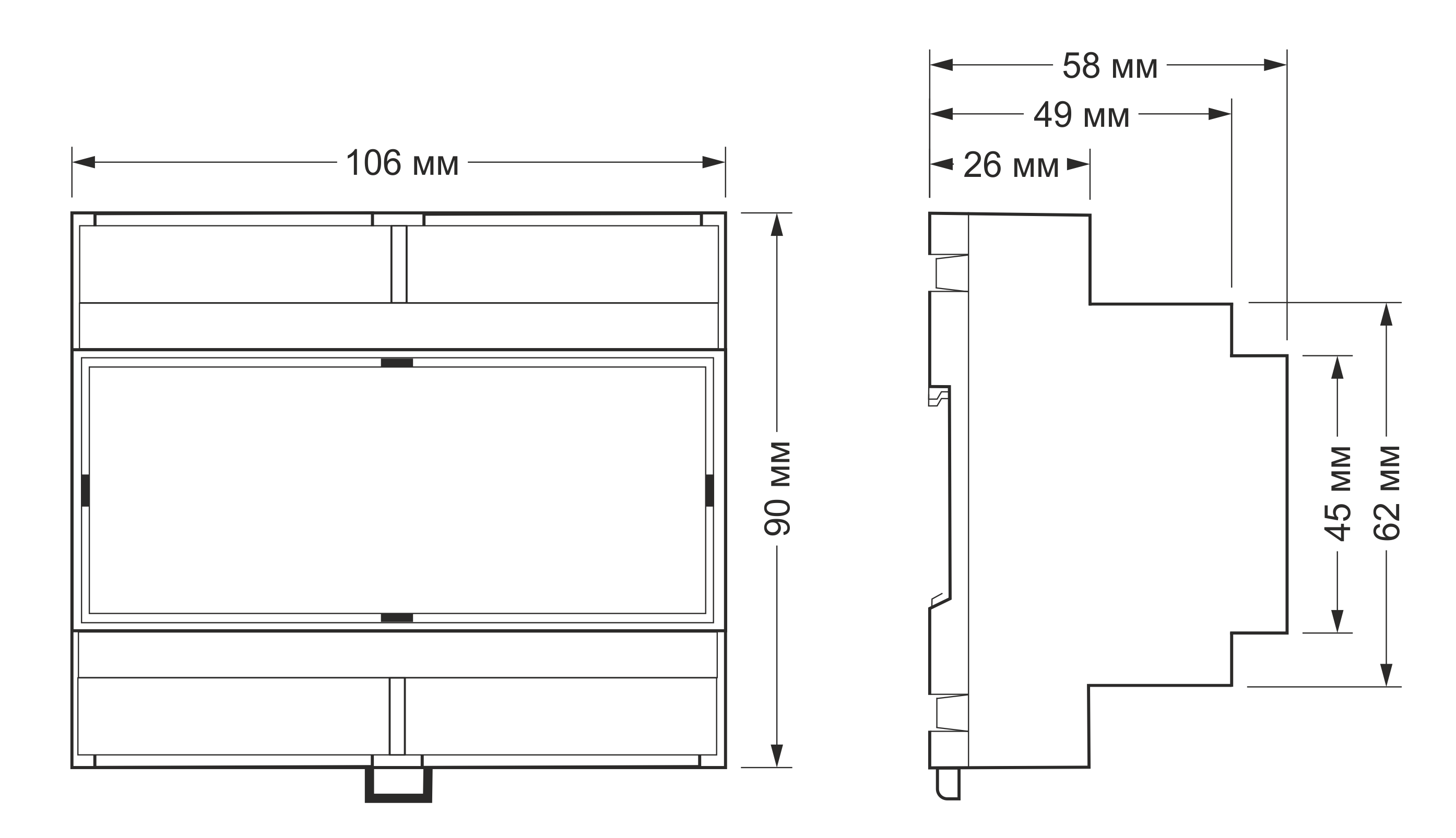
| Dimensions | 106 × 90 × 58 mm; 6 DIN modules |
| Packaged weight | 235 g |
| Operating temperature | Industrial version: −40 to +75 °C; commercial version: 0 to +75 °C |
| Humidity | Up to 92% RH, non-condensing |
| Protection | IP20 |
| Warranty / service life | 2 years / 5 years |
| Interface | Quantity or capability |
|---|---|
| RS-485 | 2 ports; one shares terminals with CAN |
| CAN | Up to 2 interfaces using internal expansion modules |
| MicroSD | 1 slot, up to 50 MB/s |
| W1–W2 | 2 independently configurable 1-Wire / dry-contact input channels |
| A1–A4 | 4 universal digital/analogue inputs and open-collector outputs |
| Ethernet | 2 × 10/100 Mbit/s |
| USB | 1 × USB 2.0 host (Type A), plus USB-C Debug Network |
| Wi-Fi | 802.11a/b/g/n, 2.4 and 5 GHz; access-point and client modes |
| Bluetooth | Bluetooth 4.2 with BLE |
| Cellular | Optional 2G/3G/4G LTE module; two nano-SIM slots, one active at a time |
| Supply | 9–48 V DC |
|---|---|
| Power consumption | About 3 W average; up to 8 W with cellular modem |
| Supply priority | The input with the higher voltage supplies the controller |
| Power inputs | Two V+ terminal inputs; optional 802.3af/at or passive PoE on Ethernet 1 |
| Vout | Controller supply voltage, 1 A total limit, software switching and state retention; automatically disabled above 29 V |
| 5Vout | 5 V sensor supply with current limiting and software switching |
| Expansion | Three internal slots with terminal access; MOD4 is unavailable; side WBIO, backup-power and PoE connectors |
First start
- Screw the Wi-Fi antenna onto its SMA connector.
- If a cellular module is fitted, attach its antenna and insert a nano-SIM card.
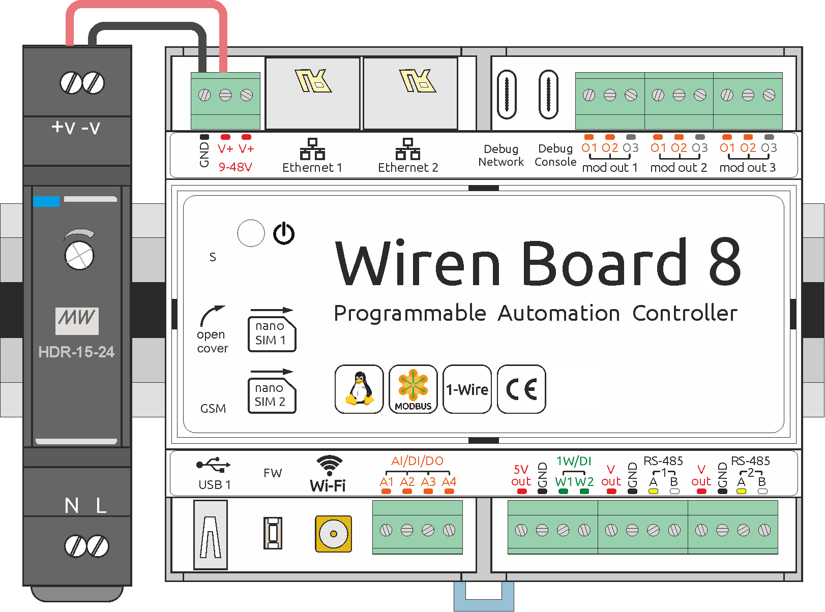
- Connect a 9–48 V DC supply to the terminal block, or use Ethernet 1 if a compatible PoE module is fitted.
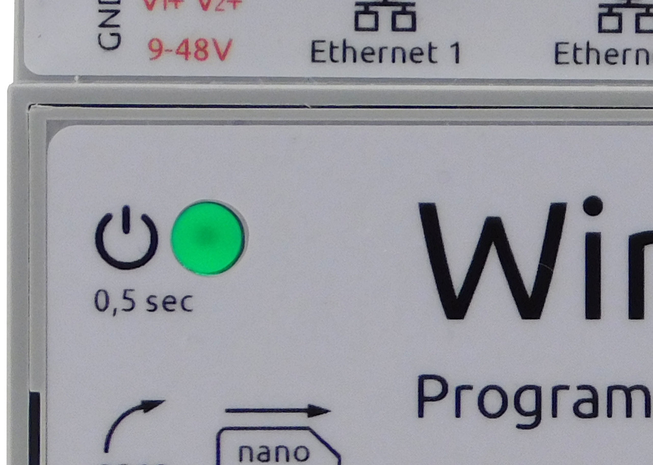
- Wait approximately two minutes for Linux to boot. In normal operation the controller LED flashes green once per second.
A short press of the ON/OFF button, from 0.5 to 10 seconds, requests an orderly Linux shutdown. Holding it for 10 seconds or longer forces power off if the operating system cannot stop normally.
Debug Network
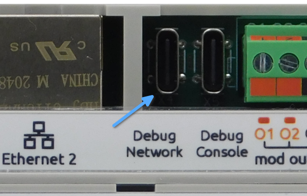
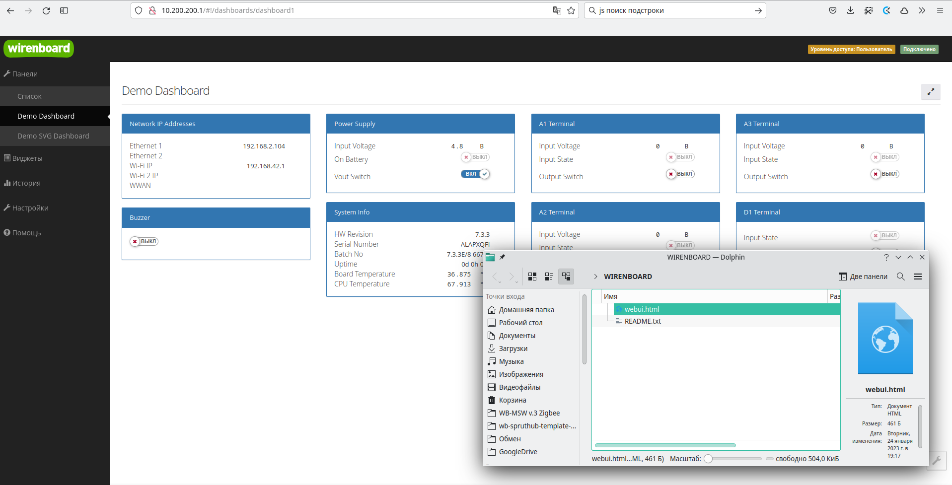
For initial setup on Windows 7 or later and Linux, connect a USB-C cable to Debug Network. The controller appears as a virtual network adapter with a fixed address and exposes both the web interface and command line. macOS and mobile devices should use Wi-Fi or Ethernet instead.
The controller can receive limited power from USB-C during setup, but all side modules and devices powered from Vout, 5Vout or USB must be disconnected. After boot, a virtual drive named WIRENBOARD appears on the computer and contains the web-interface address and a short connection guide.
Wi-Fi and Ethernet
The factory Wi-Fi access point is named WirenBoard-XXXXXXXX, where the final characters are the serial number. It is initially open and the controller address is 192.168.42.1. Both Ethernet ports request an address by DHCP. Connect either port to a router, find the assigned address in the router interface, then open it in a browser.
Web interface and command line
The built-in web interface configures the controller and connected devices, edits automation rules, manages notifications, displays historical charts and provides text or graphical operator dashboards. Linux configuration files and advanced tools are available over SSH or the Debug Console. The factory command-line credentials are root / wirenboard.
Secure the controller immediately
- Set a Wi-Fi password or disable the access point.
- Change the root password and preferably use SSH keys.
- Create web-interface users with the minimum required access level.
- Protect the MQTT broker with authentication.
- Use a managed remote-access service or VPN. Before assigning a public IP address, have an administrator enable HTTPS and restrict exposed ports.
- Update controller firmware and set the correct time zone.
Software
The controller runs Debian Linux. Standard packages can be installed with apt install package-name. Wiren Board distributes a stable release for production systems and a rolling testing release for commissioning and early access to new packages.
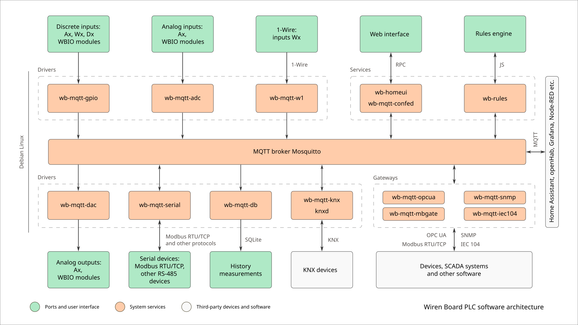
The preinstalled MQTT broker is the central message bus. The web interface configures devices, controls channels, displays data and edits rules. wb-rules provides JavaScript-like automation, while wb-scenarios handles common lighting and heating tasks without programming.
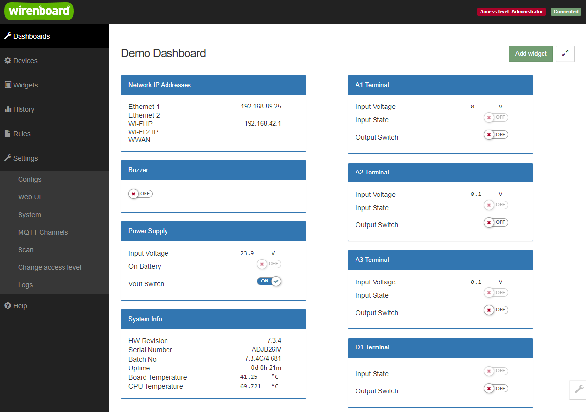
Supported integration options include Modbus RTU/TCP master and slave, MQTT, OPC UA, SNMP, IEC 60870-5-104, Zabbix, KNX, eBUS, OpenTherm, DLMS/COSEM, 1-Wire, DALI through a gateway, Zigbee and Z-Wave through radio modules. Common software includes Node-RED, Grafana, Home Assistant, IntraSCADA, Rapid SCADA and Docker. Applications can be written in Python, C++, Go, Node.js or IEC 61131-3 environments.
Boot status indicator
Hardware with a separate two-colour LED can display green, red or orange. Hardware with the LED built into the button alternates red and green. The indicator provides a quick boot diagnostic:
| Time or condition | Separate LED | Button LED | State |
|---|---|---|---|
| Power applied | Off | Off | The embedded controller prepares power-up |
| About 0.2 s | Orange | Red | U-Boot waits three seconds for Debug UART input |
| About 5 s with update USB drive | Flashing orange | Flashing red | Firmware file detected; U-Boot waits for confirmation |
| About 5 s without update media | Red | Red | Hardware configuration is being applied |
| About 10 s | Flashing red | Flashing red | Linux and internal services are loading |
| About 60–70 s | Flashing green | Flashing green | Operating system ready |
Internal and side expansion modules
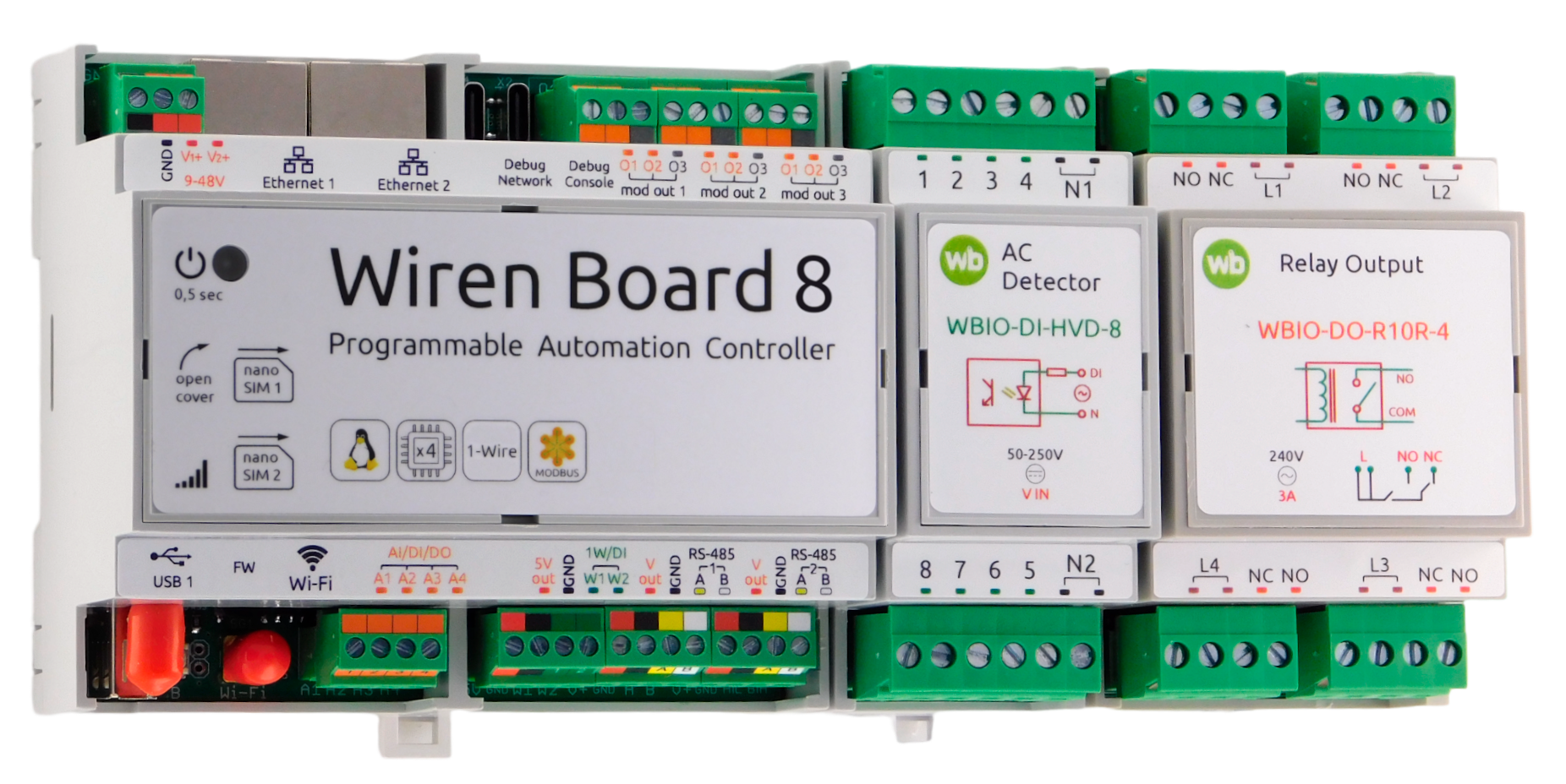
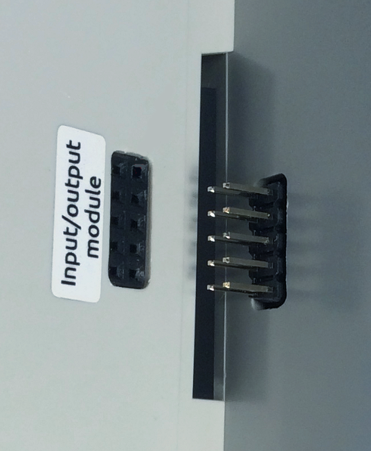
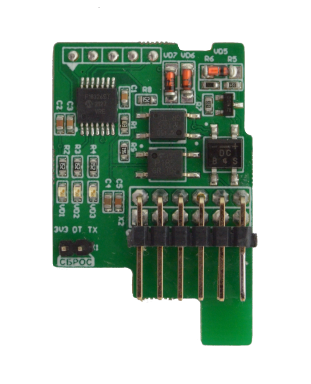
Four internal slots accept compact expansion boards for RS-485, RS-232, relay outputs and other interfaces. Three slots have three external terminals each. WBIO side modules attach to the right-side connector and add 8–16 digital or analogue ports. Up to eight side modules may be connected in sequence: up to four input modules and four output or combined I/O modules. Optional mezzanine boards provide backup power or PoE.
Wireless interfaces
Dual-band 2.4/5 GHz Wi-Fi can operate as an access point, a client, or both simultaneously. Bluetooth 4.2 Low Energy can detect nearby phones or beacons.
Z-Wave and Zigbee support can be added with compatible radio modules. Cellular modules provide 2G, 3G or 4G LTE, SMS and Internet access; two SIM slots are multiplexed so only one SIM is registered at a time. Connect Wi-Fi, cellular and radio antennas to their SMA connectors. If cellular reception is weak, use a remote antenna positioned away from the controller.
Wired interfaces
The two 10/100 Ethernet ports use DHCP by default. The USB-A connector is a USB 2.0 host and can also be used for firmware installation. Connecting Debug Network disables USB 1.
Two RS-485 ports are built in; additional isolated RS-485 ports and up to two CAN interfaces can be added with expansion modules. The standard wb-mqtt-serial driver connects RS-485 devices to MQTT.
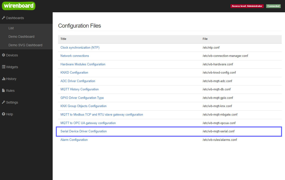
The Debug Console is the recovery interface for bootloader messages and shell access. Debug Network provides web and console access over USB-C and can install firmware or perform a factory reset.
MicroSD storage
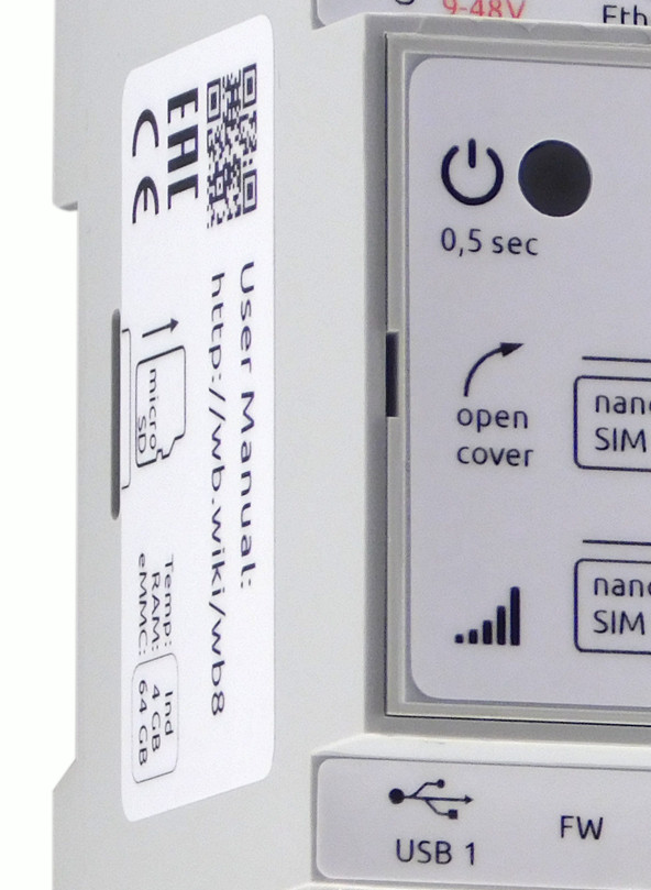
The high-speed MicroSD slot is on the left side. Insert the card contacts-down until it clicks. It can store backups and logs or extend available data storage. The card appears as /dev/mmcblk1; its first partition is mounted automatically at /mnt/sdcard.
Universal I/O A1–A4
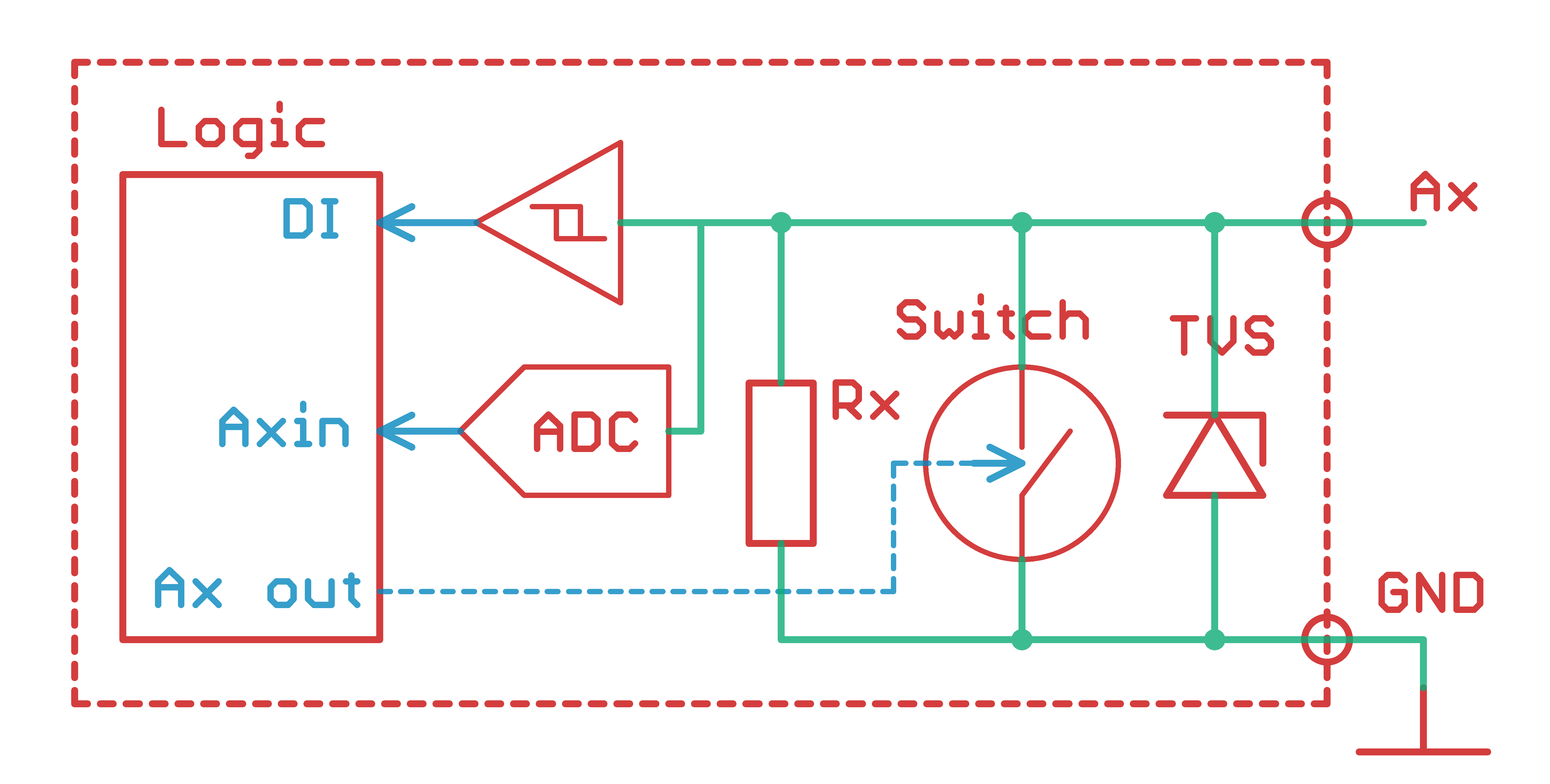
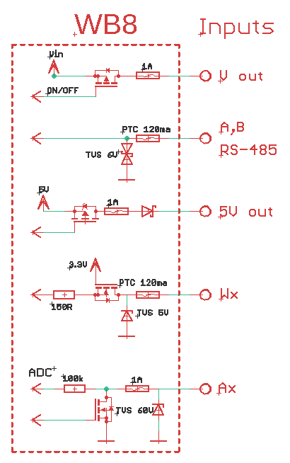
Each channel has a 100 kΩ input resistance. Digital and analogue input measurements operate simultaneously while the output switch is off. Setting Ax_OUT on connects the terminal to GND through the open-collector output.
| Function | Electrical characteristics | MQTT control |
|---|---|---|
| Open-collector output | Up to 1 A at 30 V; sinks to GND | wb-gpio/Ax_OUT |
| Digital input | Logic 1 above 3 V, logic 0 below 1.5 V. | wb-gpio/Ax_IN |
| Analogue input | 0–36.3 V, ±(1% + 60 mV). | wb-adc/Ax |
W1–W2 channels
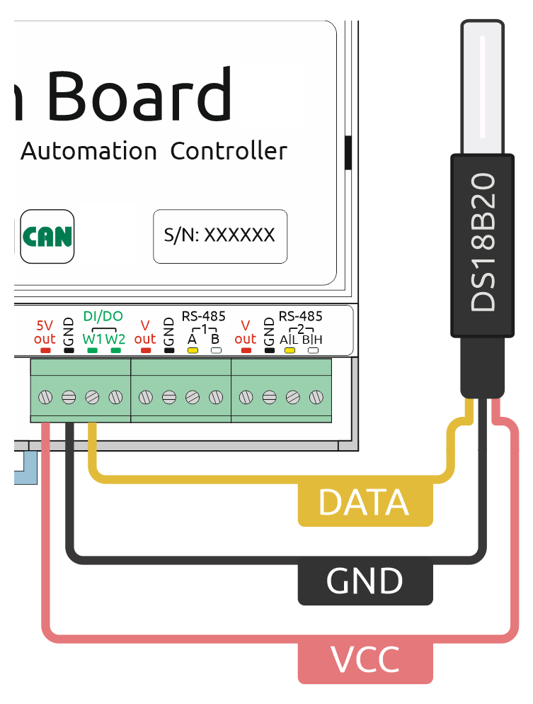
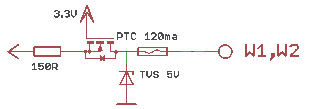
W1 and W2 are independently configurable as 1-Wire interfaces or dry-contact digital inputs. Select the mode in the web interface under Settings → Configs → Expansion modules and ports → Wx terminal mode.
In 1-Wire mode an internal 3 kΩ pull-up is already fitted, so no external resistor is required. Supported temperature sensors include DS18B20. Bus length, topology and cable quality determine the reliable number of sensors. In digital-input mode, the channel activates when shorted to GND.
5Vout and Vout power outputs
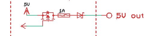
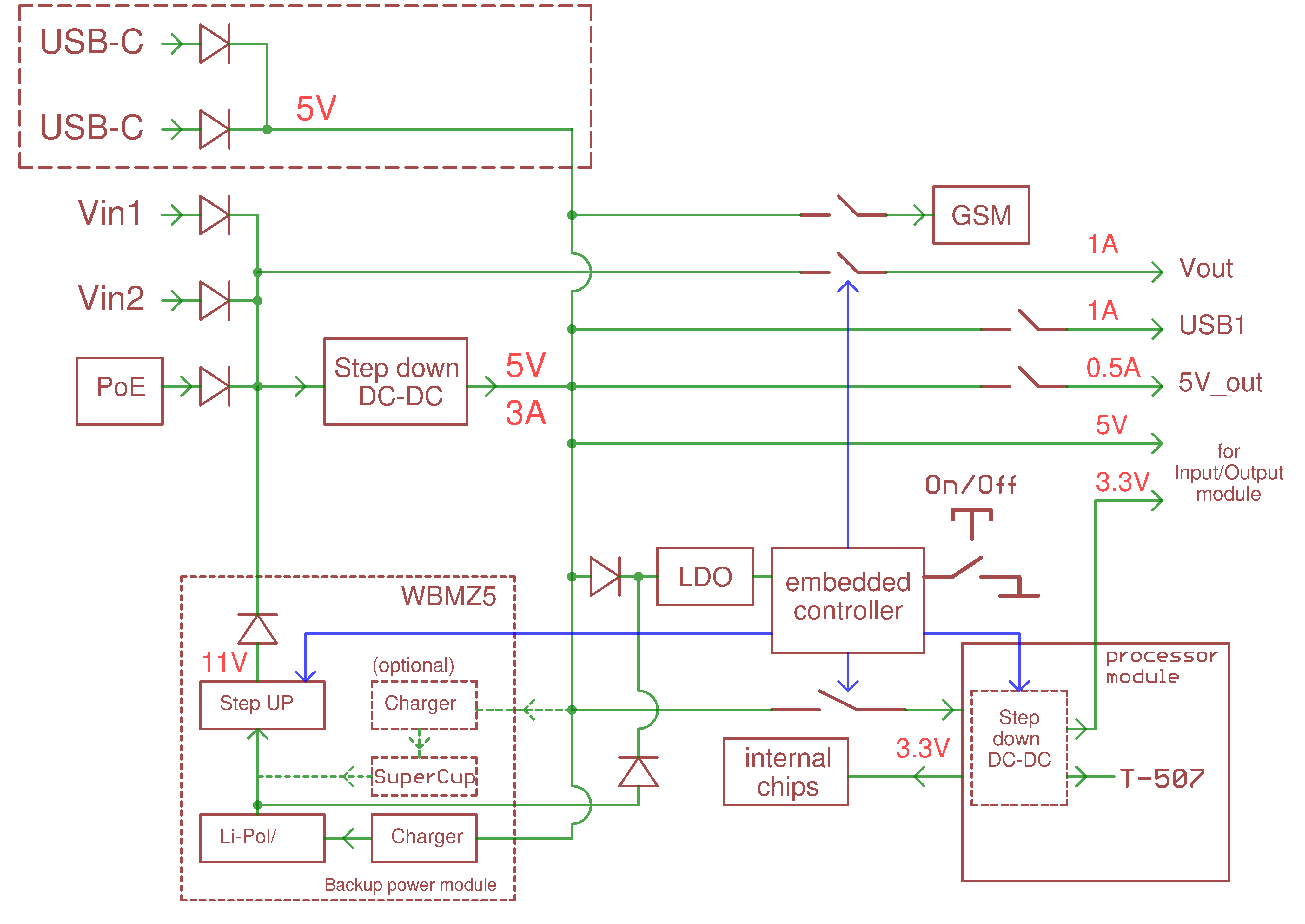
5Vout supplies 5 V for sensors and is protected against short circuit and external overvoltage. It remains active on backup power and can be switched from the 5V_OUT channel of the Discrete I/O device.
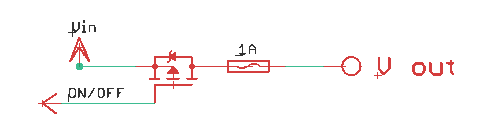
The two Vout terminals carry controller supply voltage with a combined 1 A limit. Their software state is retained across restart and power-button shutdown. Vout switches off automatically above a 29 V controller supply; on backup power it provides 11 V. Control it with Relays & FETs → V_OUT. A self-resetting 1 A polyfuse protects the output.
RS-485 termination and failsafe bias
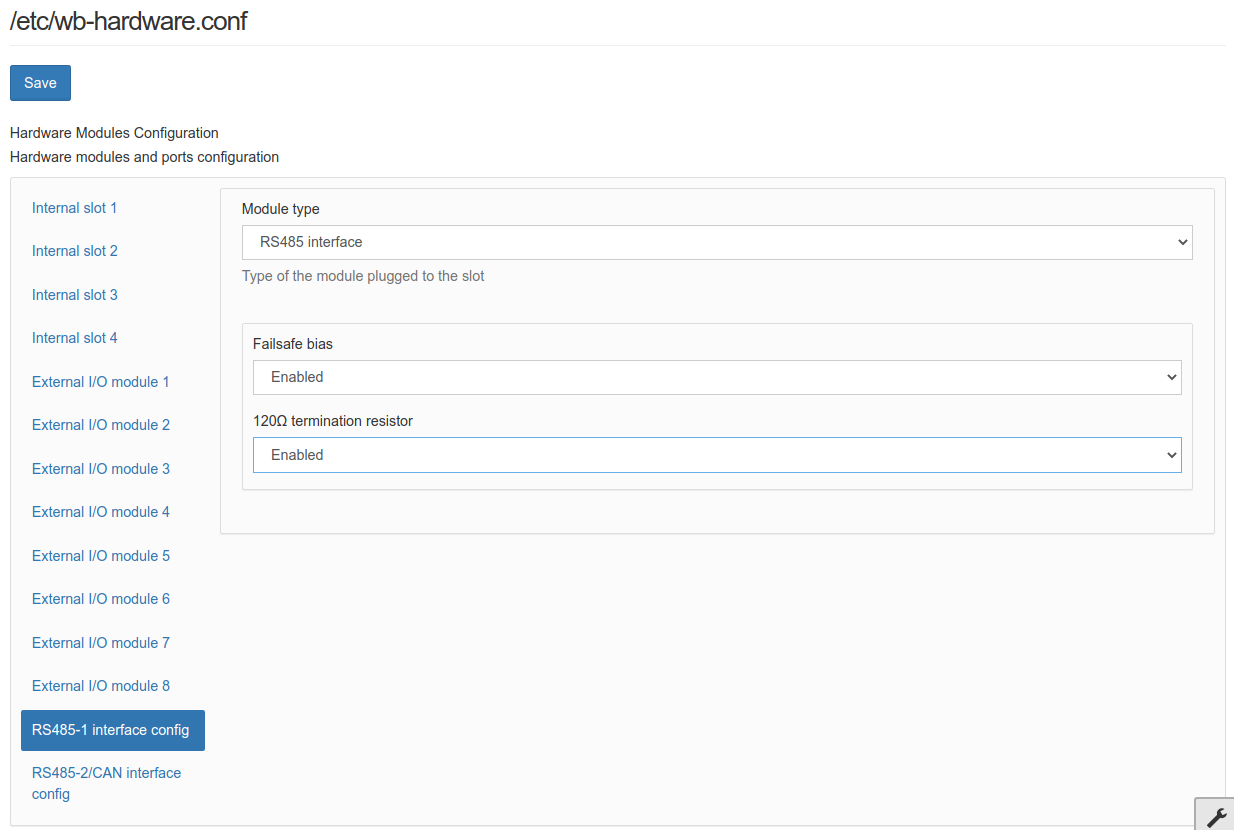
An RS-485 line must be terminated with 100–120 Ω at both physical ends. The controller has software-controlled terminators. Failsafe bias resistors on A and B are enabled by default; disable them in the web interface when the controller operates as an RS-485 slave.
Terminal blocks and wiring
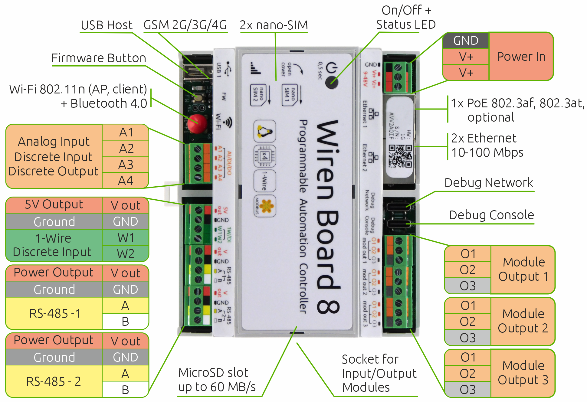
| Terminal | Limit | Function |
|---|---|---|
| Vin / GND | 52 V maximum | Power input with reverse-polarity protection; all GND terminals are common |
| O1–O3 | Module dependent | Internal expansion-module I/O |
| A1–A4 | 30 V, 1 A | Open-collector output, digital input and ADC |
| W1–W2 | 5 V | 1-Wire or GPIO/dry-contact input |
| 5Vout | 5 V, 0.5 A | Software-switchable sensor supply |
| A / B | 5 V interface | RS-485 port 1 |
| RS-485-2 A / B | 5 V interface | Second built-in RS-485 port |
| Vout | 1 A total | Software-switchable controller supply output, protected above 29 V |
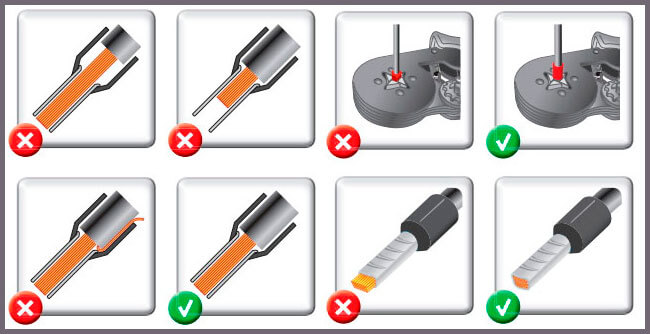
Use flexible stranded conductors with insulated wire-end ferrules. For control terminals use 0.35–1 mm² single ferrules or 0.35–0.5 mm² twin ferrules; torque is 0.2 N·m. Power terminals accept up to 2.5 mm² single or 1.5 mm² twin ferrules; torque is 0.5 N·m. The recommended ferrule sleeve length is 8 mm. Do not overtighten the removable 3.5 mm-pitch screw terminals.
A software-controlled buzzer is also built into the controller.
Power and backup power
Connect one or two 9–48 V DC power supplies to V+ with common GND. When several inputs are present, the source with the higher voltage is used. Ethernet 1 can receive IEEE 802.3af/at PoE through WBP-ACTIVE-POE, passive PoE above 42 V through that module, or lower-voltage passive PoE through WBP-PASSIVE-POE.
WBMZ5-BATTERY or WBMZ4-SUPERCAP provide backup power. When Vin falls below 11 V, the module supplies 11 V to the controller and Vout-connected loads. USB-C can power the controller for recovery or setup only; disconnect external devices and WBIO modules because USB power is limited.
Embedded controller, scheduled wake-up and watchdog
The embedded microcontroller manages power, the real-time clock, A1–A4 voltage measurement, board temperature, scheduled wake-up and the watchdog timer.
To shut down now and wake after 60 seconds:
rtcwake -m off -s 60To wake at an absolute local time, convert it to Unix time and pass the result to rtcwake:
date +%s -d "2026-10-09 07:15"
rtcwake -m off -l -t 1791522900
Verify the generated timestamp for the controller time zone before using it. Scheduled wake-up can also be automated through wb-rules.
The hardware watchdog reboots the controller if monitored software stops responding. Stop the watchdog before changing configuration of monitored services, validate the changes, then start it again. If an invalid configuration causes a reboot loop, connect over SSH during the first 60 seconds after boot and stop the watchdog service.
Remote operation and troubleshooting
For remote sites, use a managed remote-access service, Tailscale or a properly administered VPN. Keep date, time and time zone correct for logs, certificates and scheduled rules. The hardware batch number is printed on the enclosure label and PCB and combines the baseboard and processor-board batch numbers.
Relays and contactors can generate high-frequency transients of several kilovolts, especially with inductive loads. Fit the appropriate RC snubber, varistor or other suppression device directly at the load or switching element, route power and communication wiring separately, and use correct RS-485 topology and termination.
Board and dimensions