Documentation
WB-MSW-ZIGBEE v.4
Hybrid wall-mounted Zigbee climate and multisensor
Covered order codes (1)
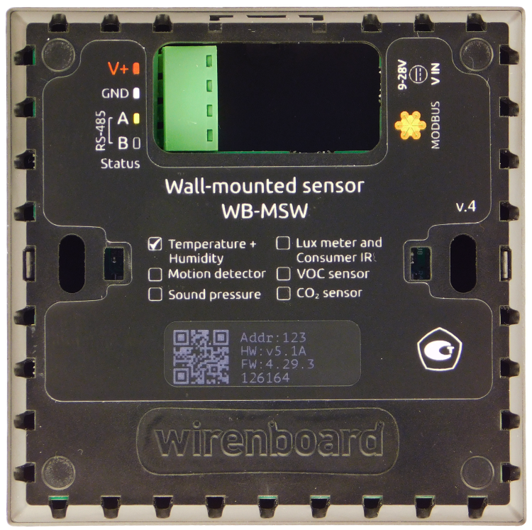
WB-MSW-ZIGBEE v.4— Selectable sensor configurations
The WB-MSW-ZIGBEE v.4 is a wall-mounted indoor multisensor for homes and offices. Depending on the ordered configuration, it measures temperature, relative humidity, carbon dioxide, volatile organic compounds (VOC), illuminance, motion and sound level. It also includes an infrared transceiver for controlling air conditioners and other equipment. The device can communicate wirelessly over Zigbee or operate as a wired RS-485 Modbus RTU sensor.
Models and enclosure options
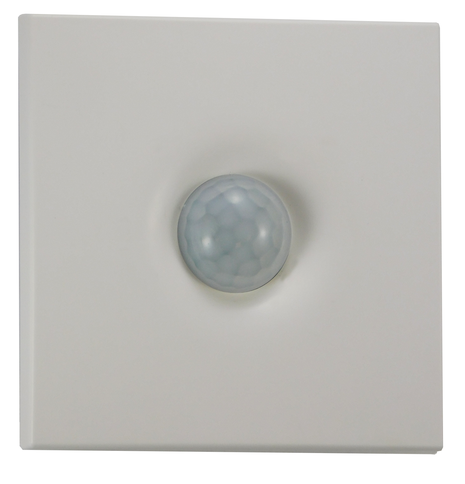
CO₂ and VOC sensors are optional and must be selected when ordering. If an optional sensor is not fitted, the corresponding value is reported as zero or unavailable. The standard enclosure is white; black and mixed-colour enclosures are also available.
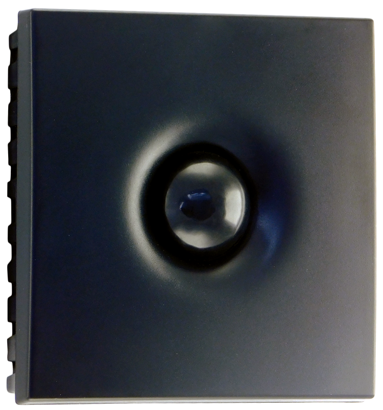
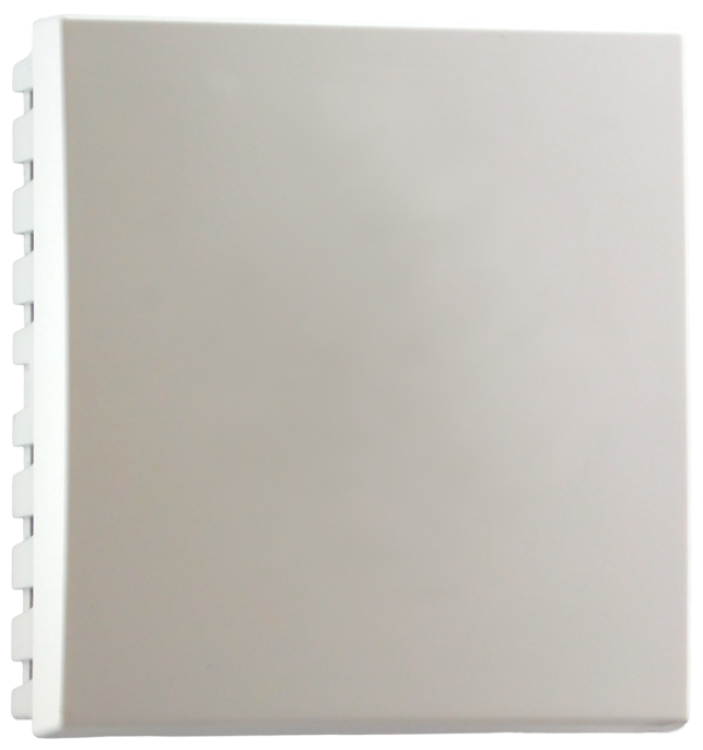
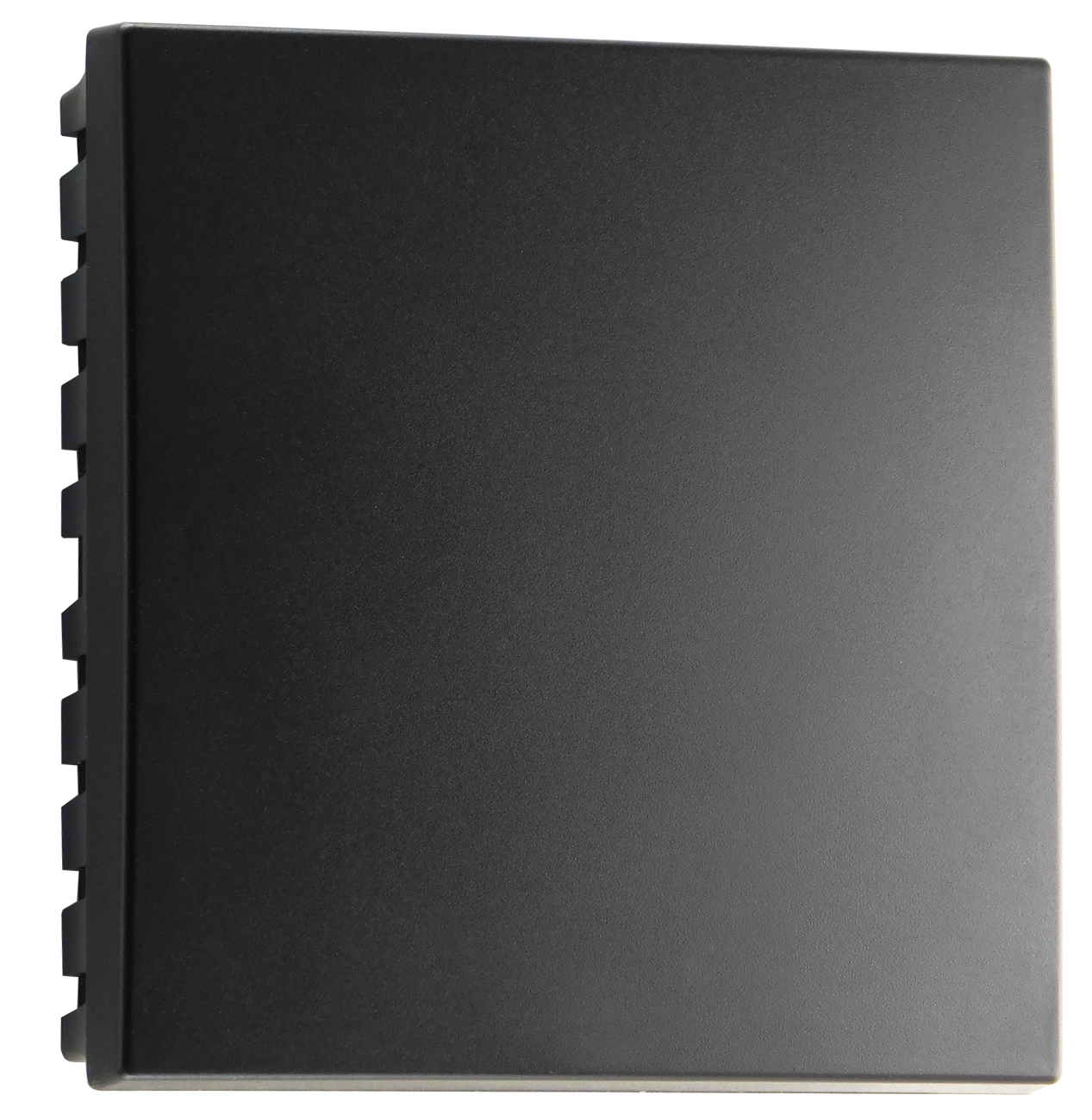
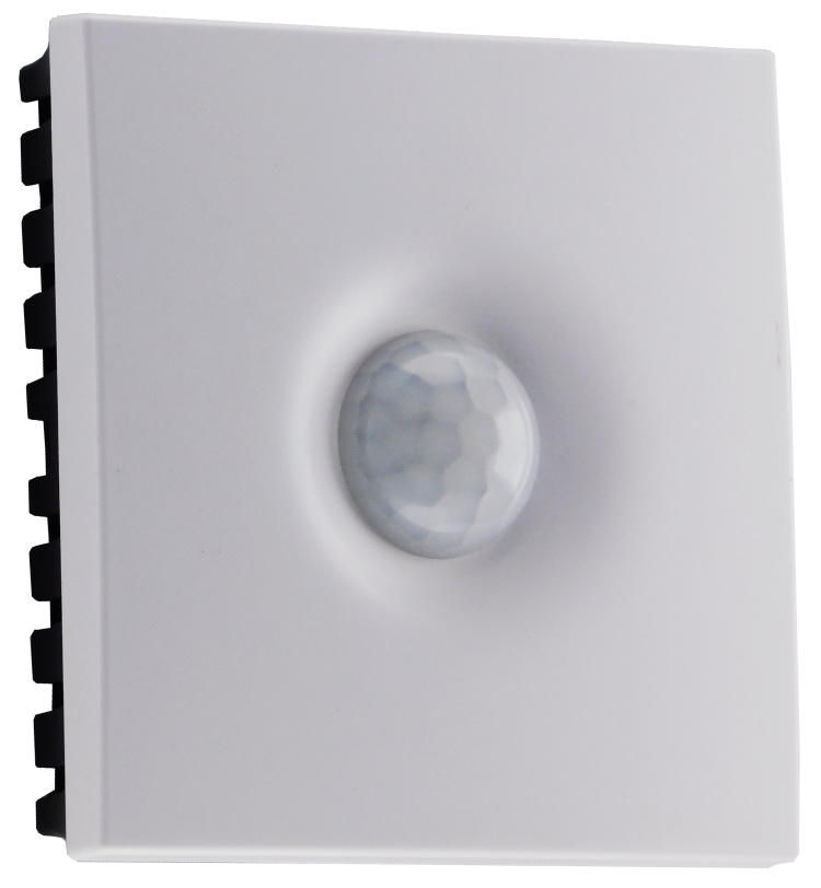
A black lens reduces the illuminance reading by approximately five to seven times and shortens the useful infrared range by about 2.5 to 3 times, typically to 3–4 m. Indicator LEDs are also much dimmer through the black lens. A flat cover can be ordered where motion detection, infrared control, LEDs and illuminance measurement are not required. The enclosure may be repainted; keep all sensor openings and the lens clear.
Technical specifications
| Measurement | Range | Accuracy or response | Notes |
|---|---|---|---|
| CO₂ | 400–10,000 ppm | ±100 ppm + 5% of reading | Ready in about 3 minutes; automatic baseline calibration every 7 days |
| Temperature | −40 to +80 °C | ±0.3 °C from 0 to +70 °C; ±0.5 °C outside this range | 1 s sensor time constant; enclosure reaches equilibrium in about 4 minutes |
| Relative humidity | 5–95% RH | ±3% RH at ambient temperature ≥0 °C | 1 s sensor time constant |
| Sound level | 39–90 dBA | ±2 dB; 5 s response | A-weighted level |
| Illuminance | 0–145,000 lx | ±10%; up to 1.5 s response | Spectral response approximates the human eye |
| VOC | 0–60,000 ppb ethanol equivalent | ±15% typical, ±40% maximum | Initial readiness depends on the fitted sensor; see the VOC section |
| Motion | Up to 8 m, 120° | Ready about 8 s after power-up | Passive infrared detector |
| IR transceiver | Up to 10 m with clear lens | Ready about 1 s after power-up | Stores up to 80 commands; maximum 1,000 pulse symbols per command |
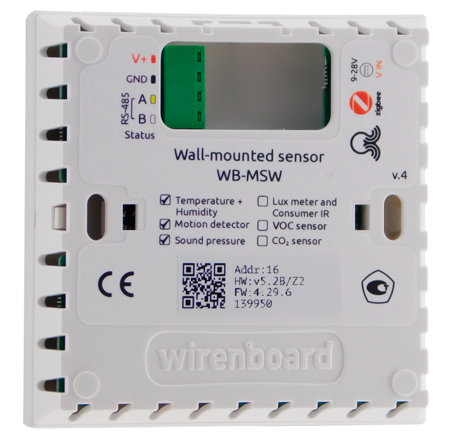
| Supply voltage | 9–28 V DC |
|---|---|
| Power consumption | 0.5 W typical; up to 1.6 W with CO₂ measurement; up to 4 W during simultaneous CO₂ measurement and IR transmission |
| Interfaces | Zigbee; RS-485 with Modbus RTU |
| Controls and indicators | Red and green user LEDs, status LED and buzzer |
| Start-up time | Approximately 2 s, excluding individual sensor warm-up |
| Operating conditions | −40 to +80 °C, up to 95% RH without condensation. With a CO₂ sensor fitted: −10 to +50 °C |
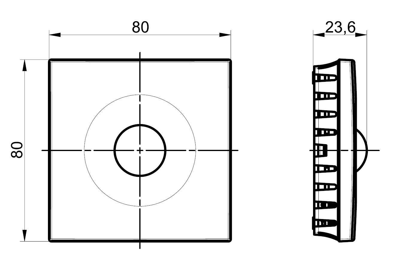
| Dimensions | 80 × 80 × 23.6 mm with lens; 60 mm mounting-hole spacing; compatible with a 68 mm round European wall box |
| Packaged weight | Approximately 90 g |
| Service life / warranty | 8 years / 2 years |
For screw terminals, use single insulated wire-end ferrules for 0.35–1 mm² conductors or twin ferrules for 0.35–0.5 mm² conductors. The recommended sleeve length is 8 mm and the tightening torque is 0.2 N·m. Size the cable and power supply for voltage drop and peak consumption.
Sensor operation
Temperature and humidity
The SHT40 sensor includes automatic compensation for heat generated inside the enclosure. The standard corrections are 0.30 °C for the main electronics, 0.31 °C for the CO₂ module and 0.14 °C for the VOC module. Raw uncompensated temperature and humidity are available in Modbus registers 284 and 285; a user temperature offset is available in register 245.
At relative humidity above 95%, the anti-condensation heater switches on automatically for one second. It can be controlled manually with coil register 2. A separate cleaning mode heats the sensing element to about 110 °C for one hour and temporarily suspends normal measurements other than raw temperature and humidity. Run cleaning only at an ambient temperature of 15–40 °C, never above 50 °C, and only when necessary because heater life is limited. Start cleaning from the controller interface or with coil register 8; holding register 365 reports the remaining time in seconds.
Motion detection
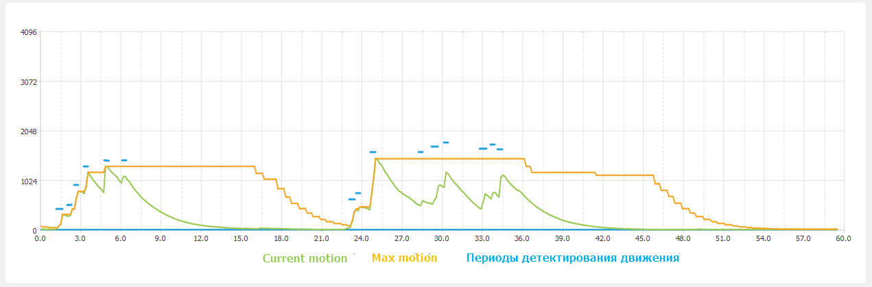
Current Motion is a short moving average and is suitable for fast polling. Max Motion keeps the maximum value over a configurable period, 10 seconds by default in register 282, and is suitable for slower polling. The sensitivity threshold can be raised to reduce triggers from pets. Firmware 4.37 and later also allows the input RC-filter time constant to be adjusted. Fast Modbus events can be used for immediate wired notifications.
Indicators and buzzer
The red and green user LEDs can be flashed under automation control; the buzzer is available in every configuration. User LEDs require the lens board used by the illuminance and IR options. A separate green status LED indicates data exchange and can be disabled.
Infrared transceiver
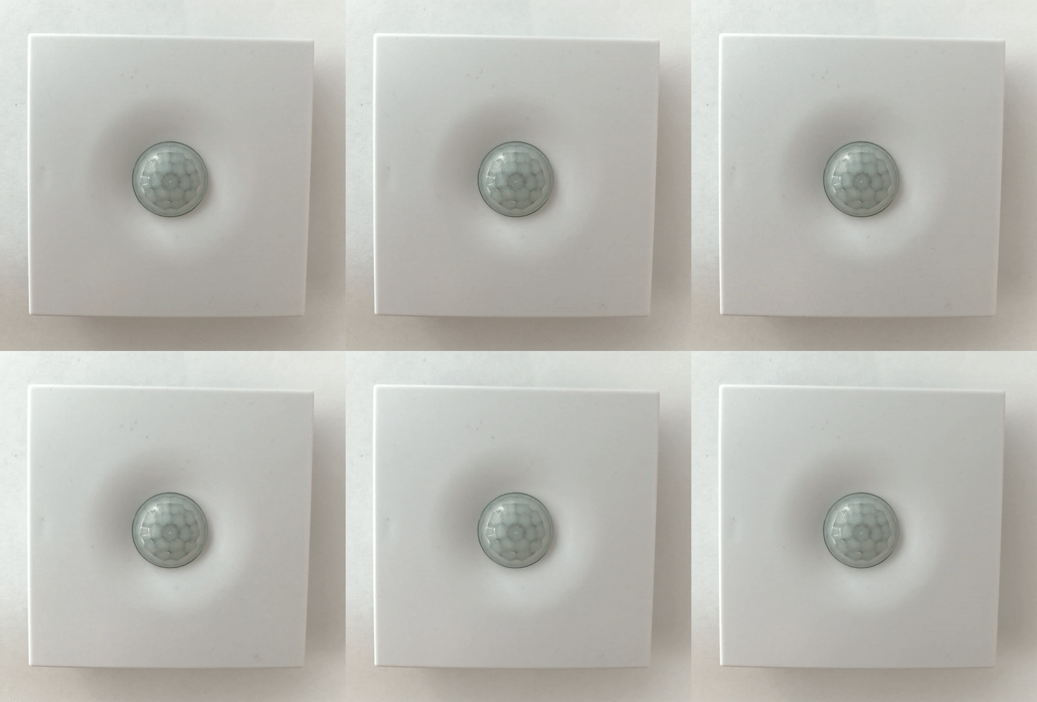
The receiver and eight infrared emitters are located behind the lens. Learn a remote-control command once, store it in a numbered cell, then replay it from Zigbee or Modbus. A command may contain up to 1,000 high/low pulse pairs whose durations are represented in microseconds. The transmitter is intentionally wide-angle and can control equipment visible from the sensor. For individual control of several nearby air conditioners, use dedicated directional IR transmitters.
Illuminance and sound
The illuminance channel uses an optical filter shaped to the sensitivity of the human eye and responds within about 1.5 seconds. The sound channel reports an A-weighted sound-pressure level in dBA and provides a configurable noise-detected state.
VOC and indoor-air quality
Units made before August 2023 can contain an SGPC3 VOC module. It takes about six minutes to become ready, returns 0xFFFF during warm-up and adjusts its baseline every 12 hours. Later units use an ENS160 VOC module and firmware 1.5 or later. It reports VOC and an air-quality index immediately, but its initial self-calibration takes about 24 hours. Keep the sensor powered continuously during calibration.
| AQI | VOC, ppb | Assessment | Recommended action |
|---|---|---|---|
| 1 | 0–65 | Excellent | Target condition; unlimited exposure |
| 2 | 65–220 | Good | Ventilation recommended |
| 3 | 220–660 | Acceptable | Ventilate and identify the source |
| 4 | 660–2,200 | Poor | Ventilate intensively and remove the source |
| 5 | 2,200–5,500 | Hazardous | Intensive ventilation; limit exposure to hours |
Carbon dioxide
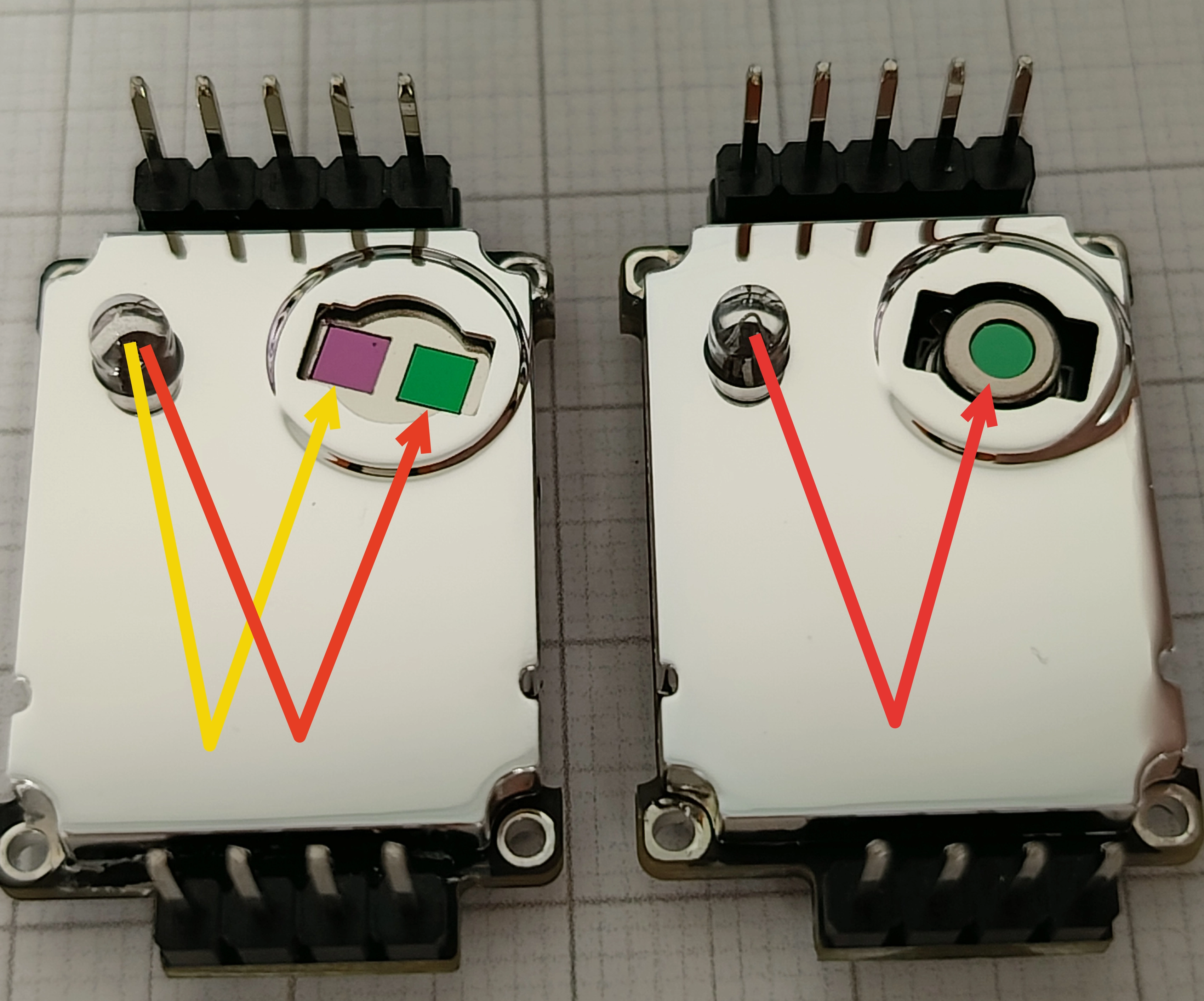
The optional CO₂ module uses the non-dispersive infrared (NDIR) principle.
Automatic baseline calibration treats the lowest reading observed over seven days as approximately 400 ppm. For reliable calibration, the room must be unoccupied or well ventilated for part of each week. If this cannot be guaranteed, calibrate the module manually in fresh air using the wired interface.
| CO₂ concentration | Typical interpretation |
|---|---|
| 400–450 ppm | Normal outdoor air |
| Below 600 ppm | Good indoor air |
| 600–1,000 ppm | Stale-air complaints may begin |
| 1,000–2,500 ppm | Drowsiness and reduced concentration are possible |
| 2,500–5,000 ppm | Adverse effects become more likely |
| 5,000 ppm | Common maximum eight-hour occupational exposure level |
Selecting Zigbee or RS-485 mode
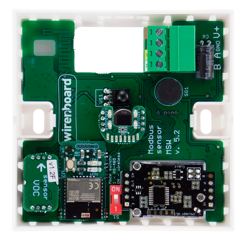
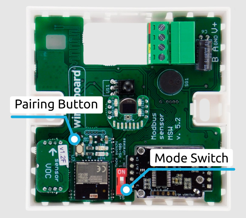
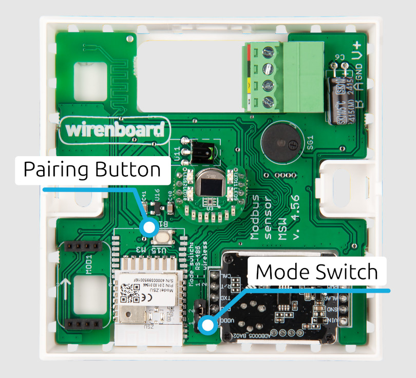
The factory setting is wireless Zigbee mode. Disconnect power and open the enclosure before changing the mode.
- Boards earlier than revision 4.56 use switch S1: ON is wireless mode and position 1 is RS-485 mode.
- Boards revision 4.56 and later use a jumper: position 2 is wireless mode and position 1 is RS-485 mode.
In wireless mode the sensor is a Zigbee end device and router. In RS-485 mode the radio may still join a coordinator as a router, but measurement data is not available over Zigbee. The radio communicates internally with the sensor controller at 9,600 bit/s. If controller serial settings were changed, restore the factory serial speed before switching modes.
Installation and wiring
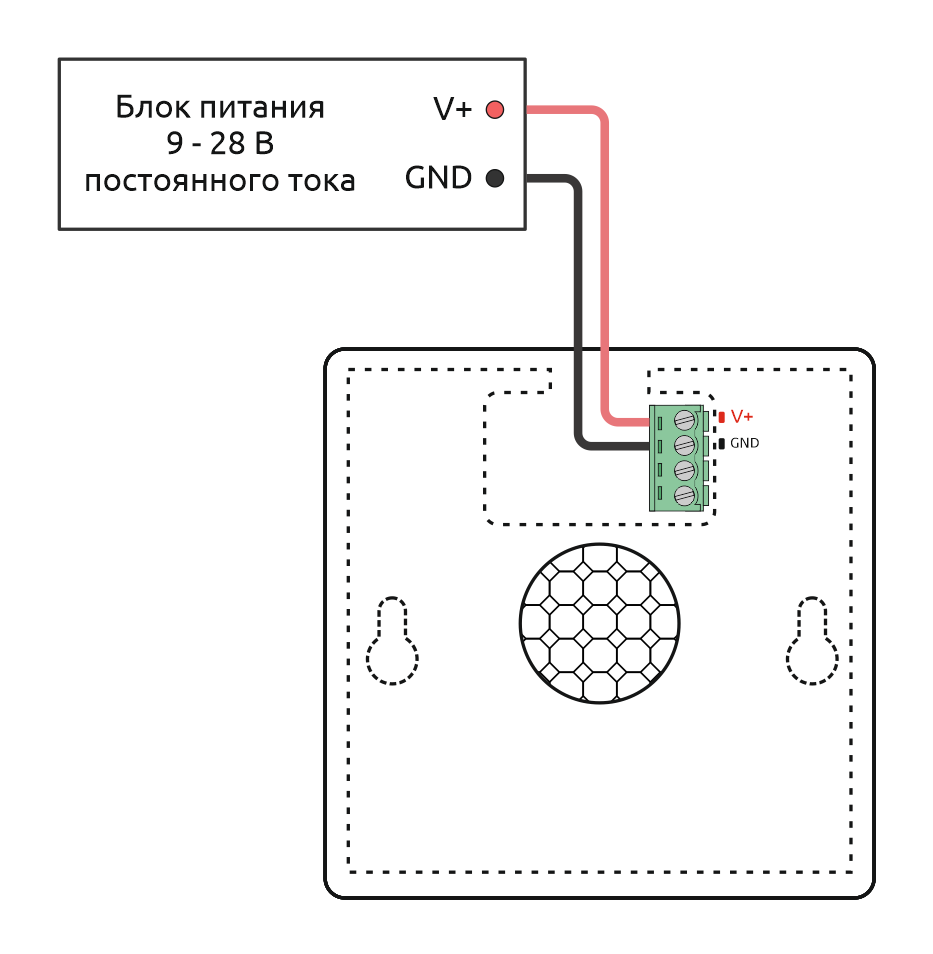
Connect 9–28 V DC to V+ and GND. The green status LED flashes during normal communication unless it has been disabled. Long cables require adequate conductor size to keep the voltage at the sensor within specification during CO₂ measurement and IR transmission.
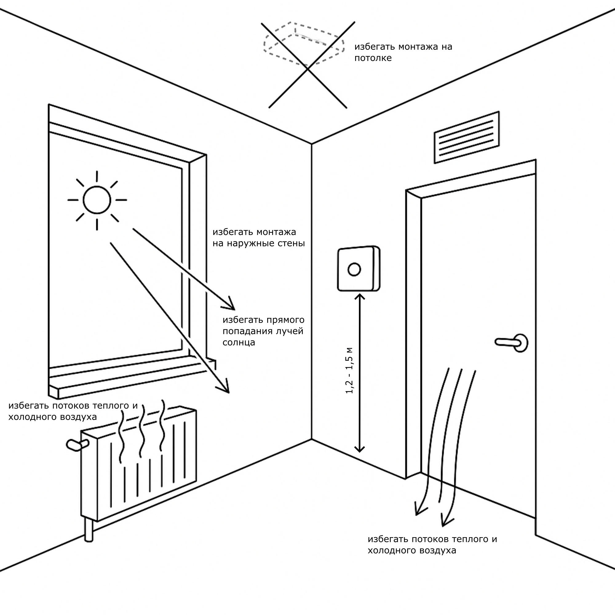
Mount the sensor on an interior wall, typically 1–1.6 m above the floor, away from sunlight, radiators, doors, drafts and local heat sources. Exterior walls can bias temperature readings. A 68 mm round European wall box can be used; the wall box is only for the cable and does not provide spare space behind the electronics. For surface mounting, use screws with heads approximately 7 mm in diameter and the 60 mm hole spacing.
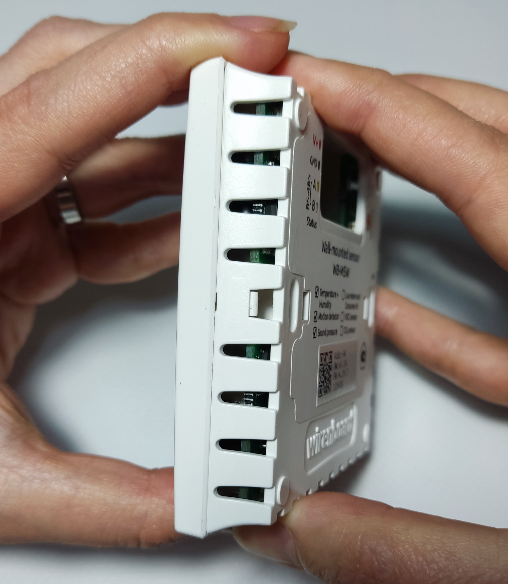
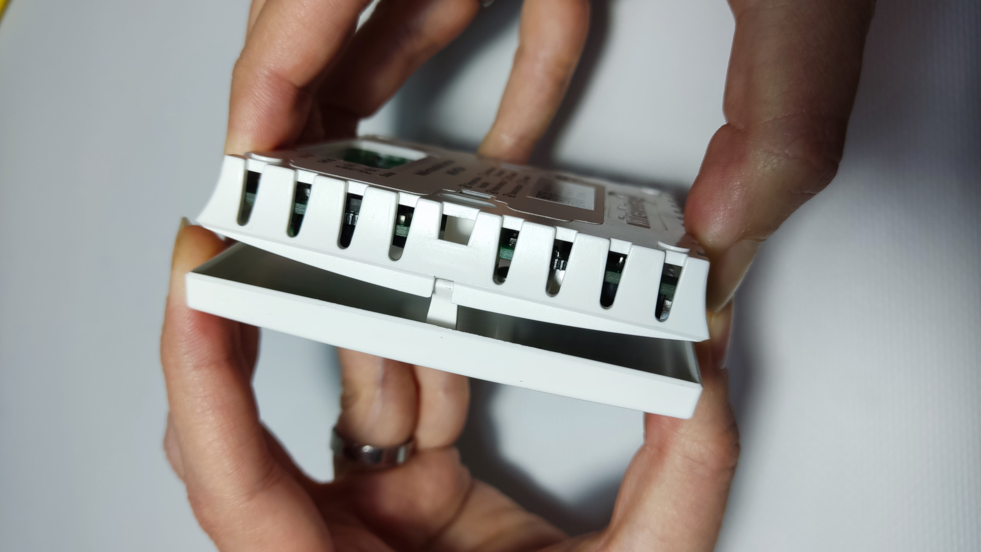
To open the enclosure, hold it with both hands, press the two halves gently and lift the front cover.
Pairing and removing the Zigbee device
- Enable pairing on the Zigbee coordinator.
- Open the enclosure and briefly press the Pairing button. The green status LED starts flashing.
- Wait for the device to appear in the controller, then disable coordinator pairing.
To remove the device from a network, first disable pairing on the coordinator, then briefly press the Pairing button. The green status LED stops flashing after the local network information has been cleared.
Controller integration
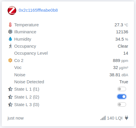
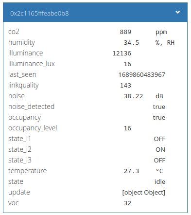
The sensor is supported by Wiren Board controllers with zigbee2mqtt 1.32.2 or later. A current integration exposes the following channels:
- temperature, temperature_offset, th_heater and humidity;
- co2, voc, illuminance and air-quality data where the corresponding sensors are fitted;
- occupancy, occupancy_level, occupancy_sensitivity and occupancy_timeout;
- noise, noise_detected, noise_detect_level and noise_timeout;
- state_l1 (red LED), state_l2 (green LED), state_l3 (buzzer) and activity_led_indicator;
- installed_version, latest_version and update state;
- linkquality, last_seen, uart_connection and uart_baud_rate.
MQTT control
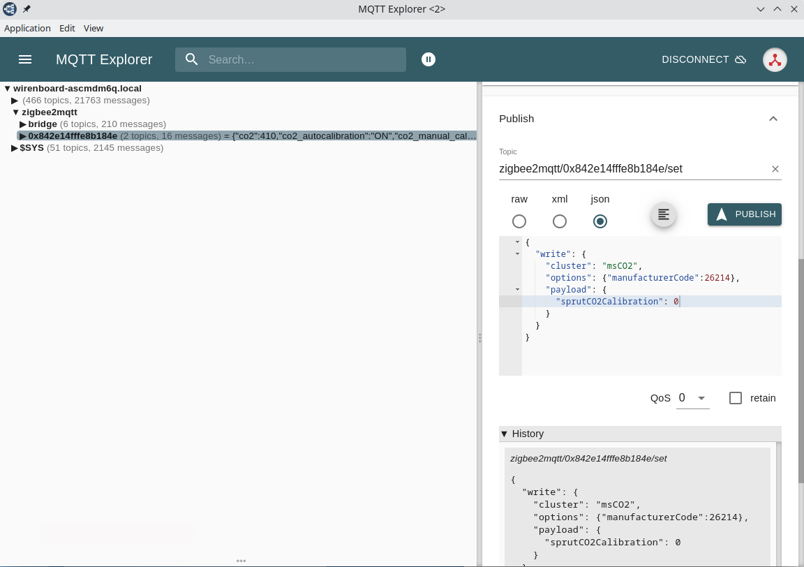
Publish commands to zigbee2mqtt/FRIENDLY_NAME/set. Replace FRIENDLY_NAME with the device name.
{"state_l1":"ON"}
{"state_l2":"ON"}
{"state_l3":"ON"}
{"activity_led_indicator":true}
Use OFF to turn an output off. Commands can be sent from MQTT Explorer or from a Wiren Board wb-rules automation.
Zigbee configuration and reporting
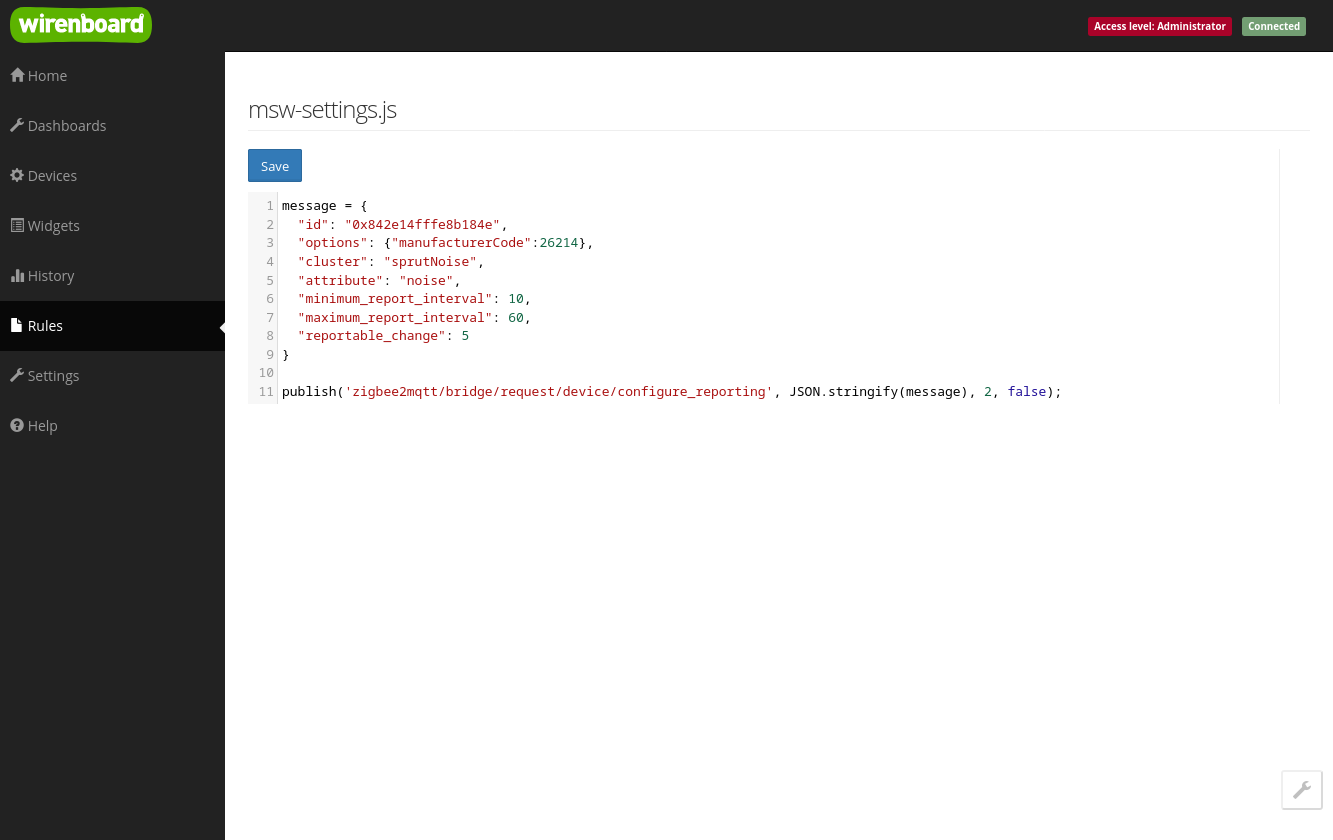
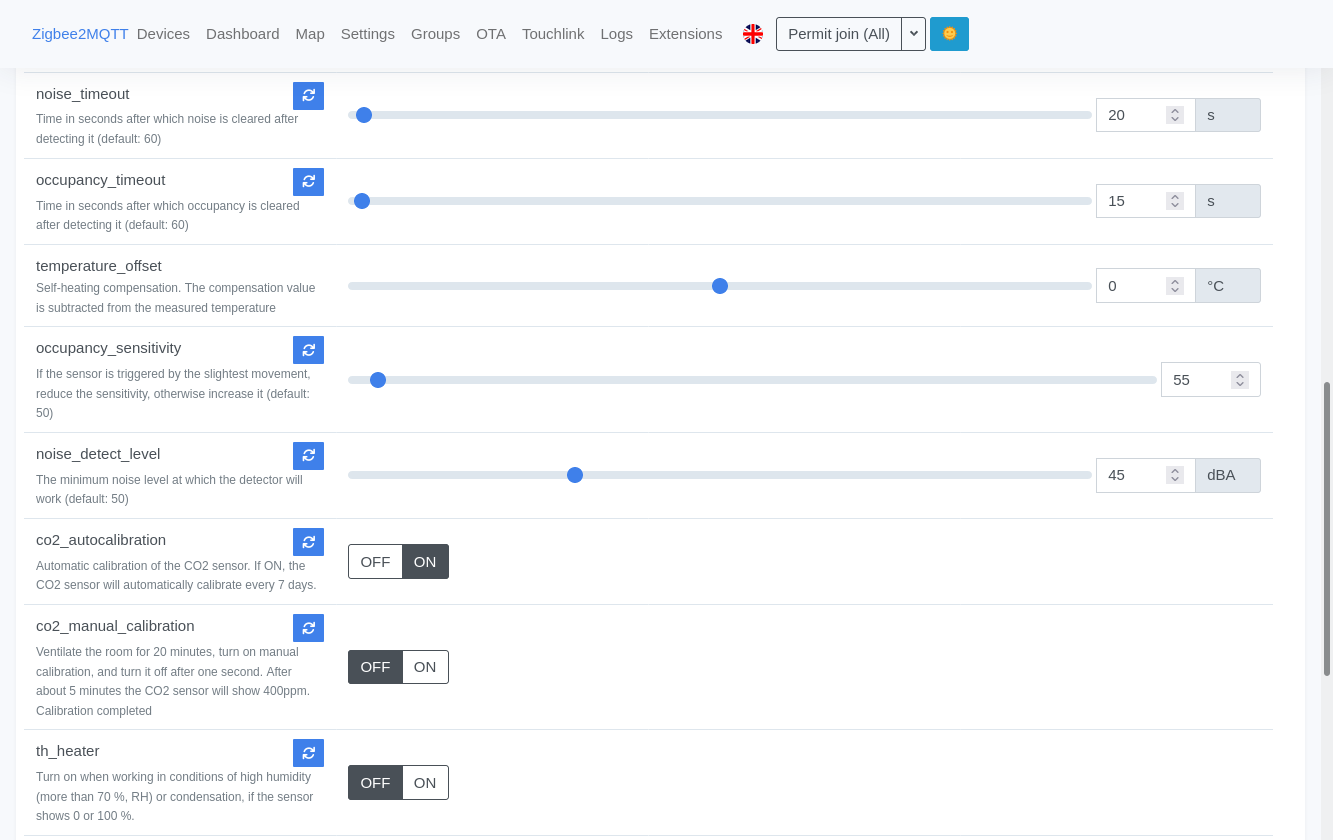
Parameters can be changed in the zigbee2mqtt interface or through MQTT. A reporting rule consists of a minimum interval, maximum interval and reportable change. Temperature and humidity changes are encoded in hundredths, so a value of 100 means 1 °C or 1% RH; other channels use their displayed unit.
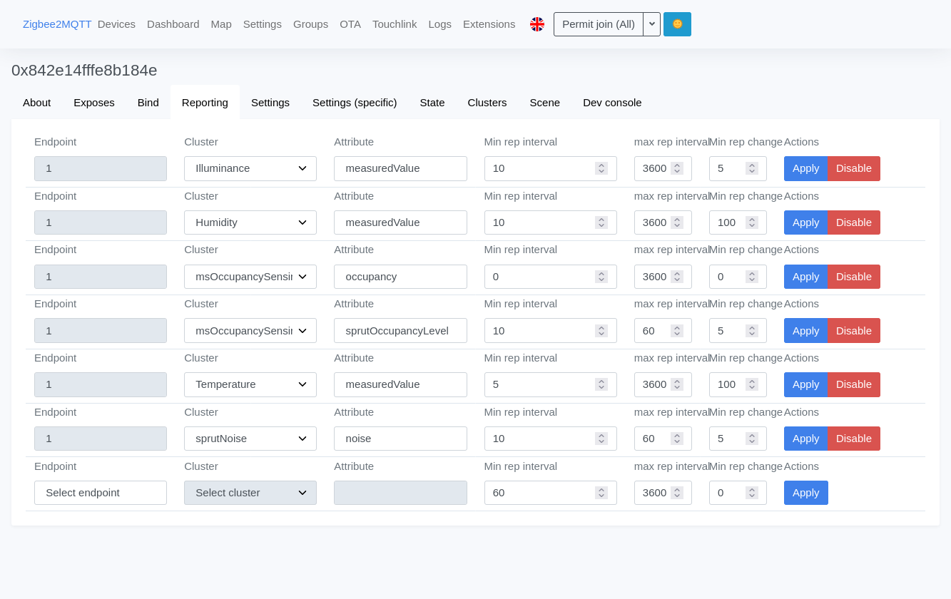
For direct MQTT configuration, publish to zigbee2mqtt/bridge/request/device/configure_reporting:
{
  "id": "FRIENDLY_NAME",
  "endpoint": 1,
  "cluster": "msTemperatureMeasurement",
  "attribute": "measuredValue",
  "minimum_report_interval": 10,
  "maximum_report_interval": 3600,
  "reportable_change": 100
}| Channel | Cluster | Attribute | Minimum, s | Maximum, s | Change |
|---|---|---|---|---|---|
| Temperature | msTemperatureMeasurement | measuredValue | 10 | 3600 | 100 |
| Illuminance | msIlluminanceMeasurement | measuredValue | 10 | 3600 | 5 |
| Humidity | msRelativeHumidity | measuredValue | 10 | 3600 | 100 |
| Occupancy | msOccupancySensing | occupancy | 10 | 60 | 0 |
| Occupancy level | msOccupancySensing | sprutOccupancyLevel | 10 | 60 | 20 |
| Noise | sprutNoise | noise | 10 | 60 | 5 |
| CO₂ | msCO2 | measuredValue | 10 | 3600 | 10 |
| VOC | sprutVoc | voc | 10 | 3600 | 10 |
For the manufacturer-specific occupancy-level and noise attributes, use manufacturer code 26214. Configurable parameters include:
| Parameter | Range | Default | Purpose |
|---|---|---|---|
| noise_timeout | 0–2000 s | 60 s | Time the noise-detected state remains active |
| occupancy_timeout | 0–2000 s | 60 s | Time the occupancy state remains active |
| noise_detect_level | 0–150 | 50 | Noise trigger threshold |
| occupancy_sensitivity | 0–2000 | 50 | Motion sensitivity |
| temperature_offset | −10 to +10 °C | 0 °C | User temperature correction |
Infrared command storage
The 80 persistent memory cells are numbered 0–79. Use the following commands on the device set topic:
{"learn_start":0}
{"learn_stop":0}
{"play_store":0}
{"clear_store":0}
Replace 0 with the required cell number. For temporary RAM learning and playback use:
{"learn_ram_start":"ON"}
{"learn_ram_stop":"ON"}
{"play_ram":"ON"}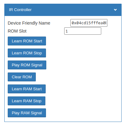
Fail-safe action
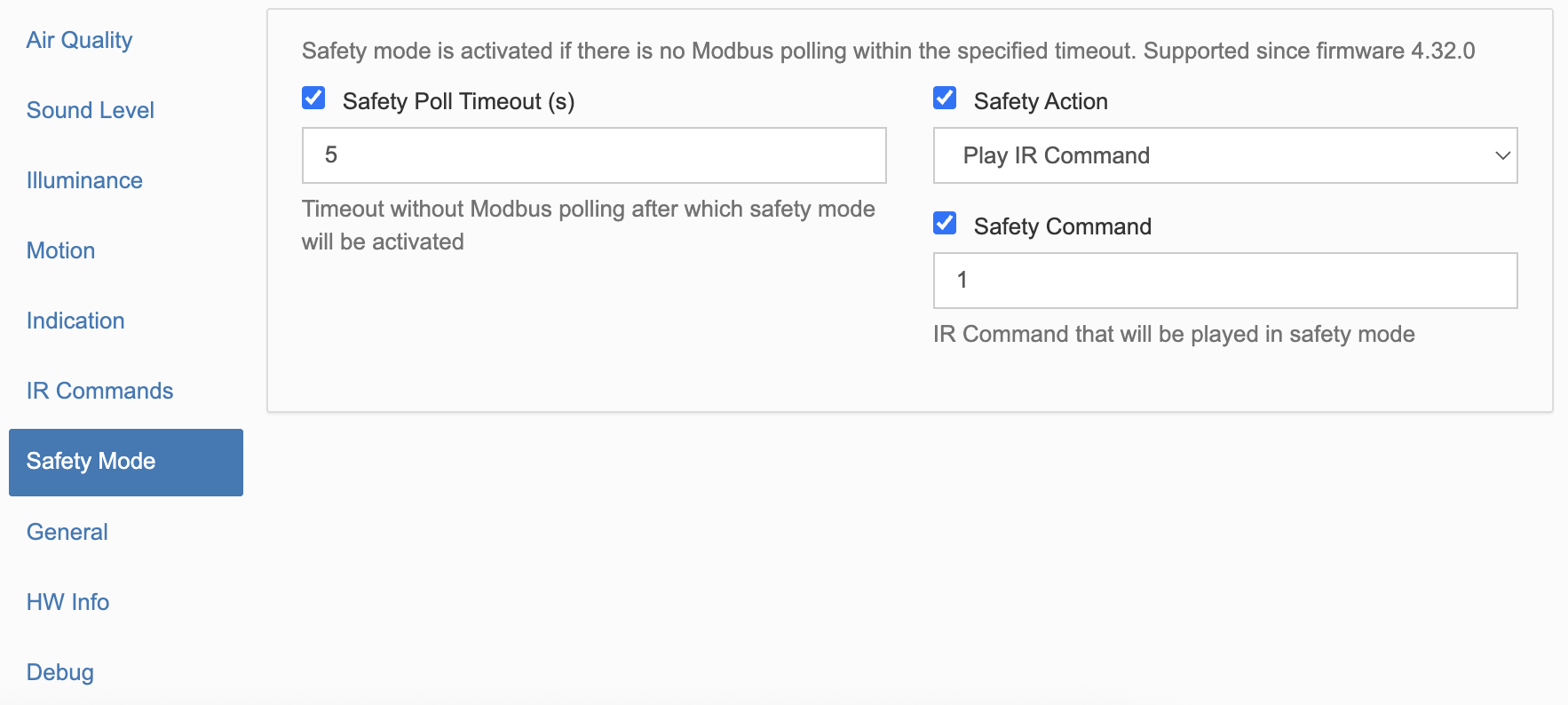
A fail-safe action can replay one stored IR command if controller communication is lost. The timer restarts after every successfully processed Modbus packet; the default timeout is 10 seconds. Normal operation resumes automatically when communication returns. By default, no IR command is assigned. Configure the timeout, playback action and stored command number before enabling this function.
Firmware updates
The product contains a main sensor/Modbus controller and a Zigbee radio controller. A Zigbee over-the-air (OTA) update can update both controllers. An RS-485 firmware update updates only the main controller.
For reliable OTA updates, add the following settings to the zigbee2mqtt configuration and restart zigbee2mqtt:
ota:
  image_block_response_delay: 50
  default_maximum_data_size: 60
systemctl restart zigbee2mqttOpen the device page, select the firmware update control and start the update. It may take about 30 minutes. Do not remove power. If an update fails or power is interrupted, remove the device from Zigbee and pair it again before retrying.
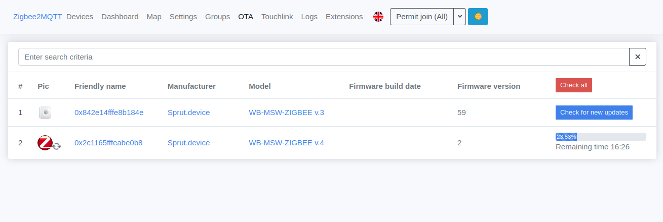
zigbee2mqtt 2.8 and later can display the main controller version and signature in its developer console under the sprutDeviceBase cluster: deviceVersion, deviceSignature, deviceBootVersion, componentVersion and componentSignature.
One-time migration to official firmware
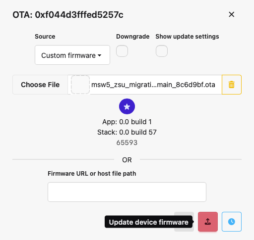
The official wireless firmware line introduced in August 2026 requires zigbee2mqtt 2.13.0 or later and devices with serial number 196189 or higher, manufactured from April 2024. Download the transition firmware supplied for this hardware, then on the device page choose Firmware version → Source → Custom firmware, select the file and start the update. Allow up to 30 minutes without disconnecting power. This migration is performed once. After migration, the Zigbee model is reported as WB-MSW-ZIGBEE v.4; the earlier partner branch reports WB-MSW4.
Dimensions and internal layout